Jump to content


cheerios

Member Since 05 Jan 2009
Offline Last Active Jul 30 2021 01:44 PM

Topics I've Started

China Darts Review

11 January 2016 - 06:53 PM

So my order of China darts came in today so I had to test them out.


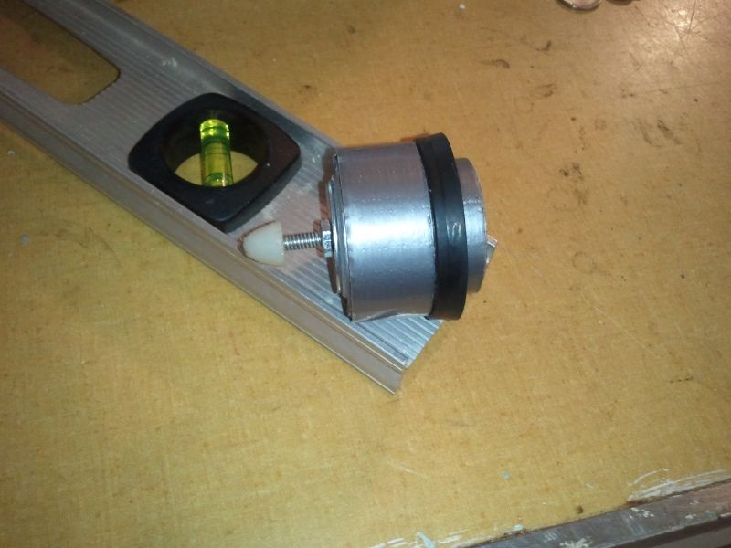
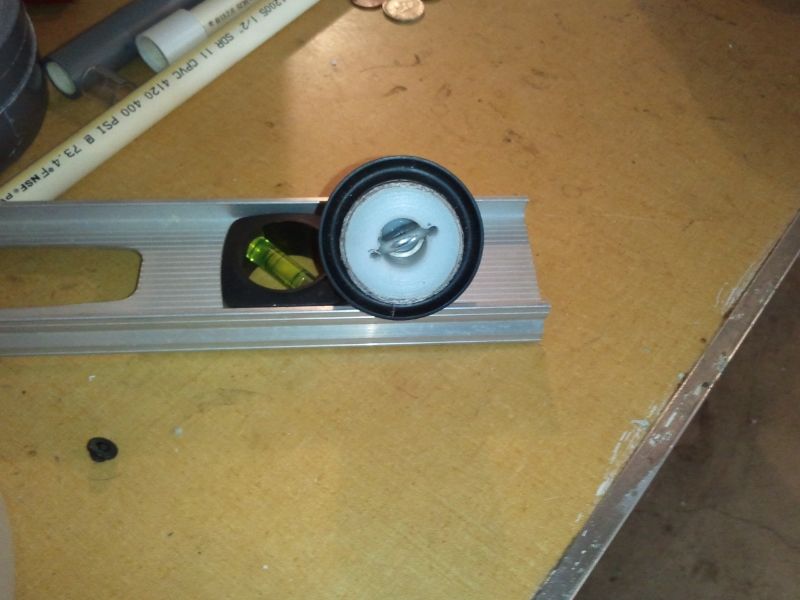
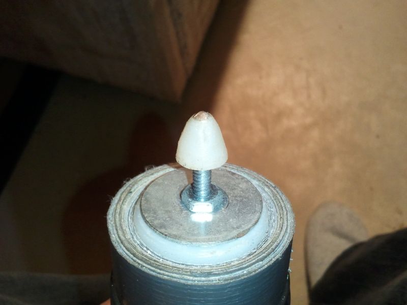
First thing I did was cut them down to 35mm in length so that they were similar in length to my MHA silicone dome darts. These darts have a bigger dart tip comparable to those that Xplorer produce, and the foam they are made out of is denser than that of NERF elite darts. These darts do weigh a noticeable amount more than MHA darts just by feel, but I don't have a scale cause I'm not a drug lord and I don't have any use for a scale that weighs .00 grams.


7e295725-ed0e-4050-910e-5893597424af_zps


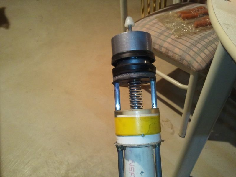
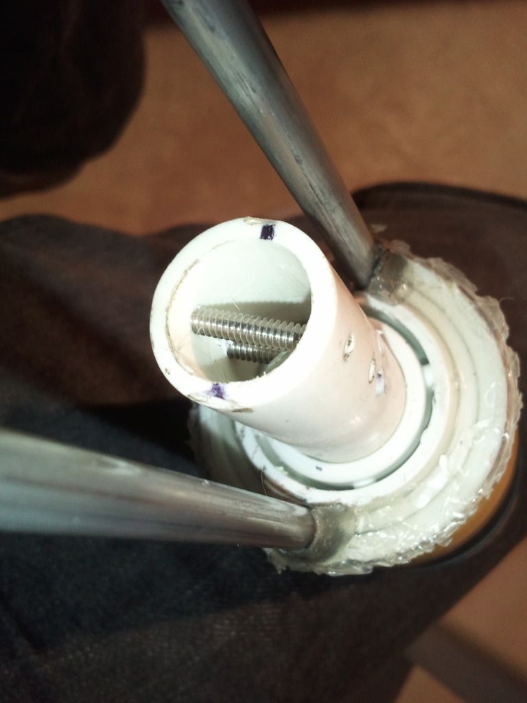
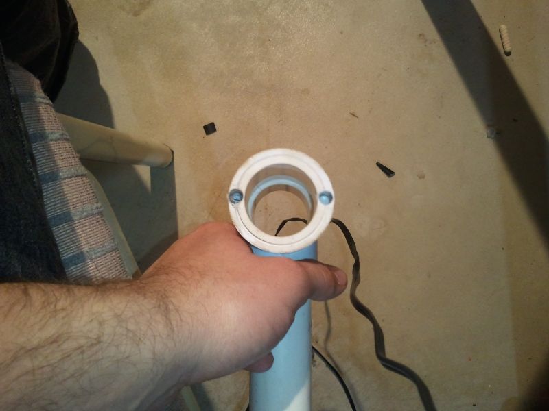
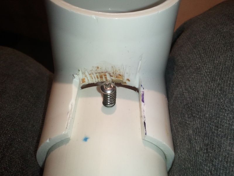
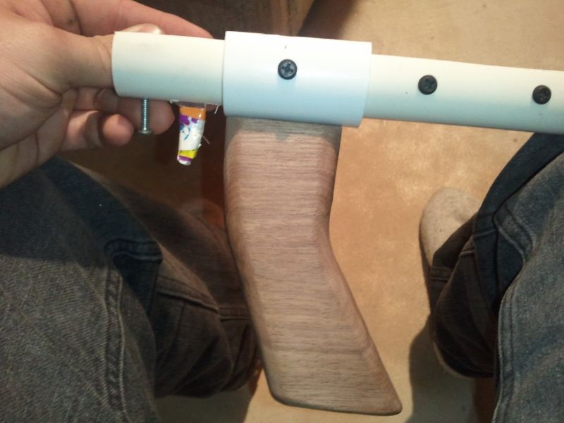
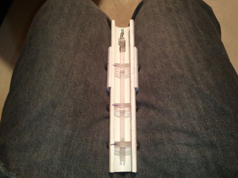
Then I tested them in an overhauled SM1500, Zorn's FAL2, and then a Plusbow. The FAL2 was fitted with the same hopper setup I've been using with MHA darts since 2013 so as to eliminate that as a variable for their hopper-ability. The Plusbow was fitted with an unmodified 1/2" PVC Wye hopper and a 12" CPVC barrel.


749e6f51-dc96-4287-8455-a0ac09e04a03_zps


Both the FAL2 and Plusbow were fired 100 times and their record of fires to misfires were recorded, and the results are as follows:

China Darts

FAL2: 97/100

+Bow: 100/100


MHA Darts (Minor Cornstarch)

FAL2: 92/100

+Bow: 92/100


#6 Slugs

FAL2: 99/100

+bow: 100/100


The accuracy of these darts is superb; even out of a ridiculously overpowered overhauled SM1500 the darts didn't spin out and shot laser straight. The same can be said about the FAL2 and Plusbow.


As for range variance between these, MHA silicone domes, and Slugs... I didn't test it cause It's too cold and it honestly doesn't matter, but I would take an educated guess and say that these will out range MHA domes and slugs when fired out of the same blaster.


Pros:

  • They seem to feed more reliably than MHA darts, but more testing needs to be done before this can be confirmed.
  • Significantly more aerodynamic than slugs
  • $0.05 per dart
  • METAL FREE

Cons

  • They're made with black foam which will make recovery a bit of an issue.
  • They're more aerodynamic tip could inflict more pain compared to Slugs or MHA domes.
  • You have to cut them down to make them hopper.

The BullShit

09 February 2014 - 01:08 AM

This isn't really a write-up, but it's detailed enough that I feel someone with a little bit of effort could build one based off these pictures and descriptions.

The BullShit was built mainly as a proof of concept blaster. This was never intended to be a working prototype, but it worked well enough the first build that I feel comfortable
enough posting my results. I wanted to make something that was bullpup, but didn't require the barrel to come be seated on top of the blaster, or require tubes with slots inside
more tubes with slots.

2014-02-08233732_zpsd0a38087.jpg
2014-02-08233924_zps49e1f9fe.jpg


Front Bushing

It started with a spare part that I got from Ryan and Kane back in June. It's a 1.5" x 1/2" PVC bushing with 1/2" pvc going through both sides 1", then the rear side was inserted in 2" PVC and had
resin poured in around the 1/2" PVC to create a snug fitting 2" internal bushing. The resin was later sanded down to 3/8" tall making the bushing a total length of 1.4375".

97137cde-a475-4484-85c5-a9b4ae6a64c8_zps

Barrel Shroud/ Pump Guide

The next part made was the barrel shroud/ pump guide tube. It's made of 1" thinwall PVC 12" long with a slot cut 1" from one end 1" wide and 3" long. The slot is just barely big enough to allow
the wye to fit in the tube and completely on the 1/2" PVC with enough room for a screw to be put through the wye and PVC.

Unfortunately due to poor lighting and excess flash the original picture was super shitty. I edited it enough to see some detail about what I'm talking about.

674a2329-26ba-4921-8594-aee90b2c4113_zps

Plunger Head & Rod

The plunger head is made of 1.375" x 5/8" UHMW Tube and 1.375" x 2" U-Cup seal. The Plunger head is 1.5" long, with .875" of duct taped wrapped around the back to match the diameter of the u-cup base.
and .25" in front of the seal just enough to keep the seal from coming off as you prime it back.

2013-07-31112358_zps513b16bb.jpg

The plunger "rod" is just an eye bolt nested inside the UHMW tube with a lathed piece of .5" nlyon for the ramp on the back of the eyebolt. To keep the eye bolt in the plunger head
I had to reduce the I.D. down to 1/8"; to do that I nested a .5" of .625" x .5" tube inside the plunger head. Then I nested a .5" x .125" nylon spacer in that.

You have to tap both spacers, and the rear catch spacer also need a set screw in the side to keep it on the rod. To keep all of the nested tubes inside the plunger head you will need a fender washer on the back kept on with a nut.

Front of the plunger head
f1d7b51b-64a5-4fa9-8e17-a8121e9c8c21_zps

Back of the plunger head
2014-02-01162635_zps91d33df5.jpg

Priming Plate

This part's purpose is to push back the plunger head and seal against the front bushing to reduce air loss. I made mine out of PVC, but a wide variety of materials could be used as well.
I would highly recommend aluminum if you have access to a lathe. With the plastics, the plate can be turned down on a drill press with a metal lathe cutting tool mounted to the table.

It's 2" wide with a .25" thick chunk turned down to 1.375" for a second u-cup to seal against the plunger tube. The middle hole is drilled out to .75" to allow proper clearance for the spring.
It also has 2 .25" holes for the aluminum rods to sit in. There are no real dimensions for the spacing or placement. The rods are held in place with a set screw on each side.

Both sides have a 1.875" x .75" rubber washer glued on to act as padding and to help seal against the front bushing.

2014-02-01162427_zps0eba3e4a.jpg

2014-02-01162225_zpsbd5006df.jpg

Priming Rods

The rods are 2 .25" aluminum rods cut to 9.5" long. They have holes drilled in the sides on both ends to attach to the priming handle and priming plate.

The rods should be placed as close to the 1" thinwall PVC as possible without touching to give more material on the edge of the priming plate for set screws to drill in.

The extra holes and screws in the PVC are what I'd like to call fuck up holes. Just ignore them.
2014-02-01162827_zpsf21ff75b.jpg

Priming Handle
The priming handle is just a 1.25" tee with 1.25" PVC inside. It has holes drilled in it for the aluminum rods to slide in (.5" deep minimum any less and it cracks).

2014-02-01164127_zpsaa73d675.jpg

Main body, Stock, and Catch

Main body is 7.75" long of 2" PVC.
The Catch is a standard 2" Rainbow catch.
The stock is a 2" PVC tee with a 1.25" x 1" slot cut out to allow clearance for the handle & trigger assembly.

2014-02-01163312_zpsbbf8fbb0.jpg

Handle and Trigger

The handle is a walnut Rainbow handle attached to 1" PVC using half of a coupler.
The trigger assembly is a LouieC3 "Revshot" trigger shortened to 6" trigger and 7.875" 1" PVC cover.
For the trigger spring I just used a spare stock nerf gun extension spring.

2014-02-01163619_zps6e699fa1.jpg

2014-02-01163539_zps2d160d4f.jpg


Additional notes
The spring gets attached to the eyebolt and the screw running through the wye and .5" PVC. If you use Sch. 40 PVC you'll have to ream out the PVC for the spring to fit freely.
In the future I'll use an aluminum priming plate.
The next one (if there is a next one) will have a 3d printed bushing with spaces for o-rings so I don't have to use hot glue for sealing the front.
I'll use 1.25" PVC couplers for the priming handle in the next one or replace the current one.
It is able to fire out of a 10 dart hopper with no feeding problems. 3.5" of draw is plenty, no need for 7" draw blasters.

And Ranges, it is way too cold and snowy to actually measure. But in the fall it was shooting high 80's to low 90's with a 4.5" CPVC to 5" sch 80 barrel and silicone domes.


Directory of Homemade Nerf Gun Build Guides

02 November 2013 - 09:29 PM

Carbon has been pretty busy lately so I'm taking over the Directory for him. Please don't post in the thread. Here's the original directory thread by Carbon for posterity.

The Nerfhaven Homemade Directory is the repository of past completed projects of the Haven. Use it as a resource to see whats been accomplished before, to find new (or old) techniques, or to get inspiration for your next project. PM me if your homemade isn't in the directory or if certain links aren't working. PM Aeromech if your writeup doesn't appear here within a week of posting.

This post will be updated as new projects are added to the forum.

Helpful Threads for Building Homemade Blasters
Read the first three threads before building your first homemade.
General Reference Thread
So You Want To Build A Homemade?
Guide to Machining Plastics by Captain Slug
Guide to Solvent Welding Plastics

Just click the "show" button near the spoiler bar to see that version of the directory.


Administration Picks

Spoiler


Write-Ups


Sorted by Priming Styles
Spoiler


Pump action U Channel blaster

29 July 2011 - 05:59 PM

I first got the idea for this blaster while looking at a picture of Split's LAB. I thought about how he used the aluminum U channels to hold together his blaster and I realized that they they could be used to make a pump action blaster. So before we go on to the blaster I would like to put recognition for a few things, Stark for his Rainbow catch, Ryan201821 for his rainbowpump templates.

Tools
Scroll saw or band saw
Power drill or drill press
Screw driver
Drill bits (specified in the writeup)
6-32 tap

Materials
PVC U channel 85065K33
3/8" square PVC bar 8660K31
1/2" Square PVC bar 8660K33
1/2" thick 6" x 6" PVC sheet 8747K635
1/4" polycarbonate sheet 12" x 12" 8574K11
3/8" 6-32 screw 90402A146
3/4" 6-32 screw 90272A151
Catch spring 9657K39
Spring I used 9637K25

Body and Catch

Lets begin. Print out the templates from here: [url="http://ryan201821.ne...mptemplates.doc"]http://ryan201821.ne...mptemplates.doc

Then place them on the materials. Set the piece with catch templates aside for now.
Posted Image

Cut out everything but the catch pieces. Sand the handle, the trigger, and the side plates of the handle unless you want to diddle your hand.Don't forget to drill the holes on the top of the handle.
Posted Image

Assemble your handle, mark where the holes are on the top of your blaster.
Posted Image

Drill the holes out with a bit big enough to fit your screwdriver of choice.
Posted Image

Now get your 5/32 bit and drill through the big holes, and out the other side so the handle can be attached.
Posted Image

Now get you catch piece templates, we have to modify them to work with our 1/2" PVC bar. Make the circles in the center of the catch into squares. Cut it out and drill the needed holes.
Posted Image

Assemble your catch and and test fit it in your plunger tube, if it doesn't fit sand it down. This next part is hard to explain. You need to line up the middle of the catch with your trigger then make a mark where the screw and spring should go into the middle catch piece.
Posted Image

Take out the catch and remove the handle. Drill a 5/32 hole for the screw that holds the spring on into the plunger tube. Use a 3/4" 6-32 screw for this.
Posted Image

The spring rest needs to be screwed into the plunger tube, Use 3/8" 6-32 screws. There aren't really any good directions for this. (Look at the picture)
Posted Image

You can now fully attach the handle, this what you should have now.
Posted Image

U channels

Cut 2 27" sections. Measure from the front of the U channel 2 1/2" then again 3 1/4". The mark at 2 1/2" is where the front of your plunger tube will sit, and the mark at 3 1/4" is where you will drill with a 7/64 drill bit into the bushing. Tap the hole then screw in a 3/8" screw.
Posted Image

Drill and tap another hole 10 1/2" back screw that in with another 3/8" screw.
Posted Image

Do this to the second U channel as well.
Posted Image

Plunger Rod

Unscrew the bushing and cut a 12 1/4" section of 1/2" PVC rod. Then cut a catch notch 4" back and make a mark 1 1/2" back then another 6" back from that mark. Drill those marks out with 1/4" drill bit then connect the holes with your scroll saw.
Posted Image

Attach your seal and cut 9" of the spring of your choice.

U channel part 2

Finish taking off your U-Channels. Then measure back 14 1/2" and measure back from there 5 1/2". Drill the marks out with a 1/4" drill bit. You can then play connect the dots with your scroll saw, to make the slots.
Posted Image

Do this for both of the U-channels. When your done you can mount these back on the body of the gun. Install the plunger rod and bushing as well. (Don't forget to lube the seal)

Priming Rod and pump handle

Now your in the home stretch. Cut 2 15" sections of 3/8" PVC rod. (Notice they nest nicely in the U-channels) Drill a 11/64 hole a half inch away from on of the ends. Screw in a 3" 8-32 screw, you need it to go through the priming bar then the plunger rod and then the other priming rod.
Posted Image

The pump grip is a made out of 1/2" PVC sheet and 1/4" polycarb. cut out 2 2"x3" rectangles out of polycarb and a 2 3/4" x 3" square out of the pvc sheet.
Posted Image

Assemble it like this:
Posted Image
A couple screws on each side is sufficient

Once that is done connect it to the priming rods by screwing it in.
Posted Image

Your blaster is now done minus a stock. I made mine out of 1/2" pvc sheet, I cut out a 1 1/2" x 6" rectangle and screwed it in. But you can do it an way you want.
Posted Image
Final thoughts

This is still a "Prototype" blaster, I have already made a list of things that I need to fix.

The U channels are flimsy because of the giant slots in them, so in Rev.2 I'll fix that by making a reinforcement to the bottom and top of the U channels with a polycarb sheet.

I chose to use a [k25] spring which was not the best choice, I'm having issues with it catching in the catch notch and it causes to much friction on the priming rod, I'll be looking for a spring with same power but a bigger I.D.

I tried to not use any aluminum on the blaster which I successfully did, the blaster doesn't sound like death like Ryan's Pumpbow which had metal on metal to prime the blaster. But I think that that might not have been the best idea on my part, the blaster in now less sturdy because of this choice.

Also, sorry for the bad pictures; I got a new camera and I still need to learn how to use it.