- NerfHaven
- → popatachi's Content
popatachi's Content
There have been 158 items by popatachi (Search limited from 10-February 97)
#263999 At3k Pump Fix And Modification
Posted by popatachi on 31 January 2010 - 10:08 PM in Modifications
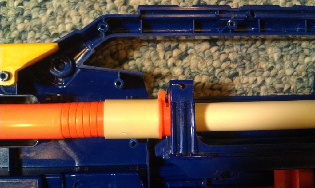
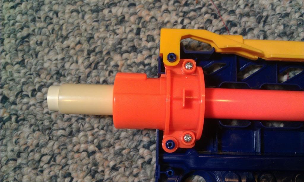
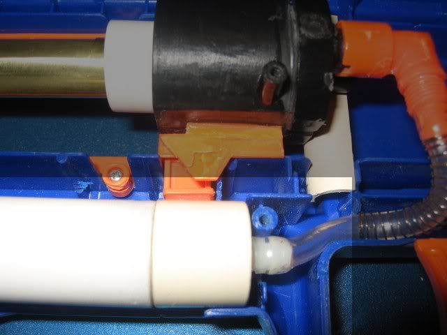
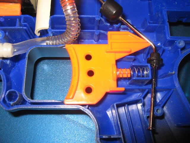
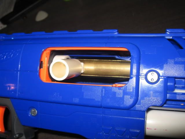
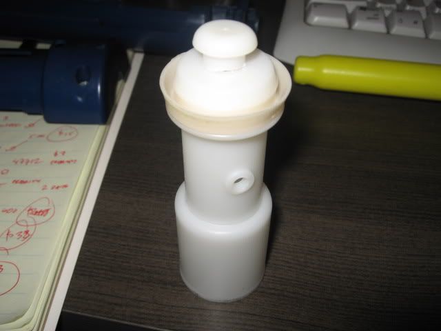
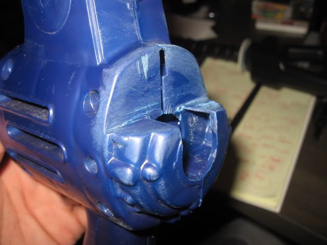
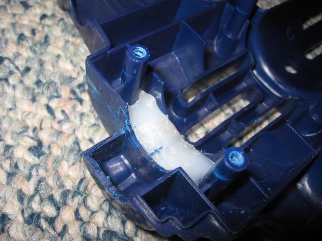
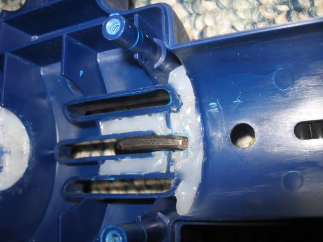
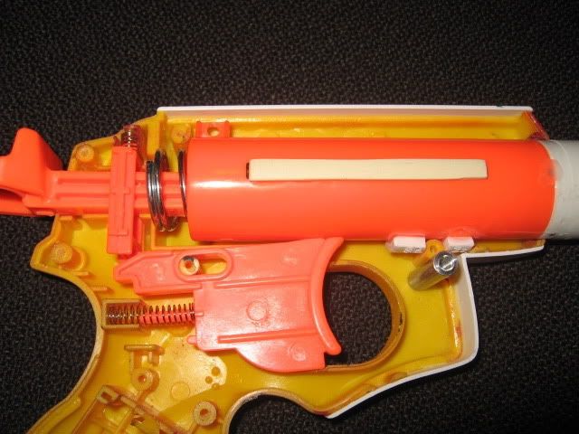
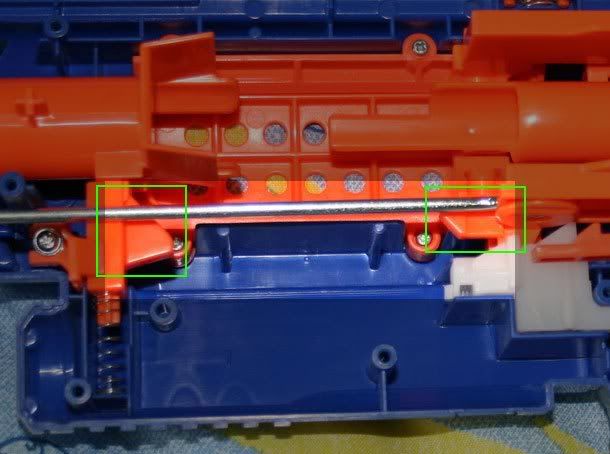
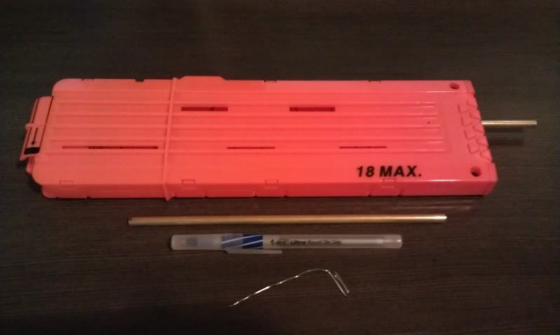
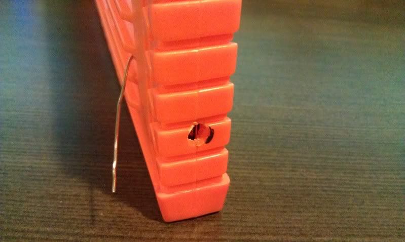
I carefully cut out the back of the pump wall and was able to determine how the check valve works. Here is the basic breakdown of the valve. This can be assembled again with styrene and glue.
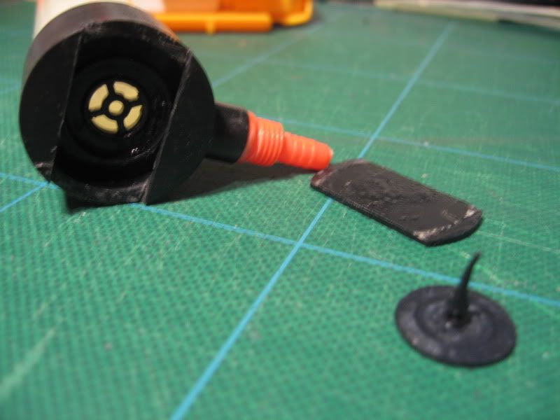
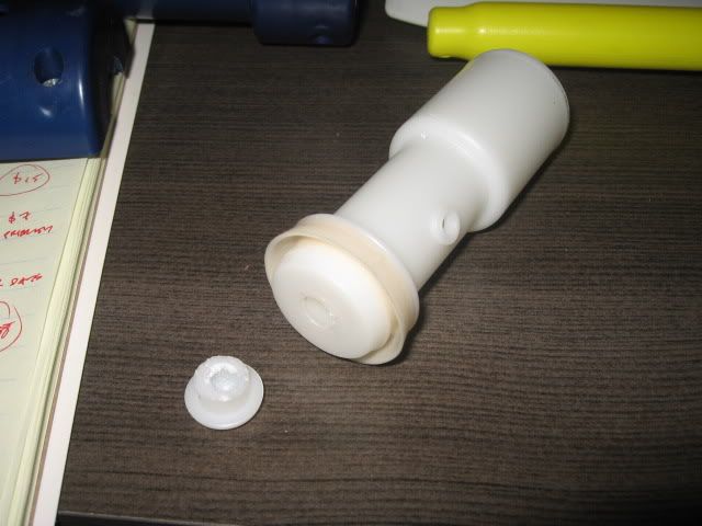
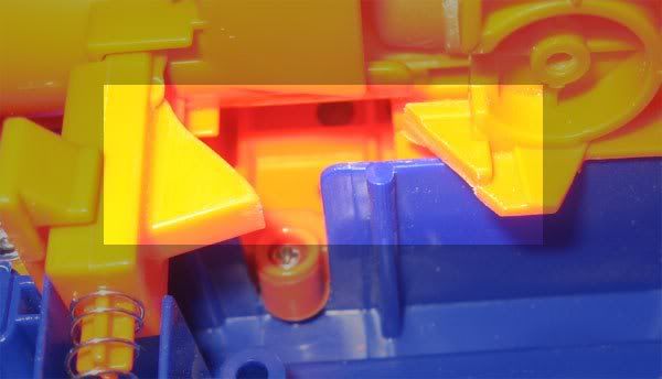
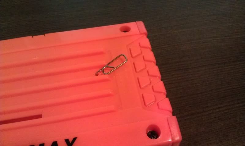
The check valve which is made of rubber is blue.
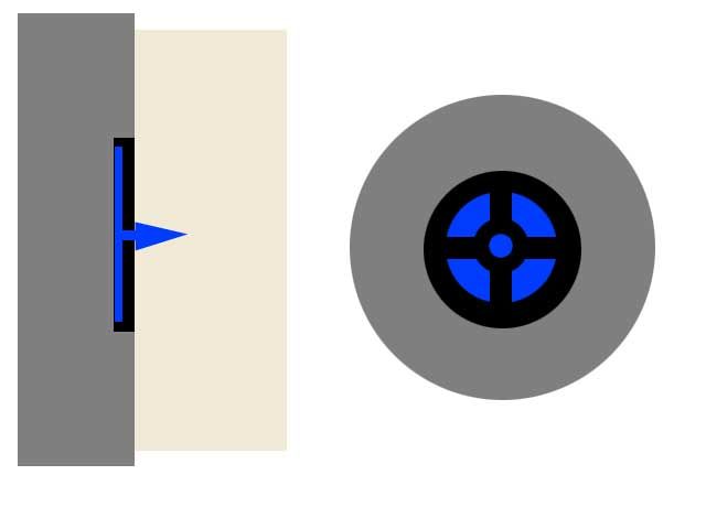
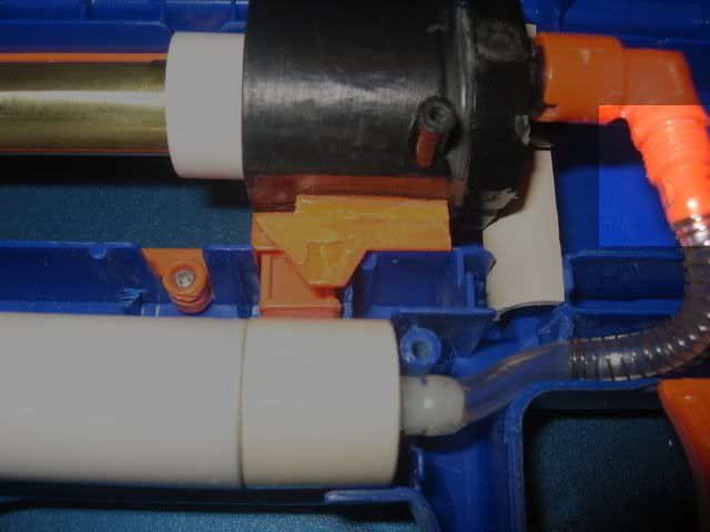
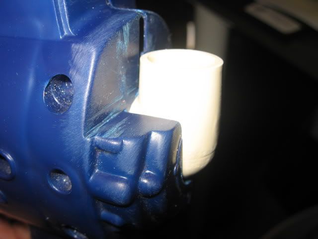
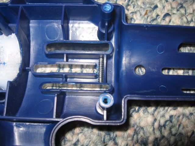
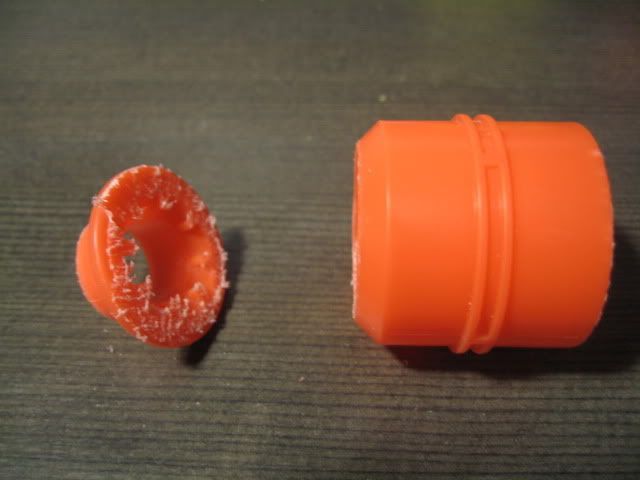
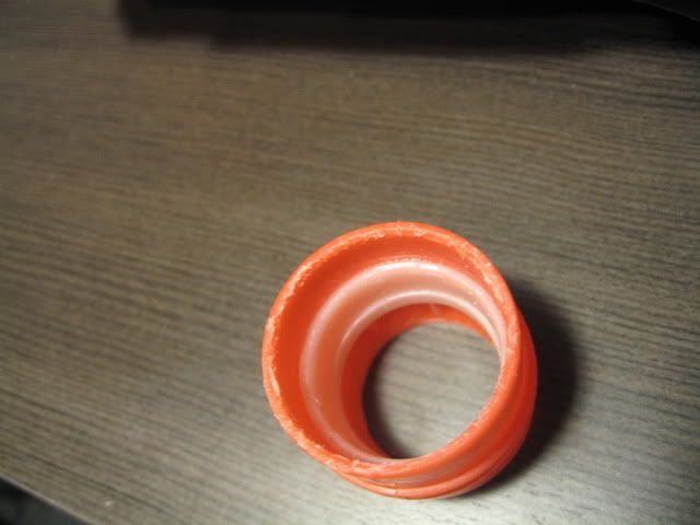
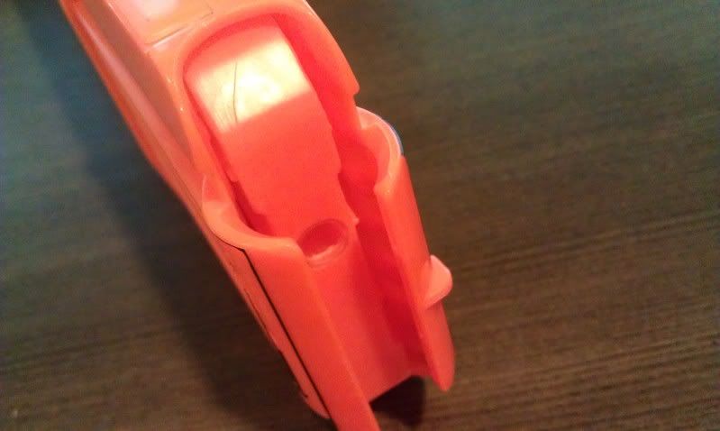
The valve stop is inside the pump tube and if that is dislodged (gets pushed into the back of the chamber), the check valve will fail. It was dislodged for me when I used a homemade pump. The stock pump head has a small hole in the middle of the head for the OPRV but also so the pump head does put too much pressure on the check stop to dislodge it.
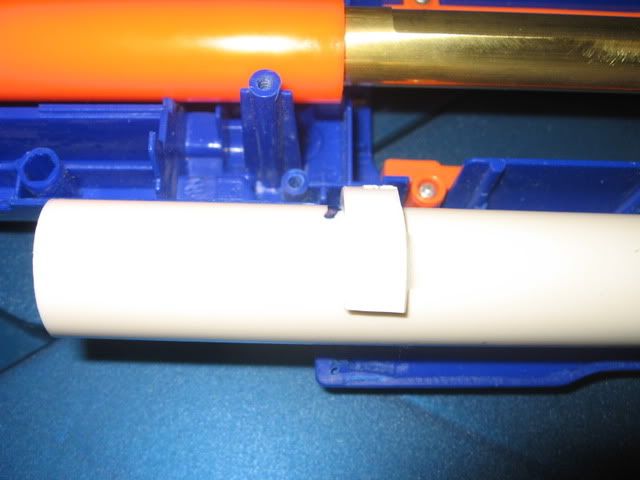
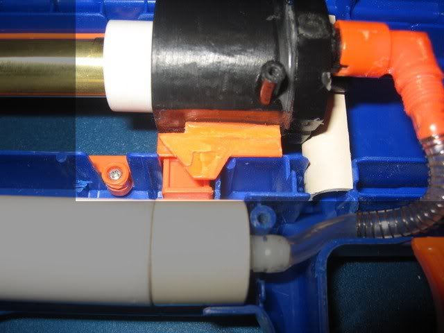
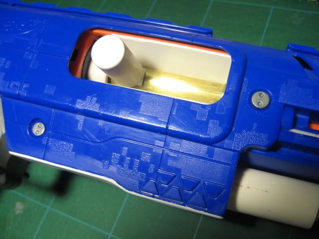
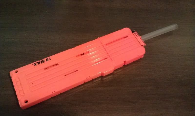
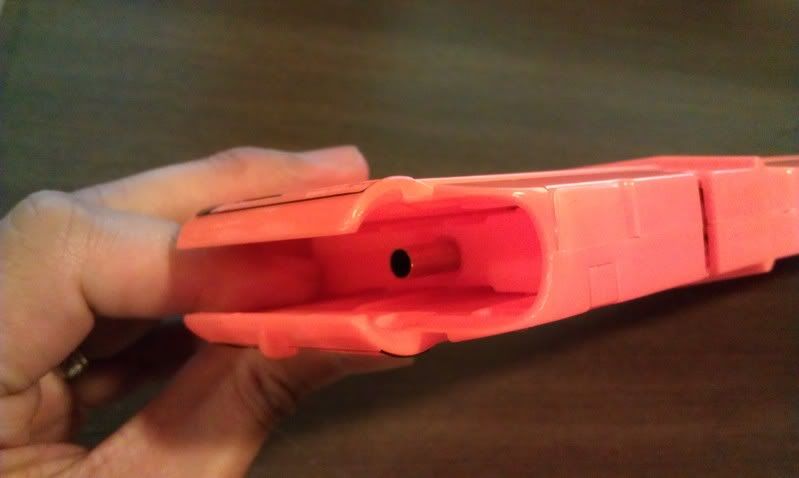
By using a plugged pump or a homemade pump where the pump head is flat, it can cause the valve stop to be pushed back and dislodge. In my next pump head, I simply coned out the head enough to avoid the check stop. When plugging pumps, be careful that it won't dislodge a check valve that might be in the pump tube.
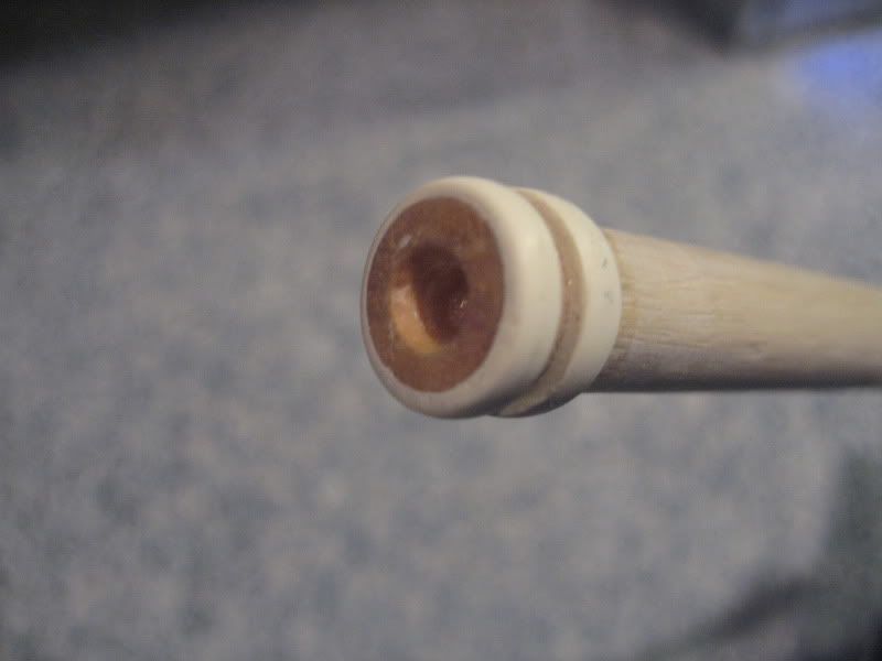
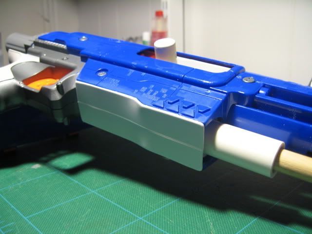
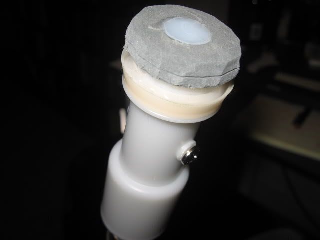
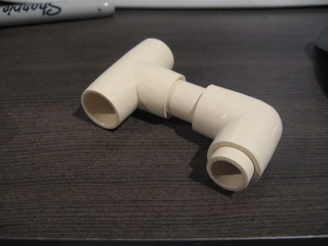
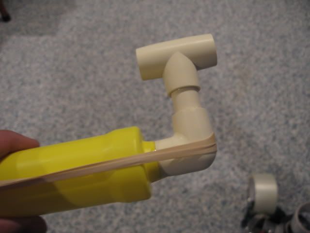
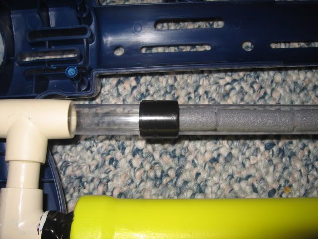
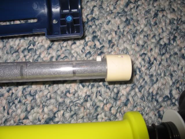
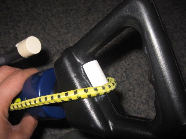
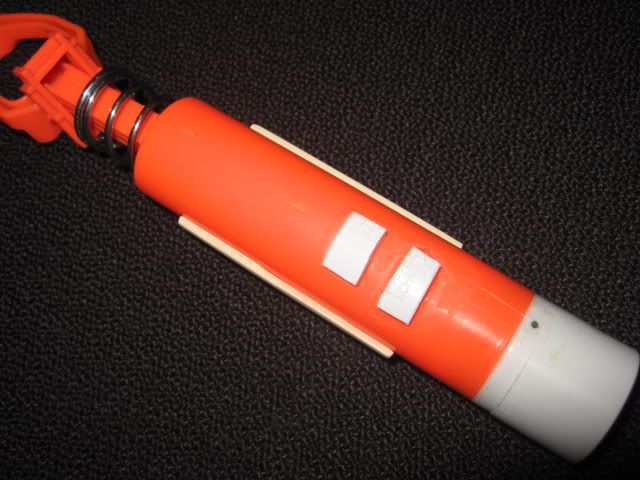
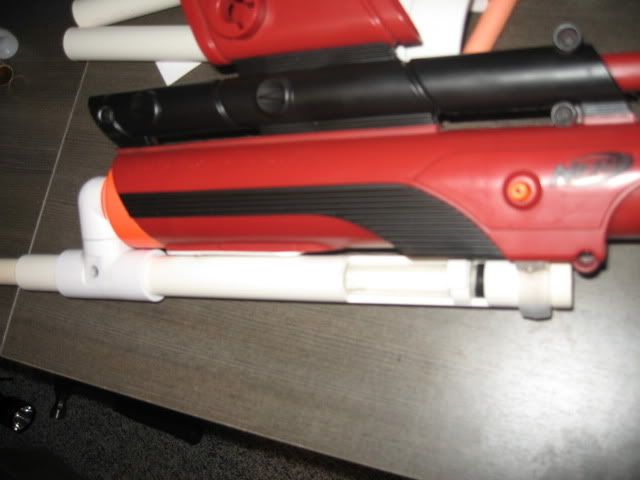
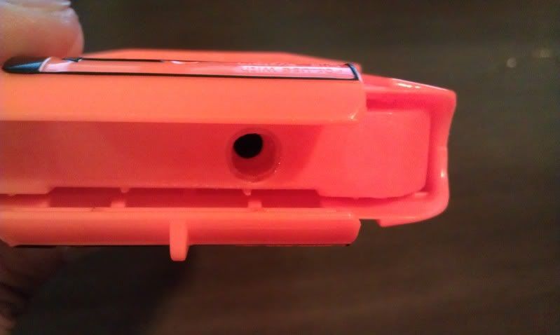
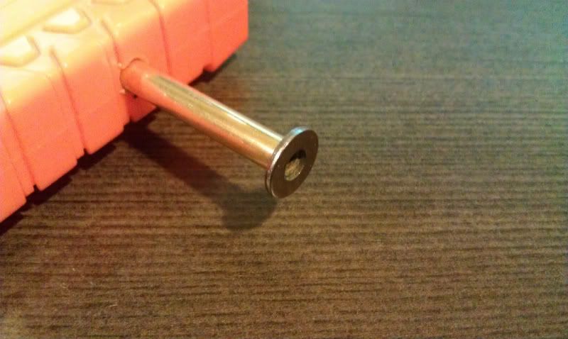
Add to this pump handle an o-ring that has a OD of 5/8 and you can nest PVC (wrapped in electrical tape) into the pump tube and keep the whole assembly intact.
#337051 Sodizzle Longshot v2
Posted by popatachi on 15 February 2014 - 12:02 AM in Modifications
In my cleaning, I found a longshot that I had intended to sodizzle. So I up and started in again and this time, was determined to make use of this Pak D clip. I won't go into detail about creating the sodizzle breach, but will explain what I've done specifically for this version. Please view some videos or a write-up to get more details on a sodizzle breach:
My sodizzle write-up
Sodizzle's video on his breach
Bolt
The bolt is really the tricky part. Once I got this measurement down, I adjusted the barrel to work with this length. This is really the part that you want to get working correctly before you determine the placement of your barrel. It has the usual 45 degree angle and is coned out to help with feeding. The lip of the bolt to the front of the plunger tube is 4.5" and probably another .5" that is embedded into the base of the bolt that is inside the plunger tube.
The bolt length may or may not affect the spring(s) that you are able to use as well. In my tinkering, I didn't have the plunger rod + spring when testing the length. When it was all assembled, I found the travel was off because of the spring, so keep that in mind if you are trying this out that you may have to tinker with this measurement based on your spring set up.
I am currently using a length of k18 spring.
Barrel
For the barrel I used a 10" length of CPVC. I wasn't able to easily use the stock dart tooth as a ramp in this version because the barrel had to be moved further back. I used Maverick AR's as spacers to get the correct placement of the coupler and used a cut down version of the stock dart tooth (ramp) to help feed darts. The ramp is glued directly to the coupler. In order to have the barrel not move backwards, a spacer will be used at the front part of the barrel. Here I am using a length of 2k pump that will be glued in place. I had to completing afix the barrel in place, so I am thinking of using another method so that the barrel can be removed if needed.
The seal of this is okay. It's not completely air tight around the coupler, but it's pretty close. I pondered attaching an o-ring within the coupler, but decided against it. Overall, this mod was to be able to work with the different clip, but I believe it will be able to work with both types of clips now. And apparently, I threw out the plunger head, so it's working with a make shift one at the moment. The seal is good, but hopefully I can find a stock replacement one soon.
Expanded and completed views
Close up of barrel and bolt
Close up of the front barrel
This is definitely not the cleanest mod, but I believe it works well and this time I had a better sense of what I needed to accomplish.
#313761 Foam backer Rod
Posted by popatachi on 30 March 2012 - 10:02 PM in Darts and Barrels
#211041 Bbb Help
Posted by popatachi on 10 February 2009 - 12:03 AM in Modifications
I was hoping that someone with a BBB could take a close up picture of their BBB when it is primed. Specifically, I am looking for a picture of the plunger area that will release the side locks once it has been fired.
I was adding hot glue to remove the dead space at the front of the plunger but may have added too much. And now I believe that the plunger is not going forward enough but I would like to know for certain. Here is the area in question:
The orange "nub" is part of the plunger and the gun has been fired. I would like to see where this piece is positioned on a working BBB and determine if that is the problem.
Any help is appreciated.
Thanks!
#211073 Bbb Help
Posted by popatachi on 10 February 2009 - 07:37 AM in Modifications
Thanks again.
#339741 Organizing nerf war in new hampshire
Posted by popatachi on 23 June 2014 - 09:31 PM in Nerf Wars
#261166 Problems With Nf
Posted by popatachi on 08 January 2010 - 08:07 AM in Modifications
If you're looking for a replacement, try Home Depot's #9713 springs. These are a little longer than the NF's spring so you will either need to cut it down a little or extend the draw.
#306691 Mav Paintjob Issues
Posted by popatachi on 29 October 2011 - 08:29 PM in Modifications
#312934 RFSG Help- rotation mech
Posted by popatachi on 16 March 2012 - 07:37 AM in Modifications
You need to have a pushnut fastner or something there to keep the rotation mech and turret seated together. There is probably too much room for the mech to separate from the turret and causing it to not rotate.
Once you fix those, you might as well fix the turret/plunger tube seal and put in a better spring combo to take advantage of the other mods.
#259161 Rscb Bow And Arrow
Posted by popatachi on 16 December 2009 - 01:11 PM in Modifications
I had also thought about trying to find a replacement plunger tube out of PVC? But didn't invest too much time into looking for one.
Overall, it is a fun blaster.
#263505 At3k Raider
Posted by popatachi on 28 January 2010 - 08:18 AM in Modifications
#201101 Longshot Replacement O-rings?
Posted by popatachi on 04 January 2009 - 06:16 PM in Modifications
There's a part list on this thread from Caption Slug. Look in the Quoted Area and it will give you the dimensions of the washers that you will need.
Link
But the basic breakdown is:
Plunger head replacement
#10 1-1/4" OD steel washer
#10 1-1/2" neoprene washer
#10 1-1/4" OD steel washer
#8 steel washer
#263415 At3k Raider
Posted by popatachi on 27 January 2010 - 03:14 PM in Modifications
This modification was made when the plunger tube of my raider exploded. Acquiring some AT3K's, it seemed like this was a perfect match. I didn't take any in-progress pictures, but I'll include what I can from the existing pictures. This was done without a plan other than to keep it simple. Much tinkering was done and each case will be different.
Here's my first experience tinkering with an air blaster.
MaterialsAT3K tank
AT3K pump or replacement pump
Raider
1 ft 17/32 brass tube
4" 9/16 brass tube
1/4" PVC
Spare CPVC/PVC
ToolsElectrical Tape
Glue (Zap-a-Gap and Plumber's Goop)
Dremel
Files
Sandpaper
Pliers
Step 1: Gut and Cut
Open up the raider fore grip and shell. You can remove everything except the jam door rails. The pieces you'll want to keep are: the front barrel cap, orange barrel, bolt sled, and the trigger assembly.
Determine how you want the pump to fit into the shell. If you use an AT3K pump, you will need to remove the bottom and front panels before the trigger. If you use a hornet pump, you can probably just remove some of the front area, but you will need to cut down the pump tube as it will be too long to attach to the raider's fore grip.
I added some PVC to the front of the pump that will still be inside the shell to keep it from moving out of the shell.
Cut and trim down the internals to get your pump to fit comfortably into the shell. Be aware of the outlet valve on your pump. I cut a hole through at the back for a valve opening.
Step 2: Prep the tank
Take the tank and remove all excess plastic from around the tank. You can use a Dremel to remove the majority of plastic, but switch to a file to shave off the rest. Be sure to clean the tank thoroughly of any plastic shavings.
Take the 1/4" length of PVC and glue this centered around the outlet valve. This will be used to secure the brass to the tank. For better adhesion, lightly sand both areas where the PVC and the tank will meet. Let this set and dry.
The inlet valve for the tank was too long to accommodate the vinyl tube and stay within the shell. You will need to cut the arm off after the 90 degree (the arm that points down when the assembly is seated), trim off a section and reattach the arm to the tank. I also trimmed off a couple of the barbs to shorten the length a little more. Test the tank to be sure you do not have any leaks.
There are a couple spacers and a spring on the pin. Remove the big spacer and the spring. The smaller one can stay or go.
Now take the bolt sled and cut off the top section leaving the bottom slide and some of the sides in tact and still connected. The tank will be mounted to the slide to better attach it to the shell and to make sure the outlet valve is lined up with the raider's barrel.
Attach the tank to the slide being aware that the intake value must be pointing down. You will need to trim down the slide until the tank fits snugly into the slide. Make sure that the slide touches the tank so it can be glued. I lined up the front of the tank with the front of the slide and cut the slide to fit up to the lip of the back of the tank.
Do not glue the assembly yet.
Step 3: Dry-fit
Take the slide and tank and tape them together and set it in place. Close your blaster shell and check the fit of the assembly. Also determine where you want the tank to be placed. I put the front of the tank in line with the back of the jam door opening. This seemed like a good location where the intake valve wouldn't get in the way of the trigger.
To further secure the tank, I added a back stop for the tank to rest against. This was a spare piece of CPVC that was wedged into the walls adjacent to the tank. Determine it's location when you dry fit the tank assembly, cut the walls and dry fit everything again.
Tape the assembly in place and look down the barrel to make sure that the outlet valve is fairly center in the barrel opening.
Step 4: Create the Breech
Take the 9/16" brass tube, add electrical tape and fit it into the PVC on the tank. Check that the length goes past the jam door. Center and make sure the breech is straight. Using a marker, mark the length of the breech. It should be a little past the PVC and up to the jam door. Use the maximum distance to account for whatever type of tab you will use to open and close the breech.
Cut the breech and file the edges smooth. Insert the 17/32" tube to make sure the fit is snug and that there are no leaks when the breech is closed.
Dry fit the breech into the tank assembly and determine the best position of the breech. Once that is set, remove the 17/32" tube and glue the breech to the tank and let that dry.
Step 5: Connect the pump
Open the blaster again and set in the pump. Determine the best path for the vinyl tube and cut away any walls that are in the way. Make sure there are no sharp edges or turns that could crimp the vinyl tube. Once you have the path opened, connect the pump to the tank and close the blaster.
Check the fit of the assembly too see if there are any more spots in the shell that need to be removed.
Step 6: Glue!
When everything is set, glue the tank assembly together and attach it and the back stop to the shell. Glue the vinyl tubing to the valves and let it all dry. Once it is dry, fill the tank with the pump to check for any leaks.
Step 7: Fore grip
Close the blaster shell with the pump. Add the fore grip and determine the stroke of the pump. You will want to try and use the entire fore grip's stroke to match the pump's stroke. I had to cut the back of the fore grip's rail to get the full range.
Make sure that the pump handle is centered with the pump tube and not angled in any way.
Cut and trim away from the fore grip to allow the pump handle to sit snugly. To attach, I drilled through the grip and pump handle and ran a thick wire through. I made a bend in one end (like an L) and made a second hole in the handle for to secure the pin. This will still allow me to remove the grip.
Test the pump and keep checking for leaks.
Step 8: Trigger
Open up the blaster and add the trigger and it's spring. You will need to make two bends in the firing pin. Get a straight edge and line it up parallel with the angle of the trigger. Where the straight edge and the pin intersect is where you will make the first bend. This bend should put the pin parallel and right next to the trigger.
Mark the spot on the pin and using some pliers, make the bend and line the two up. Make sure there is not too much tension on the pin as it could result in the outlet valve not closing all the way allowing air to escape.
Next mark the spot right on the pin after the trigger's angle. This is where you will make the second bend. This bend will allow the pin to rest inside the dart chamber in the handle. You will need to cut the wall to make sure it fits but will not come out. This is the pivot for the pin that allows the pin in the tank to be pushed by the trigger.
If there is too much tension on the pin, trim the trigger rather than trying to re-bend the pin.
Close the shell and test the trigger. (and leaks)
Step 9: The Barrel
For the barrel, I glued the Raider's orange barrel to the front cap so it will not move. Once this is installed, get the 17/32" barrel and add electrical tape in two areas of the length. This will help to stabilize the barrel. Make sure to not add too much tape. You will want the barrel to be able to slide smoothly and easily through the orange barrel. Too tight a fit could break the breech tab.
Set the barrel into the breech and close it. Create the tab and carefully glue it to the 17/32" barrel near the back of the breech. I used a length of CPVC that would extend past the shell and cut a small piece of PVC the length of the CPVC. I curved out the CPVC to fit onto the PVC and glued that together. Then, glued the tab onto the brass.
Let that dry and test the breech. (and leaks)
Step 10: All Done
Close up any gaps and add all the cosmetics you want. The clip slot on mine will either be removed and closed or drilled out on the top to keep darts for easier reloading.
Here is a short Firing Video
Enjoy!
UPDATE: Shell modifications all done:
Clip slot removed and covered
Breech tab closed and breech area closed
Pump area closed
Ranges: Average 95ft with single BB stefans
#259036 Rscb Bow And Arrow
Posted by popatachi on 15 December 2009 - 12:26 AM in Modifications
@Blue: thanks! This thing is a lot of fun, I can't wait to try it out doors.
#259015 Rscb Bow And Arrow
Posted by popatachi on 14 December 2009 - 09:53 PM in Modifications
Credit to Fome for the original writeup.
Video Review
Materials:Bow and Arrow
CPVC coupler
CPVC tee
1 1/2" length of CPVC
3/4" length of CPVC
9" length of CPVC
1 CPVC end cap
10" length of 5/8 PETG
2" length 1/2 PETG
1 Screw
1 Bungee cord
2 ScrewsTools:Hack saw
Dremel
Files
Sand paper
Glue (Goop and hot)Step 1: Disassemble the blaster
Remove the eight screws and open up the blaster. Take out the plunger and plunger rod and inspect everything for cracks, chips or any signs of wear.
Step 2: Modify the plunger head
Different models of the Bow and Arrow have a different plunger head. Here is mine. You have to remove two white plastic pins in order to remove the plunger head.
Flare out the plunger and add some hot glue to help increase the seal.
Saw off the small white cap at the top and glue one some foam to help pad the plunger and fill the space with hot glue.
Connect the plunger assembly. My Bow and Arrow only had one white cap, so I opted to use a screw to hold the assembly together.
Step 3: Modify the blaster shell
In order to minimize as much dead space as possible (because there will be some already with the height) I opted to attach the RSCB as close to the plunger tube as possible. This meant cutting the shell to allow the CPVC to be closer.
Cut off the top front area of the blaster and widen the hole to the plunger tube. Use the inner walls of the blaster as your guide. Sand smooth and round the edges. Test fit your CPVC elbow to make sure it will fit properly when the blaster is closed. I also sanded the sides of the CPVC elbow to help with the fit.
Step 4: Create the RSCB assembly
Close the blaster and insert the CPVC elbow into the front opening. Take your 1 1/2" CPVC length and insert that into the elbow and attach the tee to the top. Make sure that this assembly is straight and is lined up with the hole in the top handle. Take the 3/4" length of CPVC and add that to the other end of the elbow.
When you are satisfied with the fit, put it aside.
Step 5: Cut down the existing barrel
Take the plunger tube and cut off the plunger tube that accepts the arrows. This is about 1/4" away from the plunger tube, but it may vary depending on your CPVC. I ended up cutting about 3/4" and then filed the tube down dry fitting the elbow and plunger tube into the shell to make sure of the fit.
To help stabilize the RSCB assembly, add hot glue in the shell and a couple of tabs to the elbow to keep the assembly secure.
(The tabs are partially hidden by the electrical tape.
Step 6: Dry fit, glue, re-assemble
Put everything minus the plunger rod together and turn it around and around. Make sure that everything is how you want it to look.
Now take out your glue and glue the RSCB assembly, and when that is dry, glue the assembly to the plunger tube. Because the plunger tube is a soft plastic, give it a generous amount of time to dry and use a lot of goop and then wrap in electrical tape.
Step 7: Add barrel and dart chamber
For the dart chamber I was able to find 5/8" outer diameter PETG. This is the same diameter as CPVC and it fits OMC's PETG very tight. Add this to the CPVC tee, add a cap, and make a breech in the back to be able to load darts. Once dry, glue this to the back of the tee. This particular dart chamber can hold seven 1.5" stefans.
For the barrel, make sure to cone out the back of the barrel so that darts fit about 1/4" into the barrel. Attach and glue this to the front of the tee.
Step 8: Add bungee cord
In order to add a bungee cord, some reinforcements are needed. Take the 2 screws and cut them down to fit into the slots seen in the pictures below. Cut away the middle slot, drop in the screw and add hot glue around the slot and below that one as well.
Get your bungee cord and check the fit. I had to remove the rubber from the hook in order to get the hook to sit flush with the blaster shell.
On the handle, cut some spare piece of PVC and glue it to the top of the inside of the handle. This will help to keep the bungee cord straight as you draw back the plunger.
Step 9: All done!
The picture doesn't have the pink arms, but those will get attached with no modifications.
I don't have ranges yet. I'll post them when I get to it.
I would definitely recommend reinforcing the bottom handle as it can and will break over time. I haven't done it yet, but here's link to a thread the fixes it post-break. Bottom handle fix
#324056 Need help!
Posted by popatachi on 01 December 2012 - 10:53 PM in Nerf Wars
#326867 Doomsayer plunger head
Posted by popatachi on 15 February 2013 - 10:23 AM in Modifications
Venom's Thread
#347748 Help finding post on specific mod
Posted by popatachi on 07 July 2015 - 08:05 PM in Modifications
#250303 Raider Cs-35 - Dart Tooth
Posted by popatachi on 13 September 2009 - 10:11 AM in Modifications
@Lt. Stefan: Yeah, it's not going to give you a significant boost, but every little bit helps.
#259619 Nite Finder - Closing The Gap On A Minimized Shell
Posted by popatachi on 23 December 2009 - 12:45 AM in Modifications
MaterialsNite finder
1 mm thick plastic styrene (Brands include Plastistruct or Evergreen and can be found in most hobby shops)
- The styrene I purchased came in a pack of two 1mm sheets that are 12" x 6" in size for about $5. Here is a link to www.towerhobbies.com that sells it and so you can see the product.
ToolsSharp Blade
Glue (Zap-A-Gap)
Zip ties (a lot of them)
Files
Sandpaper
Dremel
Step 1: Minimize your blaster shell.
I opted to remove the top rail and front light. Make sure to sand the down the areas to be smooth.
Step 2: Prepare the styrene.
Cutting styrene is really easy. Just score the cut line with a sharp knife a couple times and you can snap it off by bending the styrene at the cut mark at the edge of a table. For each of these areas, I cut wide of the measured mark and sanded down to the desired point. This was done so I didn't undercut any areas and have to trash any pieces. Be sure to measure as your dimensions may be different.
Top rail: 13/16" x 4 3/16" (I cut about at most about 1/4" wider than the finished dimensions). This was then cut in half and marked to know which ends connected.
Front: This was done in two sections. Underneath the barrel and around the trigger guard.
- Underneath: 15/16" x 14/16" (because this was not a straight section I left it complete and cut it once glued to make sure the middle area didn't warp)
- Guard: 1 2/16" x 2 1/2" (also complete and cut after glued)
Once you have your styrene cut, lightly sand the area that will be glued to the blaster shell. This will help the styrene adhere better.
Step 3: Glue!
Remove the internals of your nite finder and close the shell. Starting at the top, place a small amount of glue on the top shell making sure to not get too much around the join of the shell. Take one side of your styrene and line up the inside of it with the join in the shell on both ends and press firmly. Quickly take the other side, making sure your match marks meet, line it up, press it down firmly.
Let this sit for a couple hours.
NOTE: I tried using a heat gun to get the bend right, but the plastic warped too much and I wasn't able to get it uniform.
Get your zip ties ready.
I started with the trigger guard since that was going to be the most difficult. Place a small amount of glue along the front of the guard and a little around the corner. Quickly place down the styrene press firmly. In a couple minutes, slowly bend the styrene around the guard making sure that the front area doesn't move during the bending process. Once you have the styrene bent relatively well, put some glue along the bottom, again be careful not to get too much by the join, and press down firmly.
Now grab your zip ties and start wrapping them around the guard. This will hold down the styrene to the shape of the guard. Make sure to get the zip ties tight and to pay special attention to the curves. You can use spare styrene underneath the zip ties to help keep the styrene straight and tight against the shell.
Let this dry overnight.
Once the guard is dry, remove the zip ties and inspect the styrene to make sure it fits correctly. Using your knife and a bendable ruler, lightly score a join down the entire length of the styrene. Go light and easy making multiple light passes rather than one heavy pass. In a couple minutes, the styrene will separate.
Now follow the same process for the area underneath the barrel.
Once all the areas have been covered, open the blaster and add glue to the interior of the shell for further strengthening the bond of the styrene to the shell.
Step 4: Sanding
Now that you have the shell covered up, use your dremel/files/sand paper to reduce the styrene to fit the shell any way you see fit.
Step 5: All done!
This process can work for any blaster shell and just takes time, patience and an abundance of zip ties.
Extended Draw
For the plunger, I glued on a PVC end cap and drilled through the cap to create a coupler and added a dart stop wire made from a paper clip. I then widened the hole in the front of the blaster to allow the PVC to fit.
To extend the draw, find the point where the plunger rod almost hits the outside of the shell and make a mark through the outside of the shell onto the plunger tube. These marks can be used to add CPVC strips to the plunger tube to secure it into the shell. I also added some supports for a post but that wasn't completely necessary.
In order for the front of the shell to close properly, I found a 1" post at Ace Hardware for the guard and cut one of the existing posts from the Nite Finder's front area for the top of the shell. The second picture doesn't show the top post.
If you have any questions, reply and I'll try to answer them as best I can.
Ranges: Averaged 75ft with a single BB stefans.
#250246 Raider Cs-35 - Dart Tooth
Posted by popatachi on 12 September 2009 - 07:17 PM in Modifications
This is because the dart tooth starts to move down when it is in contact with the bolt sled. There is a small arm at the bottom that pushes the dart tooth down. If you trim these two pieces down, they won't make contact until the priming sequence is near the end and pushes the dart further into the bolt rather than having it half in the bolt, half in the chamber.
Hopefully this picture will help.
This is the dart tooth and the arm on the bolt sled.
For reference, here is a picture from the raider over haul thread (thanks SPV999).
One thing to note, be careful how much you trim off the dart tooth. Trimming too much or at too steep an angle won't allow the top of the dart tooth to clear the bottom of the chamber tube. In my modification, the top is just about flush with the chamber. So make sure to try and keep the same angles.
Enjoy!
#250254 Raider Cs-35 - Dart Tooth
Posted by popatachi on 12 September 2009 - 08:36 PM in Modifications
Here's a quick video I took. I primed the raider up until the last moment before it locks. And you'll see that I push on the dart showing that I'll all the way back in the bolt. Sorry I didn't take a video or pics pre mod.
#325039 My personal pic
Posted by popatachi on 03 January 2013 - 01:41 PM in Site Feedback
There's an old post that still applies on how to do it: Google Site Search
Anyway, hope that helps if you haven't tried that already.
Thanks for the fix, Langley!
#347756 Help finding post on specific mod
Posted by popatachi on 08 July 2015 - 12:05 AM in Modifications
Very cool mod. Reminds me of my 3k raider. I hope you found what you're looking for in your build.
#259621 Nite Finder - Closing The Gap On A Minimized Shell
Posted by popatachi on 23 December 2009 - 12:54 AM in Modifications
#347750 Help finding post on specific mod
Posted by popatachi on 07 July 2015 - 08:33 PM in Modifications
http://nerfhaven.com...showtopic=19880
I thought there was a way to search a history of your views, but only posts and threads. You could try to look through your browser history to see if the thread was saved there? Any idea of the user to did the mod?
#259670 Nite Finder - Closing The Gap On A Minimized Shell
Posted by popatachi on 23 December 2009 - 08:11 PM in Modifications
Some light scoring would definitely work with really sharp or narrow curves and corners though. Thanks for the extra thoughts, that is useful to keep in mind.
#259919 Photobucket Issues
Posted by popatachi on 27 December 2009 - 09:28 PM in General Nerf
#255387 Rscb Bbb
Posted by popatachi on 05 November 2009 - 01:07 PM in Modifications
@berserker: When I first tried this out, I kept tipping the blaster up to see the barrel, but I am getting use to the idea that I don't need to see the barrel to aim. As long as the RSCB is straight, it's just a slight adjustment when aiming.
#255378 Rscb Bbb
Posted by popatachi on 05 November 2009 - 11:53 AM in Modifications
@k9turrent: I totally did! I used a combination of yours and Mr. BadWrench's write ups on RSCBs to help me work through this thing. Thanks!
#255372 Rscb Bbb
Posted by popatachi on 05 November 2009 - 11:11 AM in Modifications
For this modification I wanted to try and reduce as much dead space as possible and still get an easy to load RSCB.
Materials:Big Bad Bow
1/2" PVC elbow
1/2" PVC Tee
1/2" PVC tube (6 3/4" for darts, 2" to nest barrel, 1" for connection)
CPVC tube (6" for barrel, 1/2" for connection)
CPVC end cap
PETG (for breech or another material)
PVC clip
Extria screws
Tools:Dremel
Zap-a-Gap
Plumber's Goop
Files
Electrical Tape
Step 1. Modify the front cap, ring, and elbow
Most modifications start with attaching a coupler to the front cap and nested CPVC into the barrel and filling the dead space with hot glue. I opted to try a different method of attaching the PVC elbow directly into the front cap. This will reduce the dead space and not require a lot of hot glue in the process.
To do this, you will need to cut off the exposed area of the front cap and widen the hole in the cap until the PVC elbow can slide through. Try to get a good fit and not widen the hole too much.
The white ring that was part of the air restrictor was used to help support the PVC elbow. The hole had to be widened just a bit to be able to accept the elbow. Once the PVC elbow can go through the ring, glue the ring to the front cap. Be sure that the ridge is facing the front to the cap.
I used goop in the front of the ring and Zap-a-Gap at the back to make sure no air can get through.
As for the PVC elbow, I had to file down the inner area to allow the elbow to reach a little further back into the cap.
In the above photo, notice on the left side of the PCV wall with trimmed straight. I did this to both the elbow and the tee just so that it matches.
Step 2. Modify the BBB Shell
There are two areas that need attention. The bottom of the barrel opening and the front handle.
I removed the bottom lip of the barrel opening to allow the PVC elbow to get even further down into the plunger tube so it can be as close to the plunger head as possible.
The front handle was removed so that the PVC that will hold the darts can be added in this area. Sand the area flat. The front handle will not be used and can be discarded or saved for future modifications. Optionally, you can move the location to the RSCB barrel to above the blaster if you want to keep the bottom for an integration.
Step 3. Create the RSCB
To remove more dead space, take the PVC elbow and cut half of the tube that will connect to the PVC tee and do the same to the middle tube on the PVC tee. Make sure to get these as straight as possible.
Take your 1" connection PVC tube and dry fit these pieces together. When you are satisfied with the fit, use goop or Zap-a-Gap to secure the assembly.
You have different options for your barrel, but I opted to use a 7" length of CPVC nested in a 2" length of PVC. The important part of the barrel is to cone out the end that will be put into the PVC tee. I used a dremel to cone out the CPVC enough to allow a dart to fit in about 1/4". Once you have your barrel, dry fit this into the PVC tee.
Now take the 7" length of PVC and attach that to the other end of the PVC tee. Take the CPVC end cap and cut it in half. You may need to dremel out the inside if there is a ridge at the back. Take the CPVC connection and glue it into the end cap. Attach this cap to the PVC dart barrel. It should have the same diameter as the PVC.
I opted to create a breech so that I wouldn't have to pull the barrel off to reload. Cut a 3" hole into the tube, nest PETG with electrical tape wrapped around the ends and glue on a tab.
In order to quickly see if there's a dart in the barrel, drill two holes through the PVC tee and cover these with plastic and secure with glue.
Take your RSCB and dry fit this into the BBB shell.
Step 4. Glue
You don't need to glue the barrel and/or the dart holder if you want to be able to remove either of these pieces.
Now take the assembly and glue the elbow to the white ring in the BBB's front cap.
Step 5. Seal it up
I added electrical tape between the front cap and plunger to keep air from escaping. I also added some glue between the elbow and front cap at the opening for a little more stability.
Attach the PVC at the end of the dart barrel to stabilize the PVC. I also used some scrap plastic from a VHS box to help secure the front of the shell as well.
Step 6. All Done!
At this point the mod is complete.
I was going to add a front grip with a 2" PVC but the connection point with the shell didn't have enough room for screws. So I'm looking into some rubber door stoppers to add to the sides of the shell to be able to grip the blaster as I'm priming it. In the meantime, you can hold the back of the front blaster to prime.
Ranges:
With a shorter barrel (6") and better plunger seal (flared out the plunger head) I am averaging 75ft with single BB stefans.
#254894 Rebarrelling Buzzbee Belt Blaster Shells
Posted by popatachi on 29 October 2009 - 08:05 PM in Modifications
#314419 stefan stampede clip
Posted by popatachi on 15 April 2012 - 10:55 PM in Modifications
NOTE: This method can work on a 6-dart clip, but you need to determine where the center coil is located and put the post on the other side of the clip. This may mean that you must reverse the clip (cut off the top tab and add a clip lock slot on the opposite side of the clip) in order to use the clip in your blasters.
The Youtube Video
MATERIALS:
- 7/32" brass tube or compatible rod/tube (longer than a stampede clip ~ 11")
- ~1/2" length of a pen (this will act as a sleeve to the above tube)
- paper clip
- stampede clip
- #6 or #8 washer or something compatible
TOOLS:
- drill or drill press
- round file
- 7/32" bit or one that will fit the size you have
- pin vice or bit that is small enough for a paper clip
- glue
ANOTHER NOTE: long ago when placing an order for brass tube, I accidentally ordered 7/32" tubes instead of 17/32". Years later, I'm glad that I kept them around.
Step 1: Prepare the clip
You will want something to slide and hold the dart pusher all the way down at the bottom of the clip. I had a piece of plastic tubing, but anything will do. With that securely in place, drill a tiny hole through the shell and dart pusher. For this I use a pin vice or a hobby hand-drill with a small bit. Either way, the hole should only be wide enough to allow a straightened paper clip through. This will lock the dart pusher in place.
Alternatively, if you have a method to secure the dart pusher in place without having to drill the hole, you can do that too.
Step 2: Drill it!
Mark the location for the post. The location would be the same spot where you would normally glue the side rails allowing for your darts to rest comfortably. Make sure to use the same diameter bit as your rod/tube. You will want the shell hole to have a snug fit where the dart pusher hole will need to be widened to accept the sleeve. Either way, drill through the shell and dart pusher.
Step 3: Add a sleeve
(This sleeve is fairly clear and a little hard to make out)
Release the dart pusher and insert the rod through the bottom of the shell and prop up the dart pusher so that it cannot slip down. With this secured, widen the hole in the dart pusher to accept the sleeve. Make sure that the sleeve that you choose will allow the rod/tube to easily slide. This should not be a snug fit at all. Once the sleeve is in place, secure it will glue and file/sand the top of the dart pusher.
Step 4: Cutting of the tube
Set the dart pusher to the lowest point with the side of the clip. This is where you will want to set the top of the tube/rod. Since this is the point where the dart tooth/barrel will be resting (hence why you need the sleeve). Once that location is set, mark the tube where the excess is sticking out of the bottom of the clip. Cut this excess off and glue a washer on.
Step 5: All Done!
Insert the rod and now you have a stefan/stock stampede clip all without having to chop the clip open. Enjoy!
The Youtube Video
#314423 stefan stampede clip
Posted by popatachi on 15 April 2012 - 11:16 PM in Modifications
#260063 Turreted Pistol Splat
Posted by popatachi on 29 December 2009 - 08:16 AM in Modifications
You might also try to shorten the barrel. When I tried my inline clip with a 4" barrel and a 4" clip, the darts were barely able to leave the barrel. Once I shortened the barrel to 3" and the clip to hold two darts everything worked fine.
#314433 stefan stampede clip
Posted by popatachi on 16 April 2012 - 07:23 AM in Modifications
And good point about tape! Although there must be a simple mechanical way to hold everything together... I'll have to think on that more.
#324842 Lock N' Load Returning Priming Slide Mod
Posted by popatachi on 28 December 2012 - 02:55 PM in Modifications
#324845 Lock N' Load Returning Priming Slide Mod
Posted by popatachi on 28 December 2012 - 07:13 PM in Modifications
#334862 Painting
Posted by popatachi on 16 October 2013 - 08:02 PM in Modifications
Chipping and wear is normal for areas with moving parts though the different types of paint may help to increase the time the paint stays. The dye gets fairly decent results where normal paint will sit on top of the plastic and is more prone to being chipped or worn off.
There's no perfect solution though. Good luck!
- NerfHaven
- → popatachi's Content
- Terms of Service and Privacy Policy
- Code of Conduct ·