Find content


Background:
Original thread: http://nerfhaven.com...showtopic=23437
ESLT 1.0: https://sites.google...er---3d-printed
ESLT 1.5: https://sites.google...1-5-build-guide
Clear ESLT Demo: https://www.youtube....h?v=lz9rx-qmZmE
The first ESLT was built 2+ years ago, and a lot has changed since the original. This is the latest version MHA is producing, and the design will continue to evolve from here. A 3D printer is required to make these blasters unless you are clever enough to substitute all the printed pieces with something else. It's definitely possible, as many people have already done this, including ourselves. The 3D printed version is obviously a lot easier to build if you have the necessary tools.
This blaster is designed for 5.5" of draw.
Changes since 1.5:
-New printed angled pump grip (replaces reducing tee)
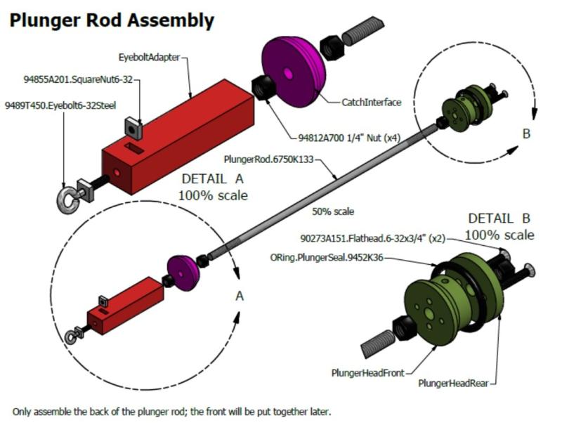
-Eyebolt changed to a steel one
-New ReDirectPiece and o-ring holder
-Changed plunger rod material to anodized aluminum
-New BarrelSpacer to accommodate pump grip
-MainHandle more angled for comfort
Downloadable Files
Click Here
39 MB
Contains everything you need, stl's for printing, stp's for modeling, and a parts/cost sheet.
.ipt files are compatible with Autodesk Inventor 2014 or newer.
Essential Tools
-3D Printer w/ no less than 7x7x7" print area
-Scrollsaw or Hacksaw
-Drill press and/or power drill
-Dremel w/ cutting wheel or Mill/Scrollsaw
-7/64”, 5/32", .260" (or slightly over .250), 1/2", 5/8" drill bits
-#6-32 tapping bit
-1/4-20 tap and die set
-5/16-18 tapping bit
-Scissors and/or file
-Screwdriver
-Countersink (Any size, really)
-Hot glue and/or super glue
-Duct tape
-Silicone lube
-Safety glasses
-Vise and/or wrench
-Tape measure/ruler/calipers
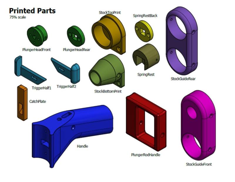
Printing your Components
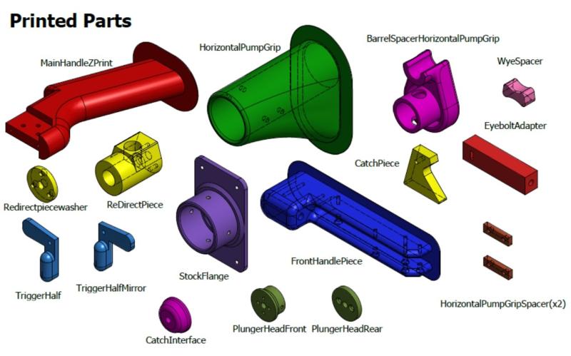
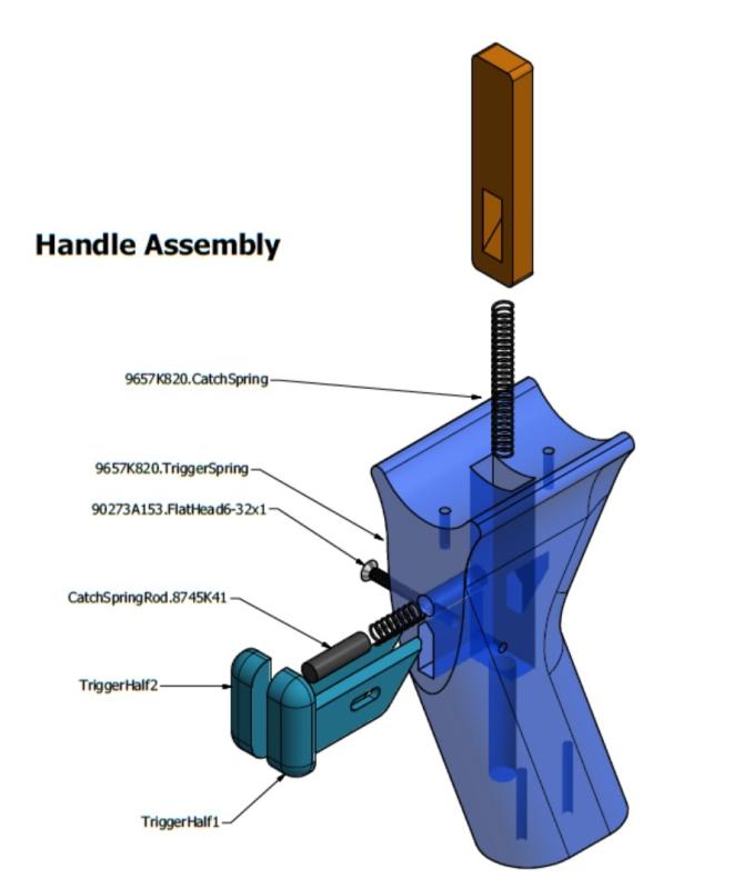
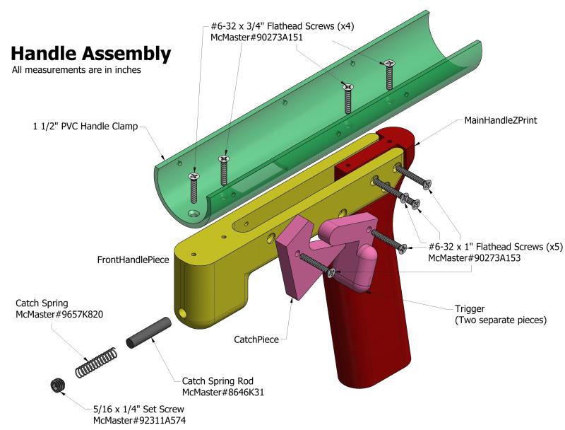
MainHandleZPrint/Halves - This is the part of the handle you physically hold. There are two ways to do this. You can do it vertically, like we do, or you can do it in two halves and glue them together. If people don't have printers that can print up to 160mm in the Z axis, you'll need to do them in halves. Layer adhesion is the weakest point on parts that come off these printers, so extra/thicker perimeters are a must if printing vertically. A larger nozzle is preferred. Post-print you'll have to tap the two holes (#6) at the top of the print where it attaches to the HandleClamp. You also may need to drill out the three holes (#6 clearance), where it attaches to the FrontHandlePiece.
FrontHandlePiece - This is probably the most challenging print on the blaster. They are pretty long (175mm) and will warp at least a little bit unless you really have your settings on your printer super fine tuned. I've found adding lots of brim helps, especially adding brim to your model so the brim is actually attached to the printed part for a layer or two. Post-print you'll need to tap the two holes (#6) where it attaches to the HandleClamp. You also may want to drill out the two holes (#6 clearance), where the CatchPiece and Trigger are mounted.
HorizontalPumpGrip - This is the aforementioned new add-on. It replaces the reducing tee which was heavy, expensive, and a lot of machining required to get it to work. We usually print these with a few extra perimeters, and is now the biggest print on the blaster.
CatchPiece; CatchInterface - The CatchPiece is basically the catch of the blaster (hence the name), where the CatchInterface is more like the "catch notch" in a normal blaster. These two pieces need to be 100% infill since they see a lot of wear during use. Post-print you'll need to tap (1/4) the only hole on this piece.
Trigger3DPrint/Mirror - These don't really don't matter how they're printed. You'll need to glue the two piece together after they are printed. After they're glued together, drill out the hole (#6 clearance).
ReDirectPiece - This piece sees a lot of wear since the plunger head is smashing into it each time it's fired, so it's printed at 100% infill. After it's printed, drill out the hole for the CPVC stub (5/8"), and drill and tap (#6) the three new holes on the bottom of the piece.
ReDirectPieceWasher - This is a new piece that sandwiches the rod seal o-ring against the ReDirectPiece. We usually print these at 100% infill to be safe, and they're small pieces. Drill out the three holes (#6 clearance).
HorizontalPumpGripSpacer(x2) - These replace the old PumpGripSpacer, and need to be 100% infill. Drill out the two holes (#6 clearance). They are much smaller and easier to print than the old version.
EyeboltAdapter - The Eyebolt Adpater needs to be strong and is a quick print with a larger nozzle. The new adapters are fitted for a #6-32 steel eyebolt, as opposed to the #10-24 or 1/4-20 nylon ones we used to use. Post-print, you'll have to tap one end with a 1/4-20 tap, and the other end uses a square nut and does not need to be tapped.
BarrelSpacerHorizontalPumpGrip - The newly added printed pump grip, meant we needed to make some extra space near the front since it's much longer than the reducing tee. This new print fits inside the front end of the FrontTube as well as the outside. More perimeters is probably a good idea for this print as barrel spacers are always prone to getting damaged.
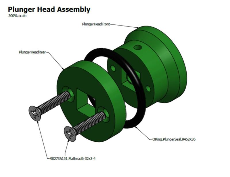
ESLTPlungerHead (Front/Rear) - More information on these can be found here. You'll need to tap (#6) the two holes in the front piece that connects the two. The back piece should be drilled out with a #6 clearance hole. Both also need to be tapped (1/4-20) to attach to the plunger rod.
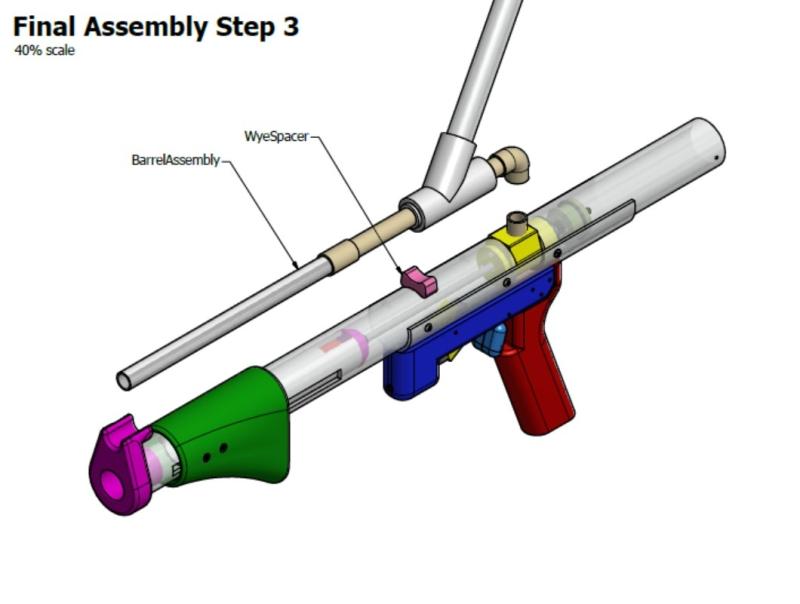
WyeSpacer - Also another print that doesn't have to meet any specifications. This print simply gives you a wedge in between the wye and the front tube to tape the barrel assembly from wobbling.
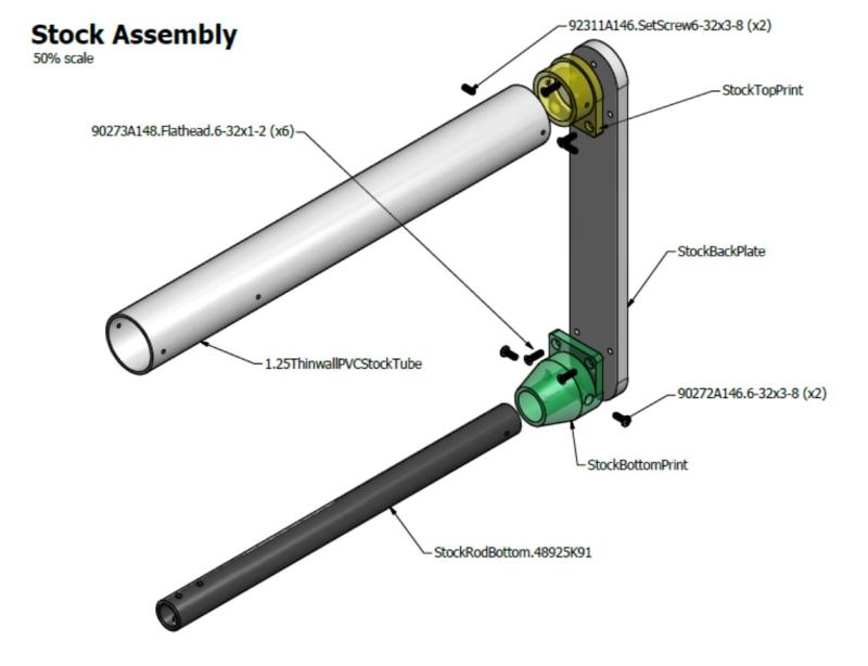
StockFlange (optional) - If you have a printer you might as well do this piece. It attaches the plunger tube to an HDPE sheet which is hot glued to a piece of foam, for comfort. This is a highly recommended add.
Tube & Rod Machining
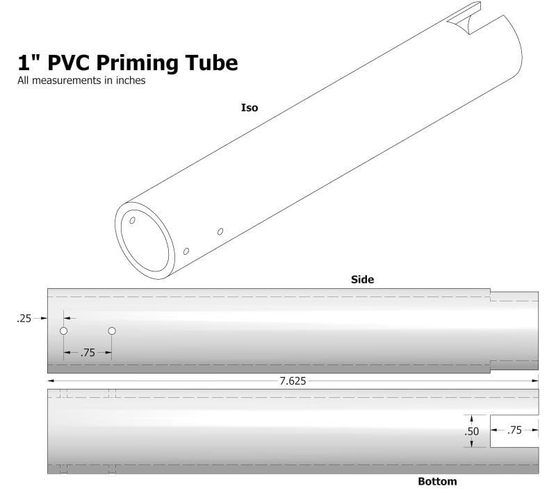
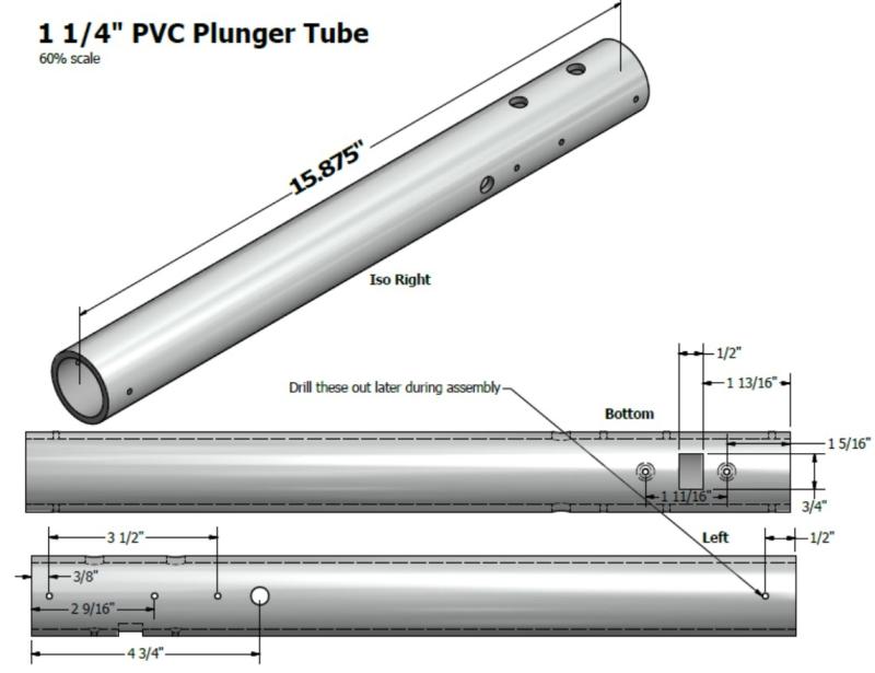
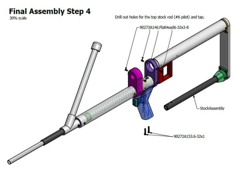
The Priming tube is the linkage from the HorizontalPumpGrip that pushes on the CatchInterface, which pushes back the plunger rod. You can scrollsaw, mill, or dremel the bottom slot. The holes should be 7/64" or a #6 pilot, and need to be tapped afterwards. These need to be fairly centered holes so the 1" is mounted centrally inside the 1 1/4" front tube.
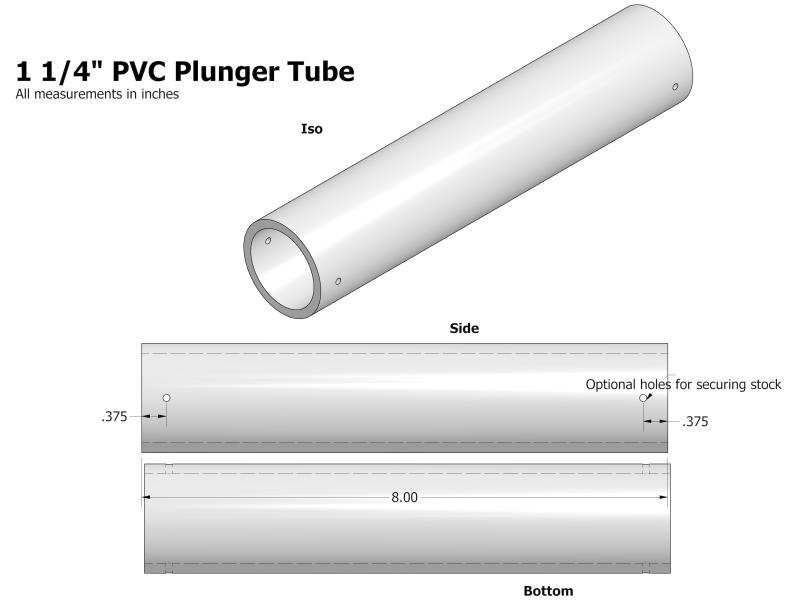
Make sure your PVC is smooth on the inside. The majority of PVC we encounter is very bumpy and awful on the inside, creating unnecessary friction and a shitty seal. The holes will be drilled after you've inserted and attached your ReDirectPiece and Stock.
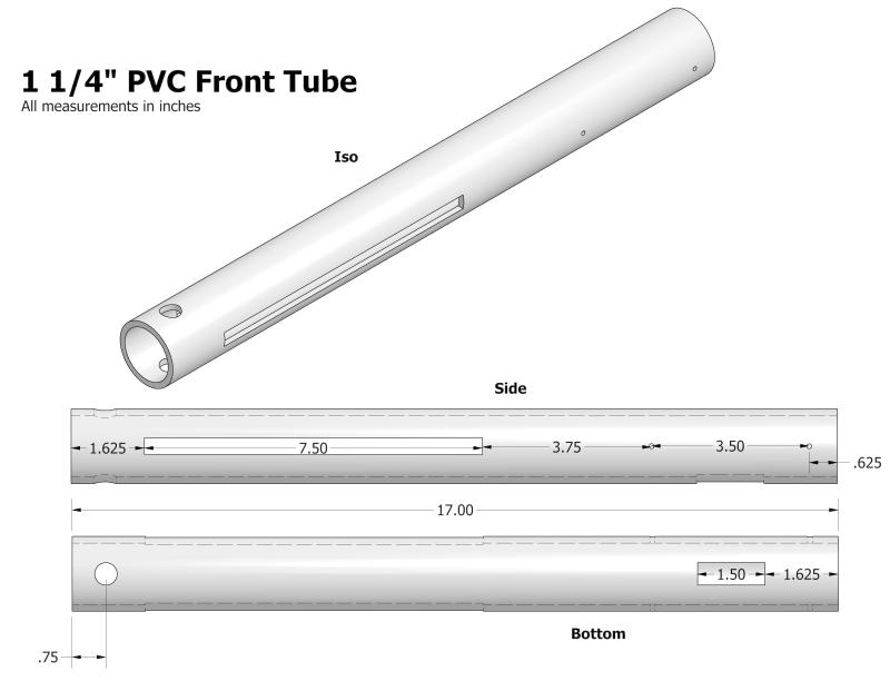
The biggest tube to machine, and requires some pretty long slots. We do these on a mill, but a scrollsaw is probably the next best option, followed by a Dremel, which is pretty terrible. The slot should be at least 3/8" wide, if they are centered. If they're off, they'll like need to be oversized. The holes should also be #6 pilot holes and drilled after you've assembled some stuff. Again, this will be explained more later. The larger hole in the front is 1/2" in diameter which holds the spring post. You'll also need a slot on the bottom for the CatchPiece to clear.
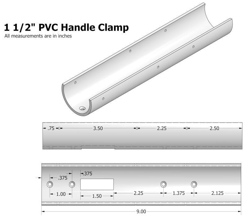
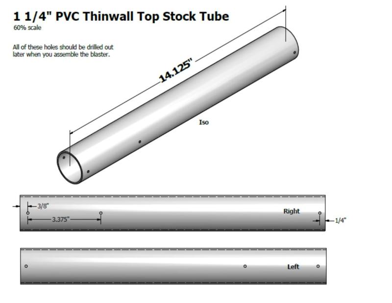
These are basically a tube cut almost in half, leaving one side to be a little more than a half tube. This will clamp over/slide over your 1 1/4" tubes, and connect your handle to them. It needs a 1/2" slot in the bottom, with 5/32" or #6 clearance holes to attach to the handle. They also need to be countersinked. The holes near the top of the clamp should be #6 clearance holes, and you should drill them before cutting the tube in half.
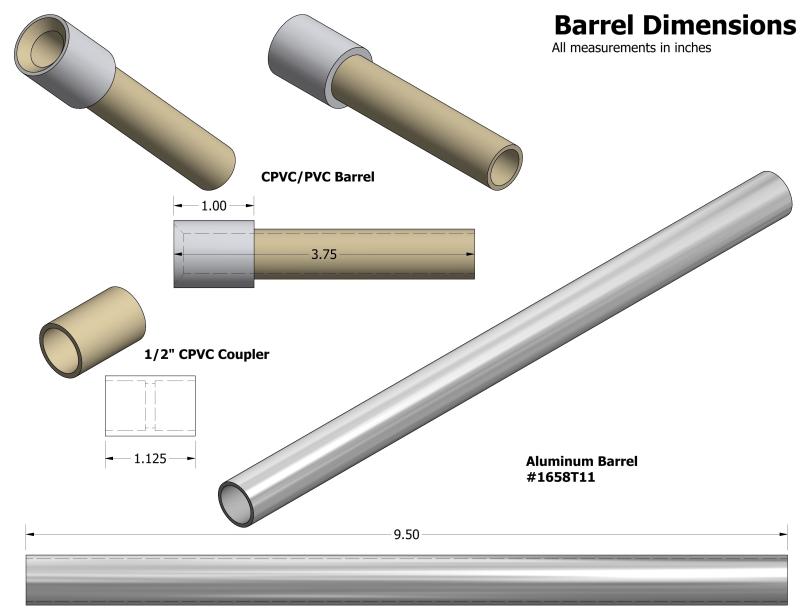
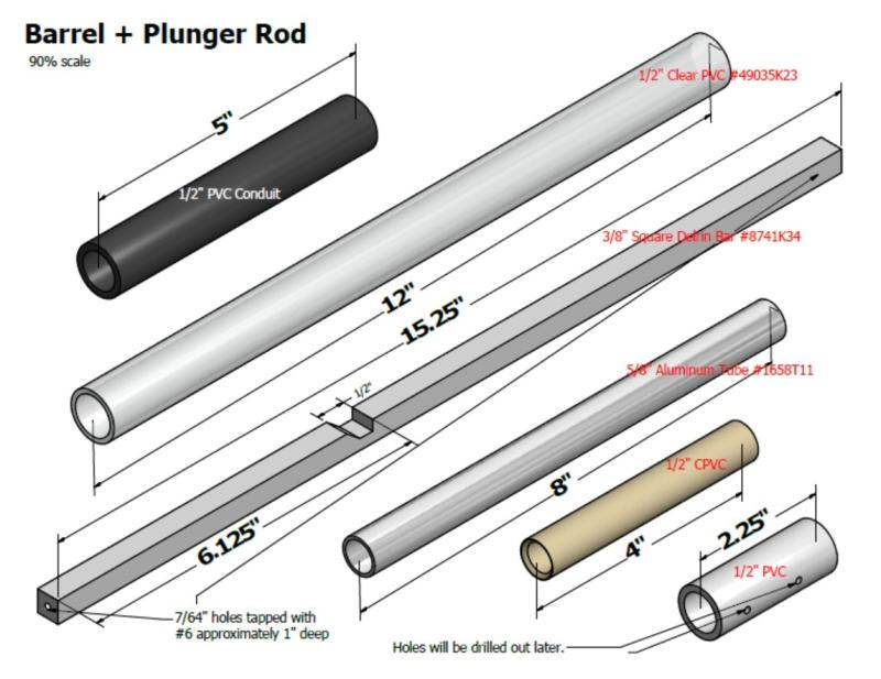
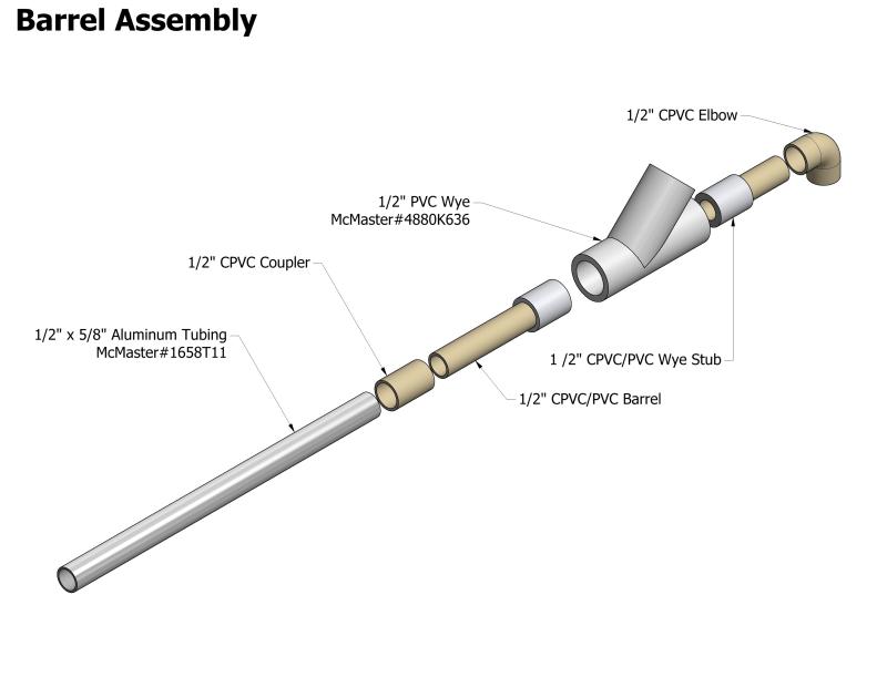
Pretty straightforward here, make sure you chamfer the CPVC/PVC barrel combo to allow a smooth feed for the the darts. Instead of using a CPVC coupler, you can also use a length of 1/2" PVC drilled out to 5/8", or magical conduit that cheerios finds at Menards. Make sure you super glue your CPVC/PVC barrel combo because you don't want that coming un-done.
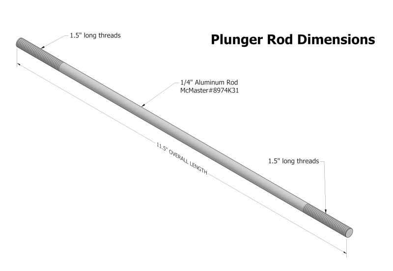
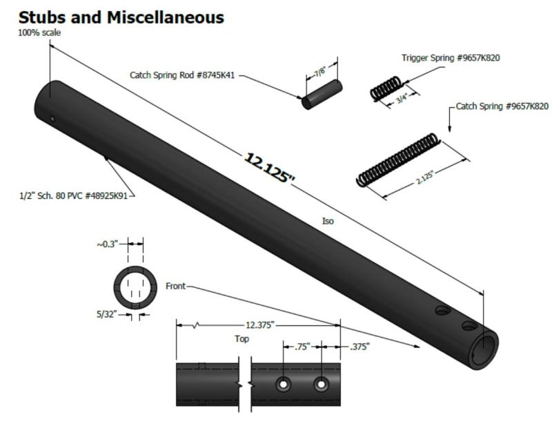
This can be a difficult piece to machine. You'll have to cut the aluminum rod to 11.5", and use a die to cut threads 1.5" long on both sides. During this process you'll have to figure out a way to vise the rod without damaging it. We usually use two pieces of soft wood that you can just crush in the vice. Make sure you don't bend the plunger rod in the process. Both of these will cause major issues later, mostly the plunger rod having tons of unnecessary friction.
We're now using a segement of anodized aluminum instead of the plain stuff. It's three times more expensive, but is much less prone to getting scratched and marred causing the plunger rod to seal like shit. The McMaster# in this drawing is incorrect, and should be #6750K13
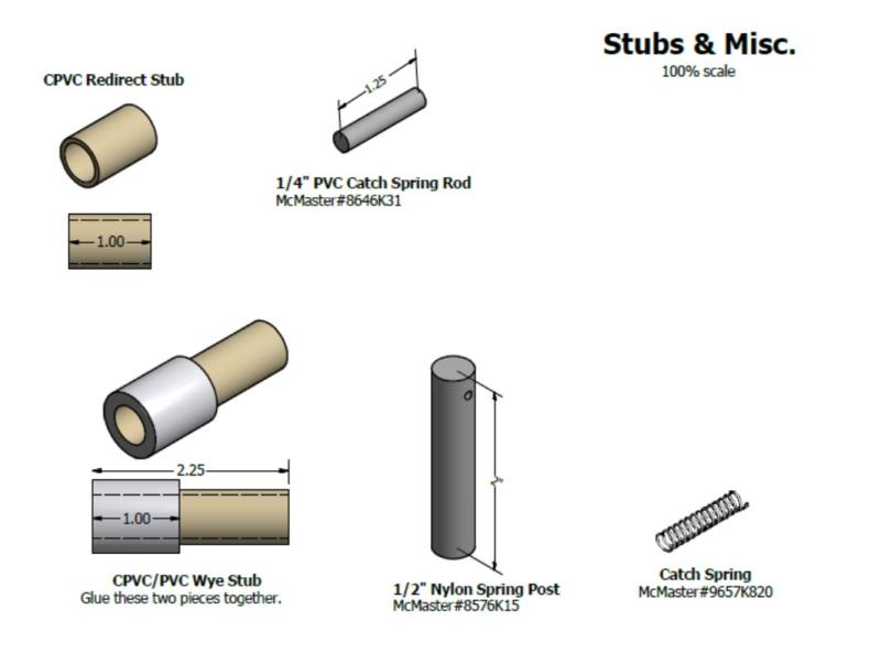
These are just small bits that you'll need later on. #6 clearance hole for the spring post, and roughly .25" away from the top.
Super glue the CPVC/PVC wye stub. You need this to stay together when you press fit the Barrel Assembly together.
Sub-Assemblies
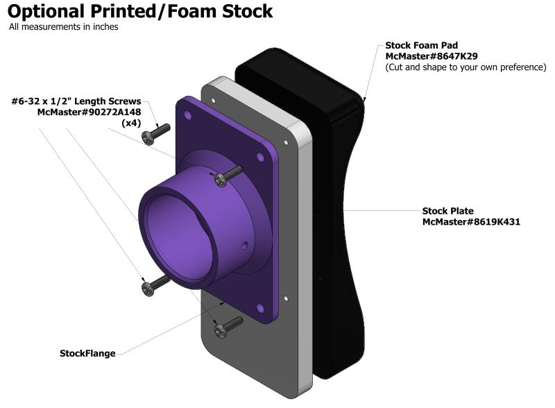
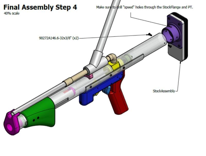
The shape of the foam piece and stock plate are really up to the user's preference. Make sure you drill speed holes after you've put the stock on the plunger tube. Your blaster won't work otherwise. Just use the 5/32" bit and drill 3 or 4 holes through the side of the flange and the plunger tube to allow air to pass through when firing.
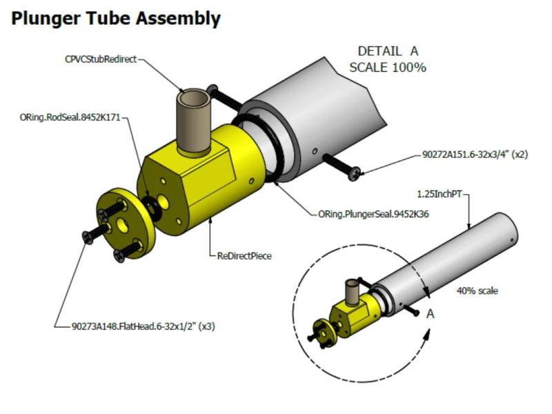
This is the step where you'll need your hot glue gun. Your ReDirectPiece should be loose-ish in the Plunger tube, so add a small line of hot glue around where it's being inserted into the tube. Push that in all the way until the Plunger tube butts up against the top of the ReDirectPiece.
Now take your Redirectpiecewasher, and sandwich the smaller o-ring in between the bottom of it, and the front of the Redirectpiece. It's easier to align the o-ring when you have the plunger rod through it when you assemble. Tighten the screws enough so it seals the o-ring between the two plastic pieces. If you tighten the screws too much, you'll smash the o-ring too much, causing it to have a lot of extra friction on the plunger rod. You'll also want to lube this o-ring up during assembly.
During the Final Assembly, you'll drill the holes you need to secure this assembly to the rest of the blaster. Right now, you should have no holes in the ReDirectPiece, or the Plunger tube.
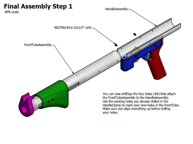
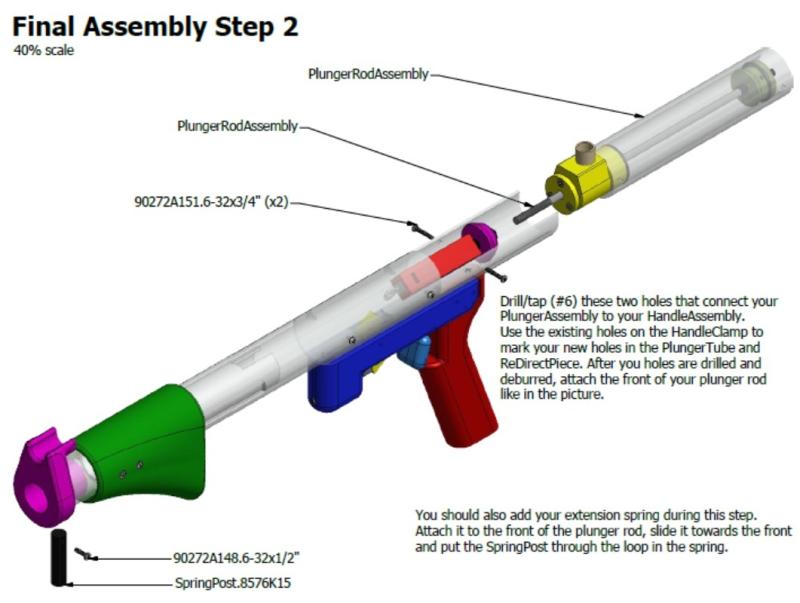
Final Blaster Assembly

Questions, comments, flames, please post...