
Caliburn: Mag-fed Pump-action Springer
#26

Posted 31 October 2016 - 08:12 AM
Co-Owner of the History of Nerf Modding research project, moderator of r/Nerf, owner of BlasterWiki, maker of 3d printed blasters (GitHub/Thingi) and Nerfy art.
#27

Posted 31 October 2016 - 03:12 PM
CAD, template, and partslist files have been added to the first post.
I'm not sure what file types are preferred, but STEP and Solidworks are the only types I can export that maintain multi-part assembly.
Two of the components as-designed have to be made using a lathe. Alternative methods for making the bolt are up to you guys to figure out.
So this can feed/use stock elites right? Also, can it work with, say, banana clips from worker?
It can feed any full-length dart. Stock or knock-off. It will also work with any magazine that fits a stock Nerf Magwell.
#28

Posted 01 November 2016 - 09:59 AM
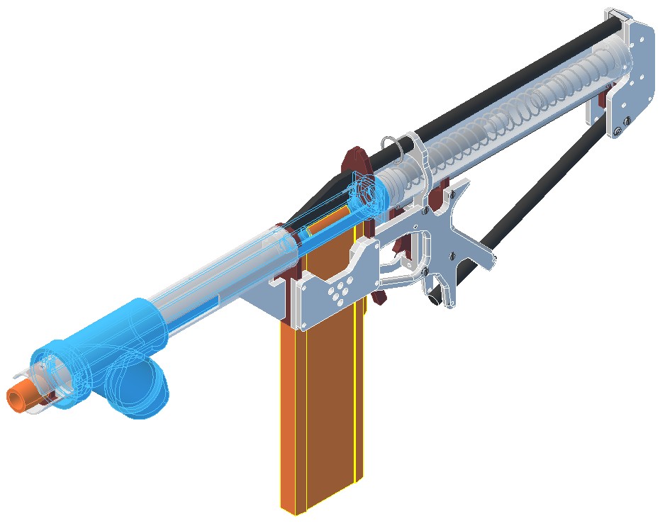
Also, how is the pump attached?
Edited by Silly, 01 November 2016 - 10:03 AM.
Co-Owner of the History of Nerf Modding research project, moderator of r/Nerf, owner of BlasterWiki, maker of 3d printed blasters (GitHub/Thingi) and Nerfy art.
#29

Posted 01 November 2016 - 10:17 AM
I have no experience with trying to make anything that fires Megas, and the only magazine available for those are the Centurion 6-dart. Adapting this to fire those would involve upscaling a third of the components.
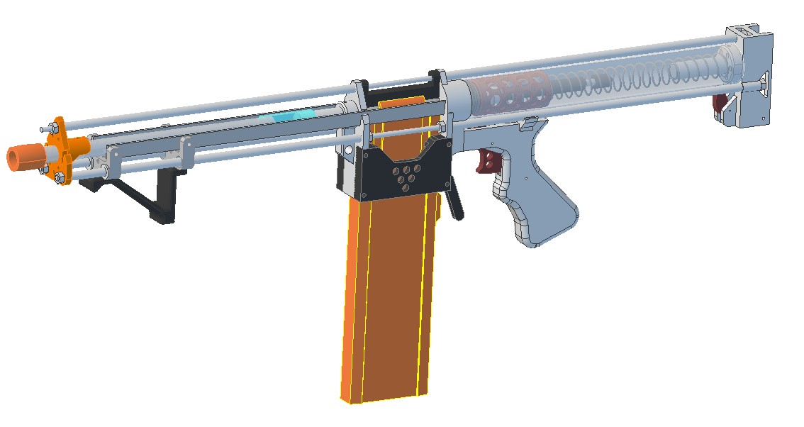
The foregrip attaches to aluminum straps that connect it to the bolt assembly. Here's an outdated render of the design with those parts highlighted.
#30

Posted 01 November 2016 - 07:49 PM
Sorry, what's part#8788K181-CPVC rectangular bar used for?
What materials did you use to make the bolt core? Was it just a solid piece of aluminum or delrin?
-Jwasko, STILL Sole Surviving member of Steel City Nerf and Sober Sister of the Sex Dwarves
We NERF ON all day, and FUCK OFF all night
#31

Posted 02 November 2016 - 11:43 AM
The CPVC is adhered to the "Wiffle Tube" using PVC Cement and put them together in a Vice or C-clamp to cure. You then sand the flash down to the diameter of the "Wiffle Tube" and drill a centered hole.
The bolt core can be made from any scrap rod of aluminum, delrin, or grey PVC. I did not add that material to the parts list. You can alternatively make it out of several pieces of polycarbonate, ABS, or PVC as a sandwich so long as the center hole and OD are concentric on all the parts.
#32

Posted 20 December 2016 - 04:21 PM
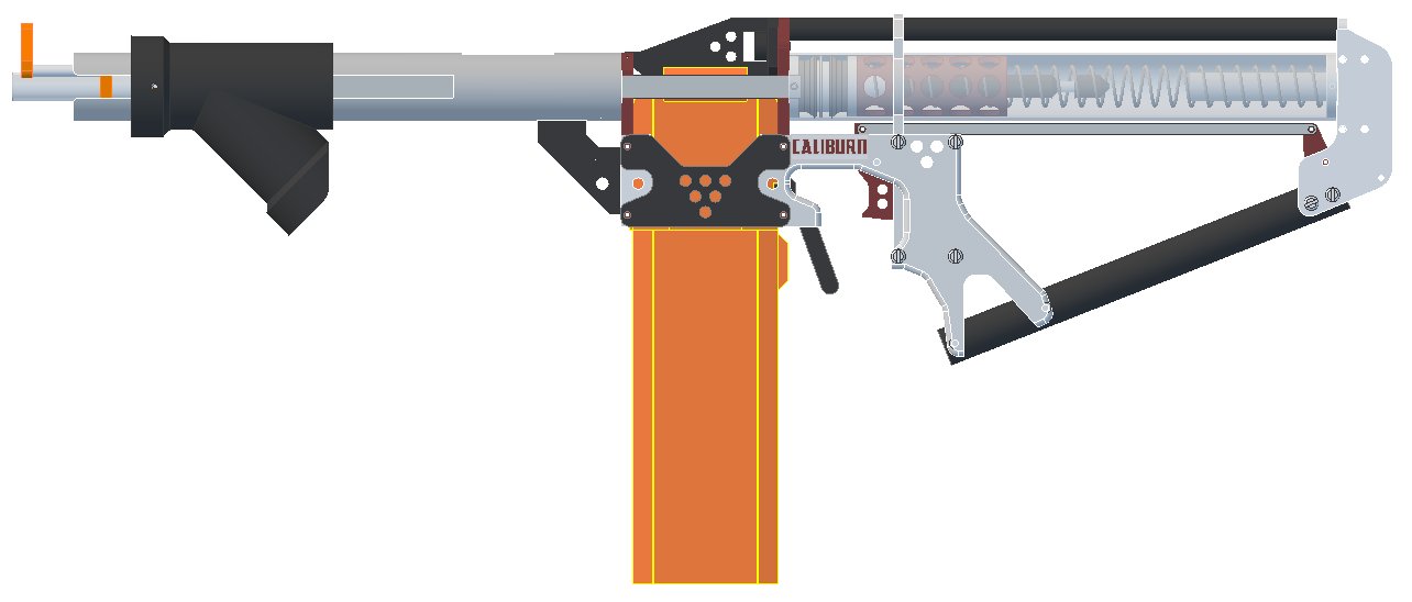
Currently working on a bunch of small revisions to the design. I will be making a couple more of these next month in order to make the construction write-up and wanted to reduce the overall machining time required for each. The lower stock rod is going to be made out of 1/2 NPS Pipe instead of aluminum and there are now NO parts that require internal cuts using a scroll saw.
#33

Posted 15 February 2017 - 05:02 PM

POPULAR
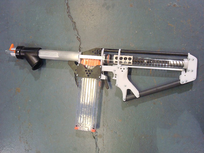
Construction Write-up is done and added to the first post. The Template set and partslist have been updated as well.
http://captainslug.com/caliburn.html
Two of the parts in the write-up are optionally 3d-printed. If you don't have access to a printer those parts are available here.
https://www.shapeway...Y4NG/fgrip-ring
https://www.shapeway...RVQ4Q8DU/frame2
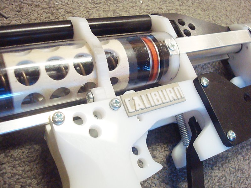
And if you want to add nameplates to your grip panels, here are the ones I'm using.
https://www.shapeway...49LW5/nameplate
I vinyl dye then sand mine to get them to look like this.
#34

Posted 16 February 2017 - 09:55 AM
Gorgeous work as always Slug. How is the clearance between the magwell and the trigger though?
It looks a bit cramped there with the corners of the extended release.
#35

Posted 16 February 2017 - 10:13 AM
The trigger well is roughly the same size as that of a Raider.
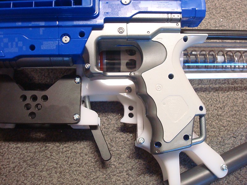
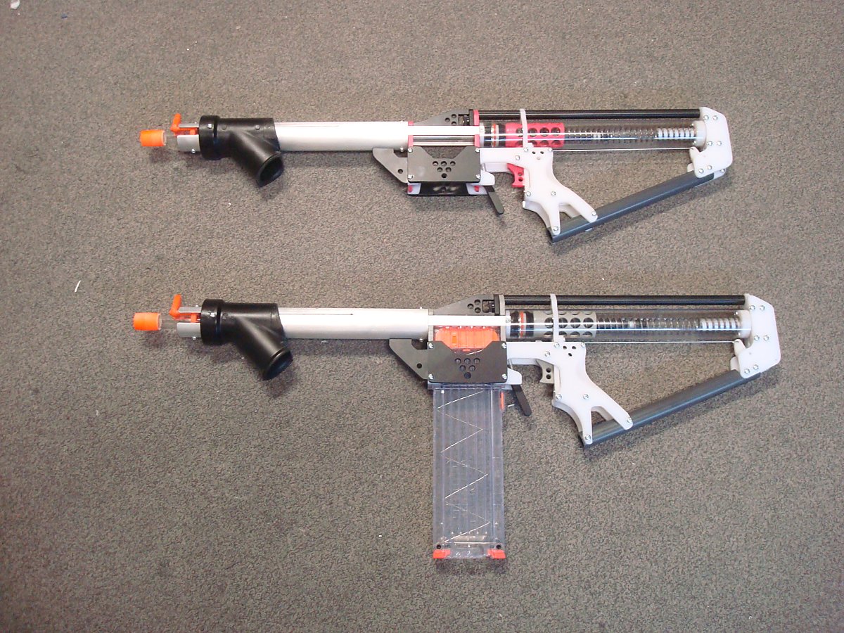
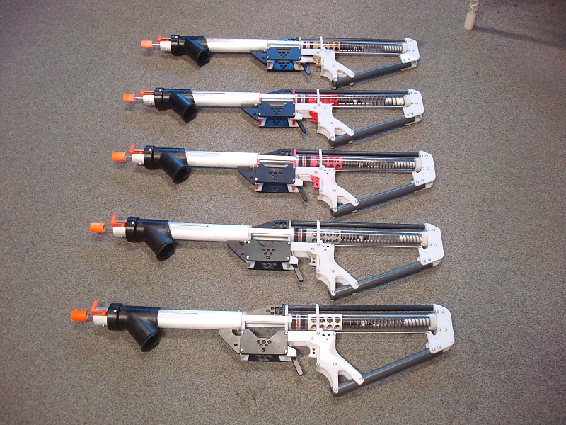
Here are the others I've finished in the past week.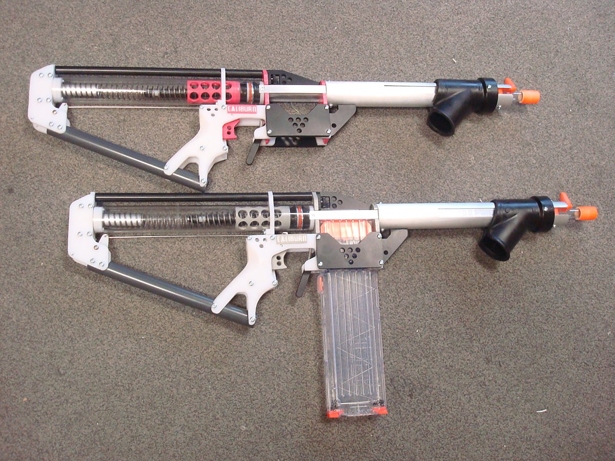
#36

Posted 17 February 2017 - 02:59 PM

POPULAR
Had some downtime at work today. Worked up a 3D-printed version of this design that's held together by 10-32 threaded rods and spacers.
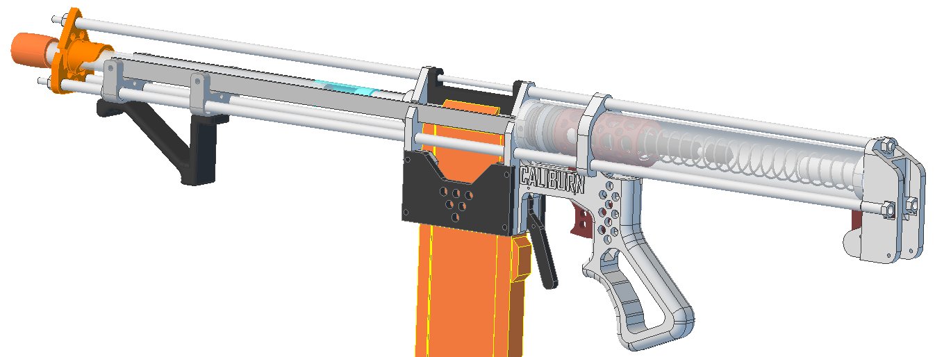
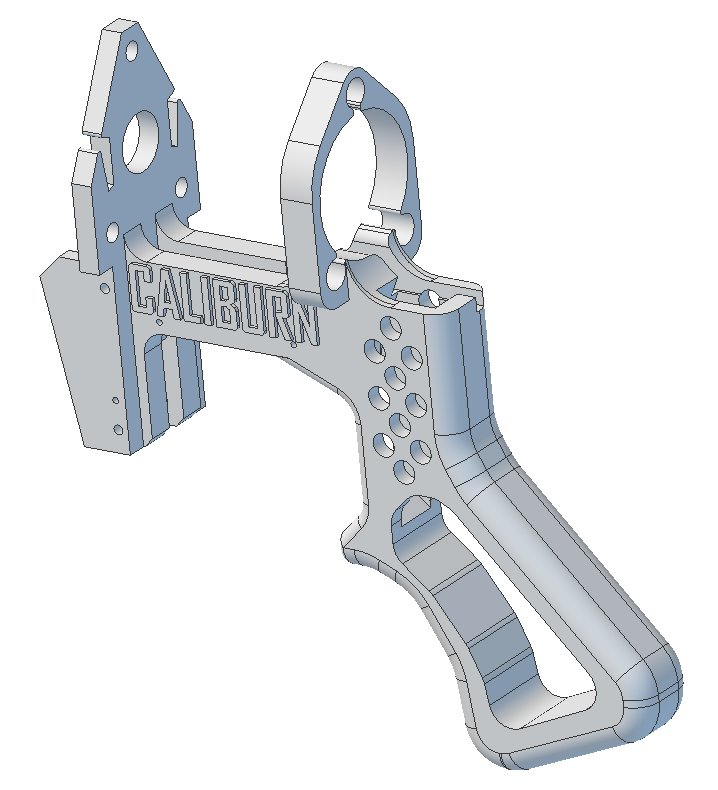
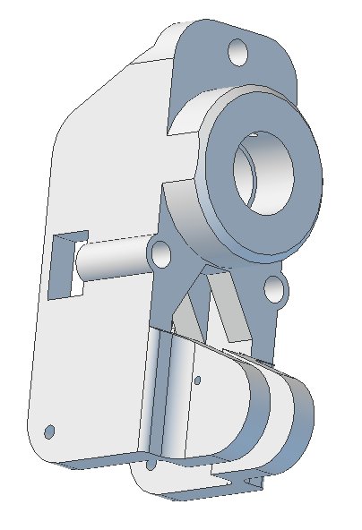
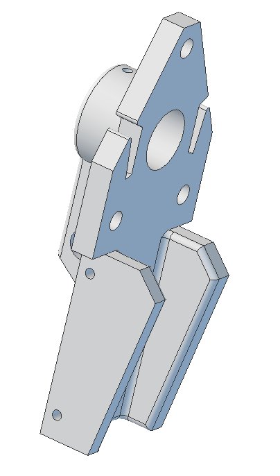
The foregrip slides on the outside of the forward pair of parallel threaded rods (covered by spacers) using some sleeve bearings.
Thoughts?
#37

Posted 17 February 2017 - 03:29 PM
Thoughts?
I would love to see these in printed form.
What material do you suggest this is printed in?
Co-Owner of the History of Nerf Modding research project, moderator of r/Nerf, owner of BlasterWiki, maker of 3d printed blasters (GitHub/Thingi) and Nerfy art.
#38

Posted 17 February 2017 - 03:37 PM
What material do you suggest this is printed in?
ABS, PLA, or Nylon should all work. However Nylon in my experience really needs to be coated in a layer of polyurethane and then sanded if you intend to use it as a handle.
I've left all the parts that have to handle loads really thick and the majority of the structure is tensile load on the threaded rods.
I don't personally have access to a printer at present (and have no intention to ever buy one), but the complexity of this build would really take advantage of the opportunity to consolidate the part count that is afforded by 3D printing.
Someone is going to have to take the lead on printing one of these once I provide the files.
#39

Posted 17 February 2017 - 07:09 PM
I've left all the parts that have to handle loads really thick and the majority of the structure is tensile load on the threaded rods.
I don't personally have access to a printer at present (and have no intention to ever buy one), but the complexity of this build would really take advantage of the opportunity to consolidate the part count that is afforded by 3D printing.
Immediately, I notice how hard that will be to print. You need a large flat area on each part so it can bond to the bed, and from there you want to limit/elminiate overhangs or really fillet/chamfer them out so they've got time to build up before you make the printer do a 'bridge' of filament straight over nothing.
Since I've been so slow on this, PM me your email address and I can shoot you a link to the 360 files I've been working on. In another thread I posted up my trial parts that I have (mostly) printed and tested. I was hoping to get additional feedback from Mechanical Coyote for multiple points of reference, but he doesn't seem to be doing it.
#40

Posted 19 February 2017 - 07:10 PM

POPULAR
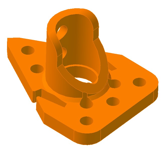
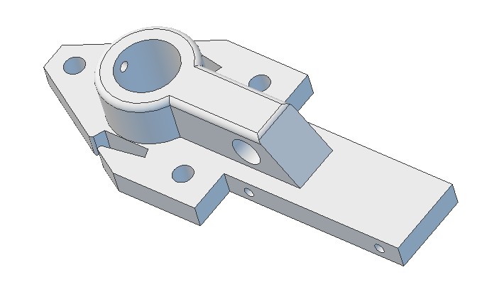
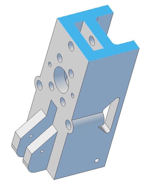
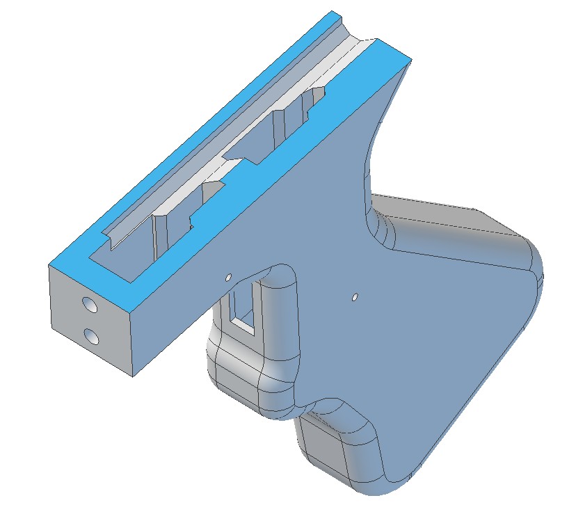
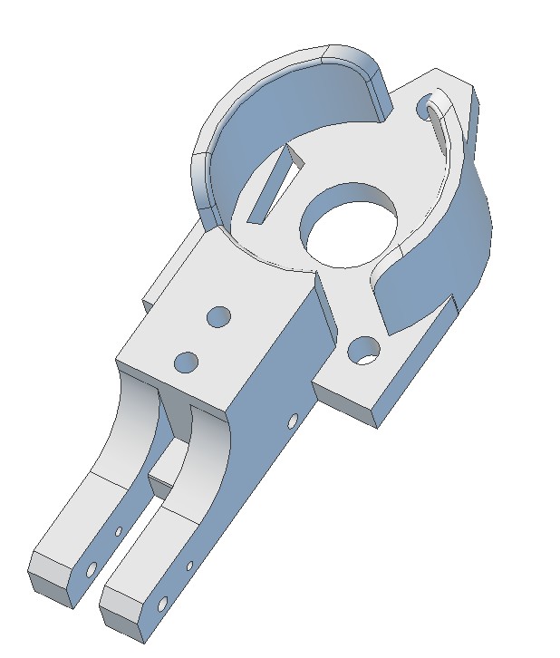
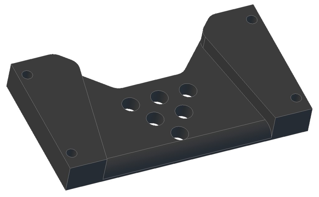
The Grip is split into two primary parts, with the back of the magwell being printed front-side down on the bed, and the grip upside-down on the bed (as is typical). They get bolted together with two screws. A smaller third upper piece can be glued on or wedged in place.
The stock piece similarly gets printed upside-down.
#41

Posted 20 February 2017 - 03:06 PM
Are the foregrip runners 3d printed? They probably could be, but in a beefier configuration. Same goes with the bolt/front seal interface.
I tend to like the first handle (several posts up) with the brackets hugging the plunger tube. Just a preference for overengineering I guess, but am excited for the finalized version.
"sexual innuendo no intendo"
#42

Posted 20 February 2017 - 06:04 PM
Hey Slug,
Any chance you can upload the .dxf files for the flat profiles of parts? The word doc isn't gonna cut it for me- I'm going to try to laser cut one of these out of HDPE sheet.
Contact me for design consultation relating to 3D Printing, CNC Machining, and Laser Cutting. I am always happy to collaborate on viable Open Source projects and/or business ventures.
#43

Posted 20 February 2017 - 08:57 PM
Are the foregrip runners 3d printed? They probably could be, but in a beefier configuration. Same goes with the bolt/front seal interface.
I tend to like the first handle (several posts up) with the brackets hugging the plunger tube. Just a preference for overengineering I guess, but am excited for the finalized version.
Yes. They're .460 thick and both of them attach to the aluminum straps. They could be stiffened further with standoffs.
All of the parts except for the bolt components and except for anything made from tubing or solid rod can be 3D printed on this design. Most of the parts are seeing primarily compression loads since the tensile loads are carried almost entirely by the threaded rods. Any areas seeing tensile loads are oriented to print their layers perpendicular to the expected load. AND they're extra thick where the load is expected.
I'll have a finalized design posted soon.
Hey Slug,
Any chance you can upload the .dxf files for the flat profiles of parts? The word doc isn't gonna cut it for me- I'm going to try to laser cut one of these out of HDPE sheet.
I'll try to remember to add those to the first post tomorrow.
Edit: DXFs added to first post
Edited by CaptainSlug, 21 February 2017 - 09:59 AM.
#44

Posted 21 February 2017 - 06:31 PM
I'm not sure how best to test accuracy to compare stock darts.
Fire at a large stationary target (wall) from a padded rest, compare size of groupings?
#45

Posted 22 February 2017 - 04:01 PM

POPULAR
Meaker VI has been providing a lot of feedback and I think this is as far as it's going to get. The Mag Well is now one part, as is the grip.

#46

Posted 27 February 2017 - 06:16 PM
Amazing work! Now I don't know if I want to laser cut this, or print it... not a bad problem to have. I'm assuming you'll be posting the 3D models of this latest iteration soon? Time to go warm up the Lulzbot...
Contact me for design consultation relating to 3D Printing, CNC Machining, and Laser Cutting. I am always happy to collaborate on viable Open Source projects and/or business ventures.
#47

Posted 27 February 2017 - 06:59 PM
Yes, I'll make those files available after a test print can be checked by someone. PM me if you want to play guinea pig.
#48

Posted 01 March 2017 - 02:04 PM
Meaker pushed me to try the design with Aeromech's PCSR plunger head and catch. And it looks like it makes sense for this and helps to reduce the part count (by 9 parts). The blaster ends up a little bit shorter too.

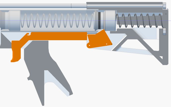
1/8" length trigger pull.
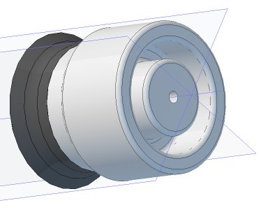
The Plunger head has a ring cut out of the back of it so that it can accept a K25 or K26.
#49

Posted 01 March 2017 - 08:52 PM
Now that's sexy.
What kind of spring is used for the catch itself?
-Jwasko, STILL Sole Surviving member of Steel City Nerf and Sober Sister of the Sex Dwarves
We NERF ON all day, and FUCK OFF all night
#50

Posted 02 March 2017 - 07:41 AM
The same 1" length extension spring I like to use for most things. Retained with trimmed 16ga nails

If anyone would like to provide some feedback on the design, here's the current STEP 214 file.
The plunger tube is now 1-1/4 SCH40 pipe (clear or white) and the rear portion of it that acts as a spring guide is 1 SCH40 pipe.
Edited by CaptainSlug, 04 April 2017 - 02:38 PM.
Also tagged with one or more of these keywords: Mag-Fed, Pump-Action, Springer, Homemade
homemade
Community Forums →
Homemades →
Re-creating the Nerf SledgeFire: The SuperSledgeStarted by Silly, 27 Dec 2021 |
|

|
||
Community Forums →
Homemades →
Clarification of differences between Hoppers, RSCBs, Choppers, and BRIStarted by Silly, 17 May 2021 |
|

|
||
Community Forums →
Homemades →
Project 12: 100% brushless Vortex blasterStarted by snakerbot, 16 Aug 2020 |
|

|
||
Community Forums →
Homemades →
Project 10Started by snakerbot, 05 Jul 2019 |
|

|
||
Community Forums →
Homemades →
Nerf M-1 Garand conceptStarted by Silas4lagoon, 28 Jun 2019 |
|

|
1 user(s) are reading this topic
0 members, 1 guests, 0 anonymous users


