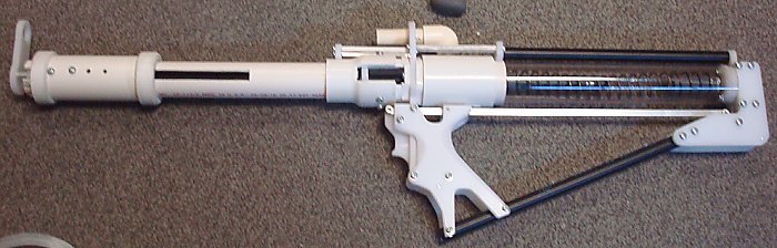
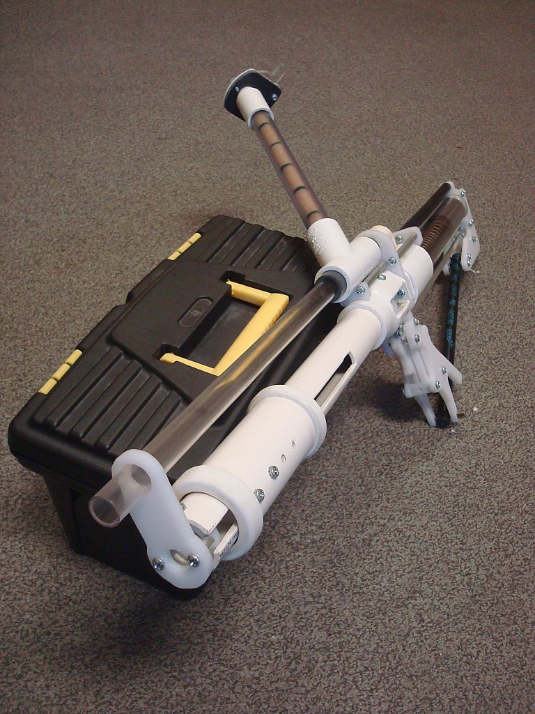
It's completely done, here it is with the spring guide. I will post a new thread once I have a construction write-up done.
But for now, here are the templates and partlist.
PARTSLIST
TEMPLATES
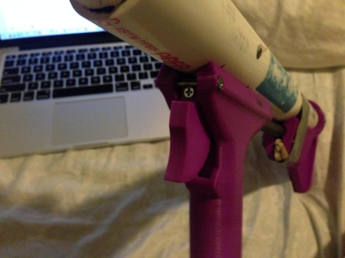
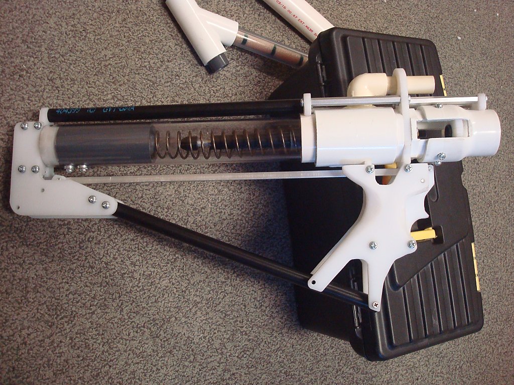
I'm going to be making grips without the upper rest from now on. There's no point in one being there on a platform that doesn't have recoil and they're the source of all of the relative difficulty people are having with sanding their grip panels enough to be comfortable.
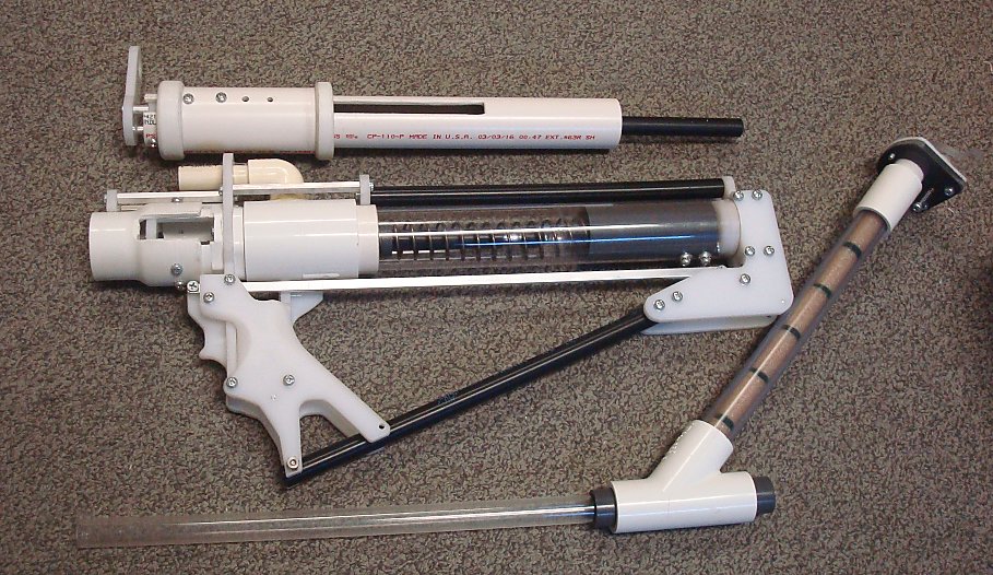
The center of mass is nicely placed just above and behind the grip on this design. The ability to take-down everything without any tools is also pretty nifty. Snakerbot's redirect is working perfectly too.
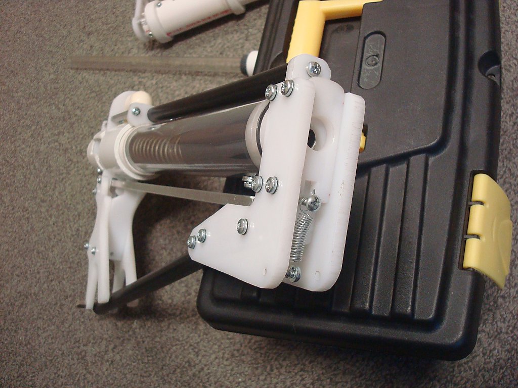
In making this I discovered that my catch plates were much more complicated than they needed to be. A 9/16" through hole works perfectly fine and doesn't required as much travel. It just need to be precisely placed relative to the edge that the trigger linkage pushes on.
The lower stock rod is acting as a tension member against the spring load. So I've switched to just using a long screw and a thumb nut to secure it to the bottom of the grip.
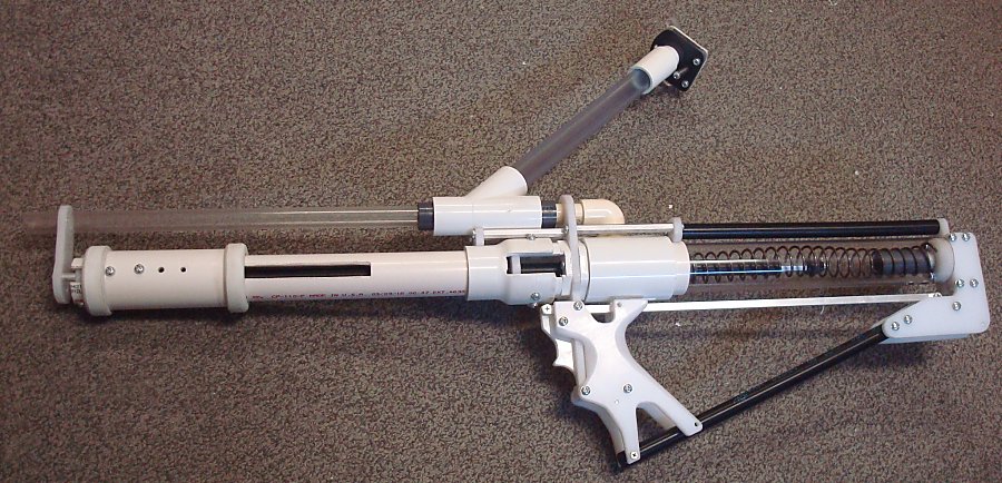
Length tolerances on a few of the parts can be fussy and it took some time to get the pump-grip, plunger, front tube, and so on all interacting perfectly. The pusher rod has to be long enough to push the plunger back, but short enough that it retracts to a position that won't impede the plunger firing. And if it's too short the end of the pusher rod is too close to the redirect seal.
All of these interactions also impact the dimensional requirements for the length of the slots in the front tube, the plates mounted inside the grip, the length of the grip itself, the placement of the catch on the end of the plunger rod, etc.
But with the whole front half of the blaster being so easy to remove, adjusting most of these is a piece of cake.
Edited by CaptainSlug, 24 August 2016 - 03:43 PM.
partlist and templates added
The little critters of nature, they don't know that they're ugly. That's very funny, a fly marrying a bumble bee. I told you I'd shoot, but you didn't believe me. Why didn't you believe me?