Jump to content


Aeromech's Content

There have been 378 items by Aeromech (Search limited from 12-December 96)


By content type

See this member's


Sort by                Order  

#354333 Fix for Omni-directional Plunger Rod Binding/False Catching

Posted by Aeromech on 18 June 2016 - 04:04 AM in Homemades

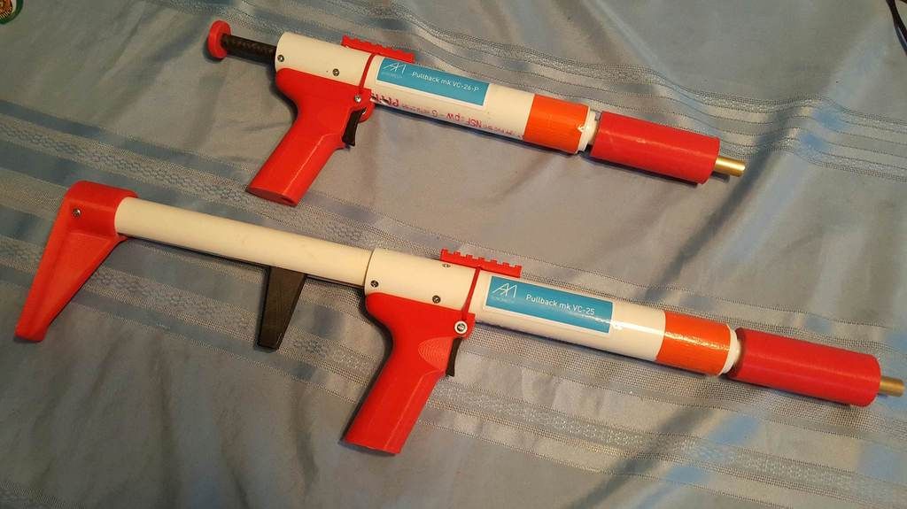
So my distaste for omnidirection plunger rods is not unknown to the nerf community, up til now, they seemed to catch less reliably than unidirectional catches, and were overall more fickle. The problem comes down to spring binding issues, particularly with the [k26], and maybe even the [k25]. As the plunger rod is pulled back and the spring compresses, it does not compress perfectly in line with the plunger rod, and tends to "serpentine", getting all wavy and kinky before it reaches it's final stage of compression. During this time, the spring gets caught in the omni-directional catch part of the plunger rod (with the lower rod diameter) and produces either a VERY unpleasant "crunchy" feeling to the prime, and often results in a "false catch" where the spring actually gets caught in that catch region when you pull the plunger rod back. You think the catch has engaged, and as soon as you begin to let go, and the spring is able to exert it's energy, the plunger assembly flies forward. This leads to swearing, sore fingers, questioning your rainbow catch-making abilities, and an overall hopeless feeling knowing that this lifeless piece of plumbing pipe has defeated you. You're better than that mate. Millions of years of evolution have prepared you for this moment. It's time to take on that omnidirectional plunger and make it yo bitch.


x%20ray%20view%20initial_zpstd3a7nzm.jpg

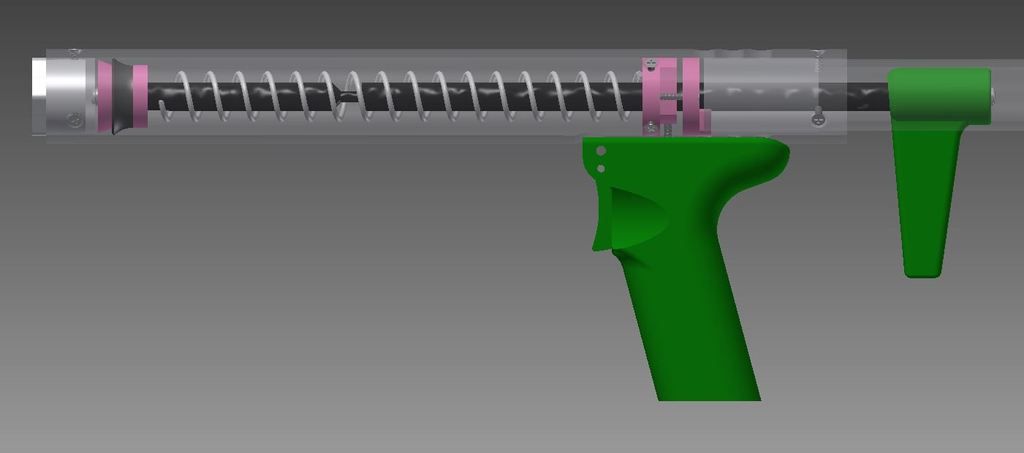
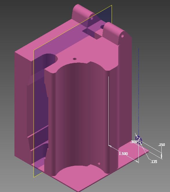
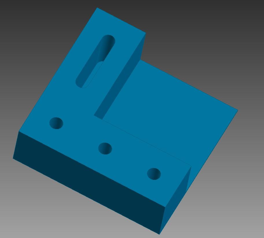
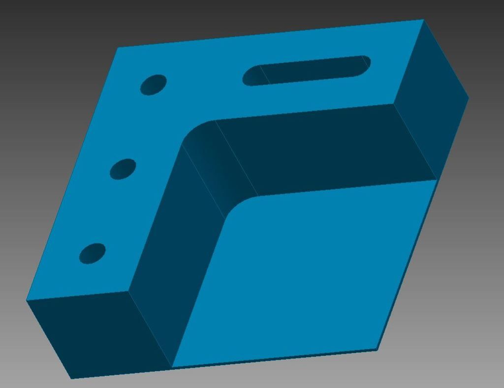
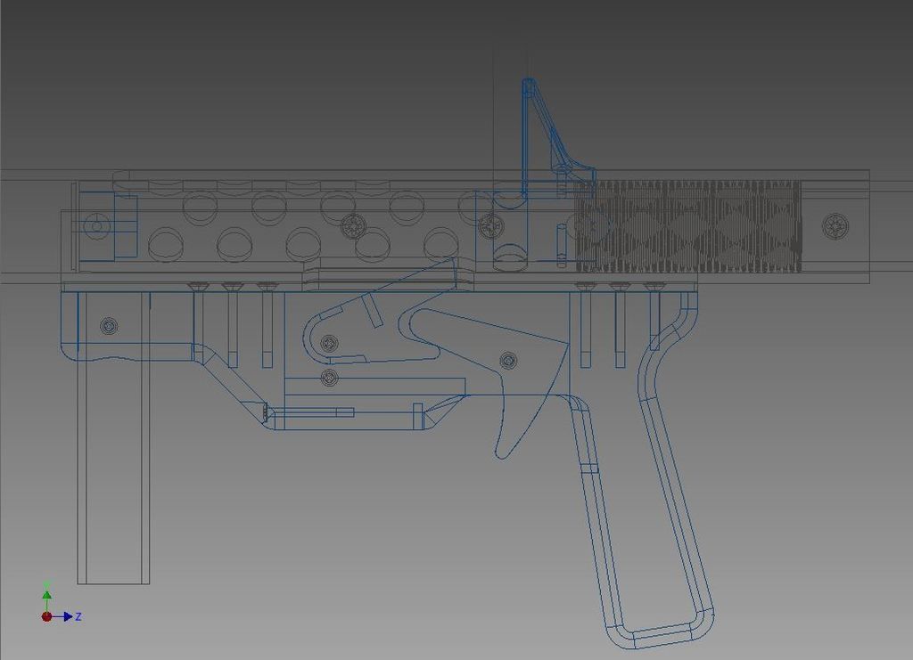
The "Before" photo. Here is a pullback with the main tubes "ghosted" out, so the insides are visible but you can still see the outline of the body tube. Typically, the spring binds in the recess near the front of the plunger rod, where it is supposed to engage in the catch.


1%20inch%20PVC%20piece_zpswsyjxhku.jpg

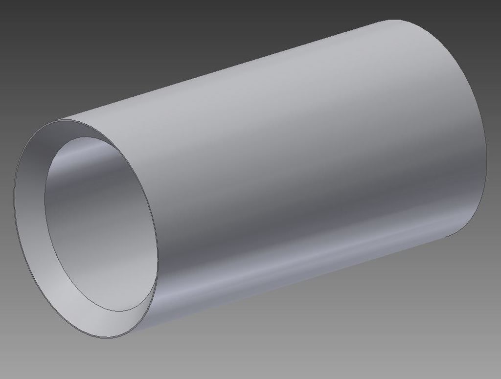
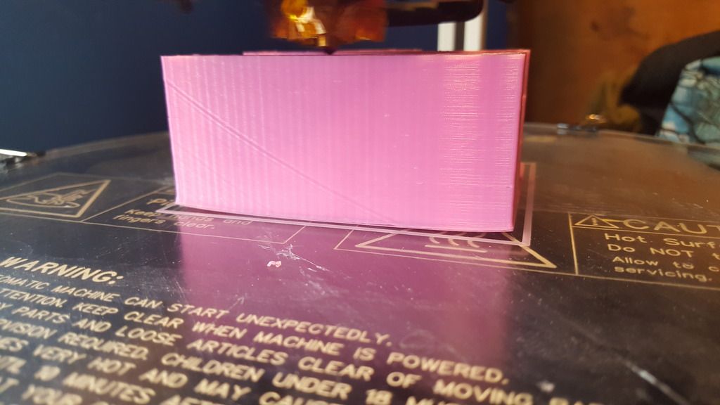
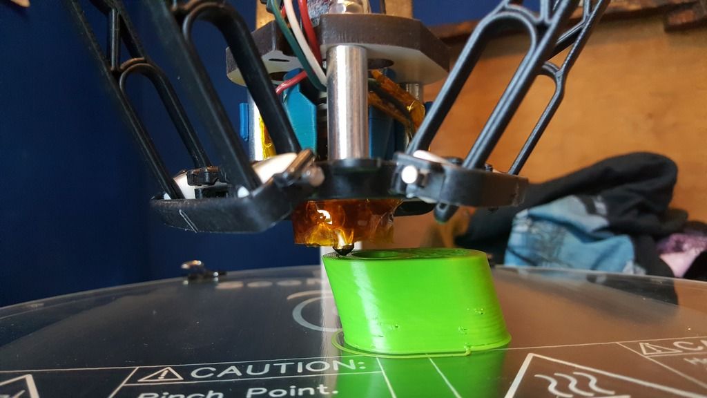
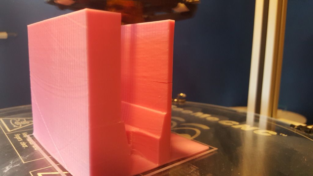
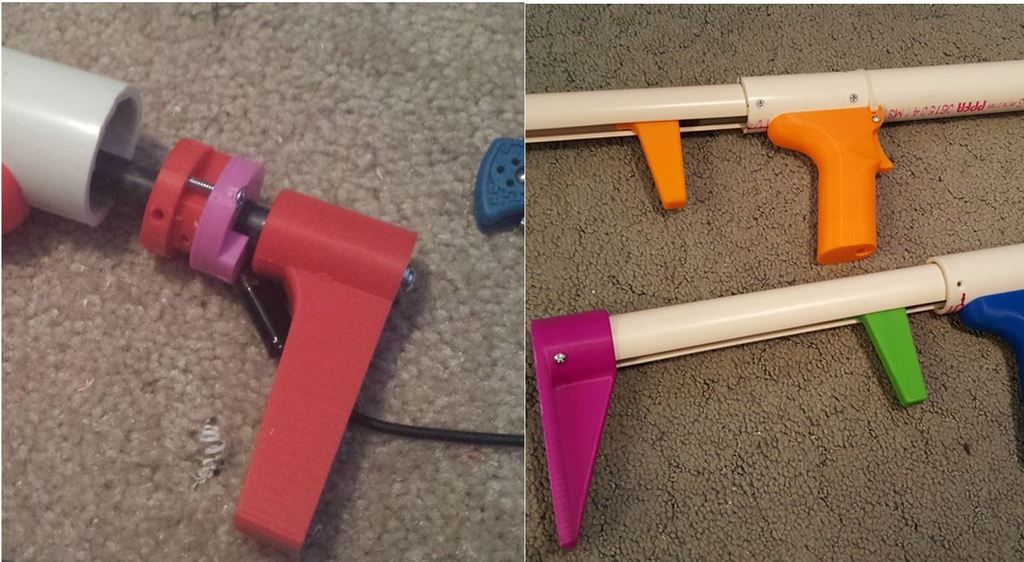
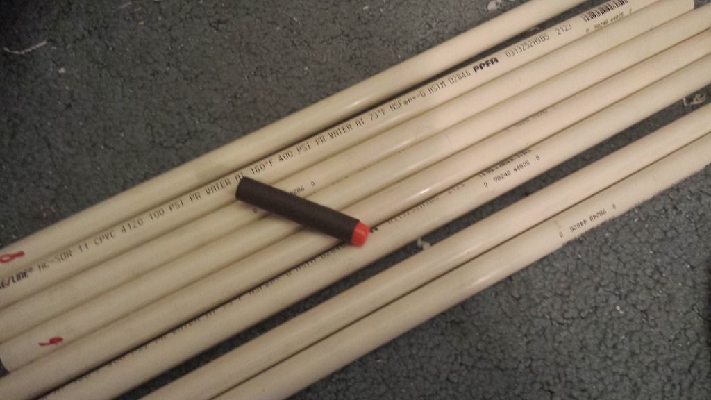
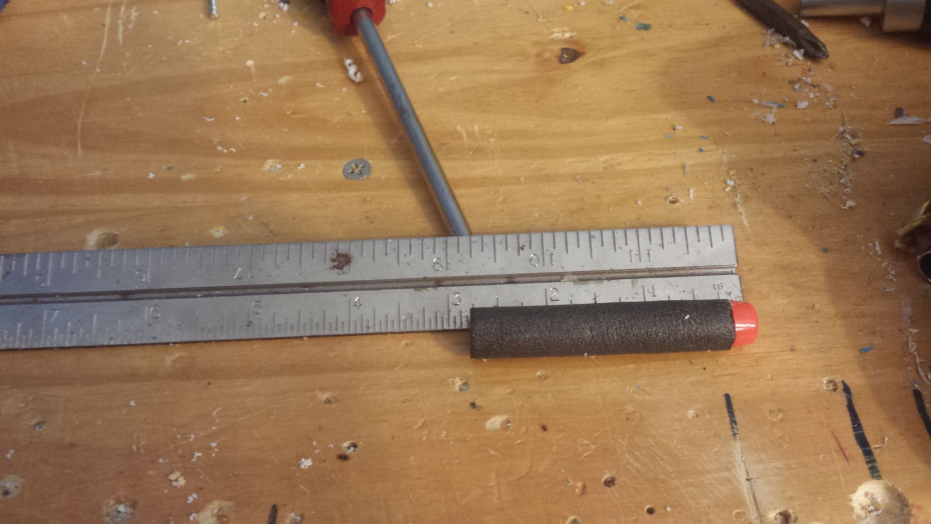
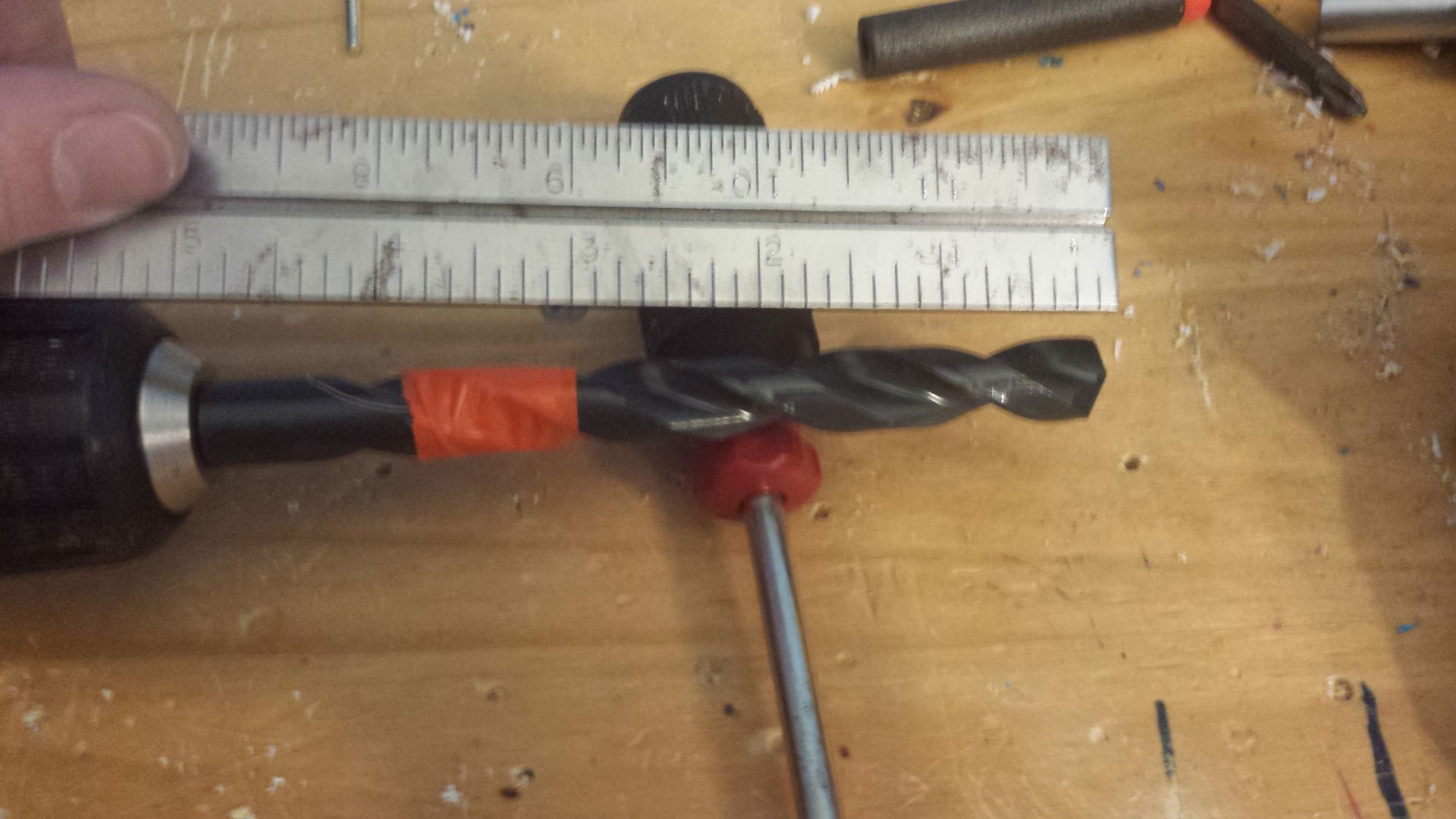
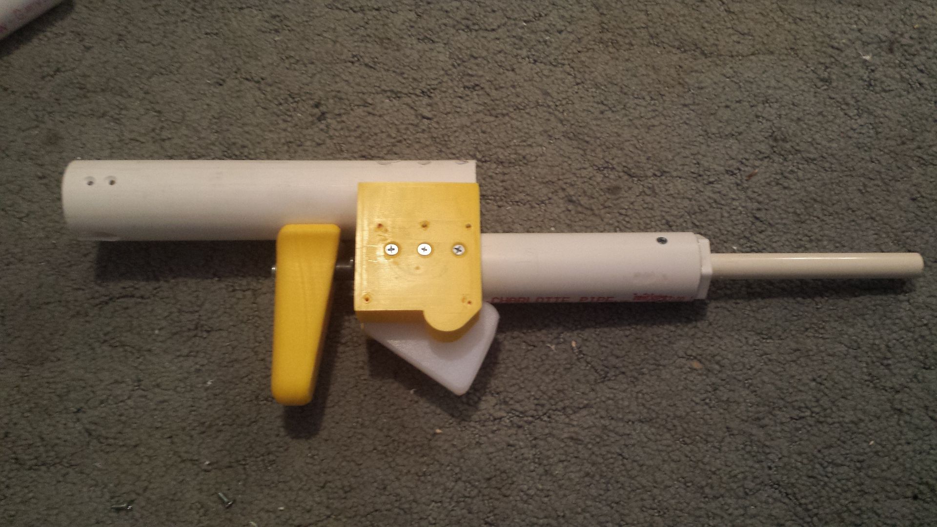
This is it. This is the easiest solution ever. Cut a piece of 1" PVC Pipe, about 2.5 inches. Make sure it is shorter than the spring at full compression, but not too much shorter. Get it close, but make sure it is still shorter. Take note that the front (left side of the photo) of the tube is beveled on the inside. This is important. Put a few wraps of packaging tape around this so it fits fairly snuggly inside the 1-1/4" PVC plunger tube.


internal%20with%20piece_zpsnekatrr8.jpg

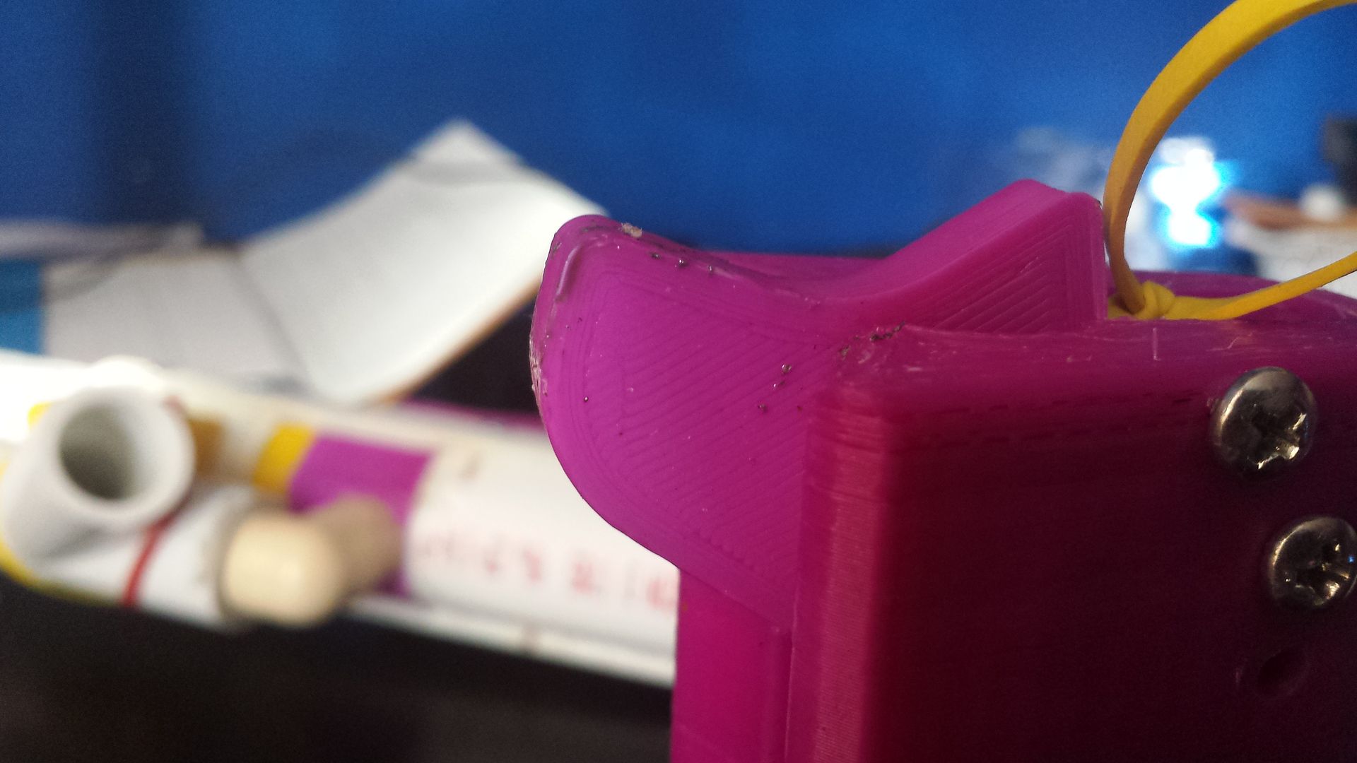
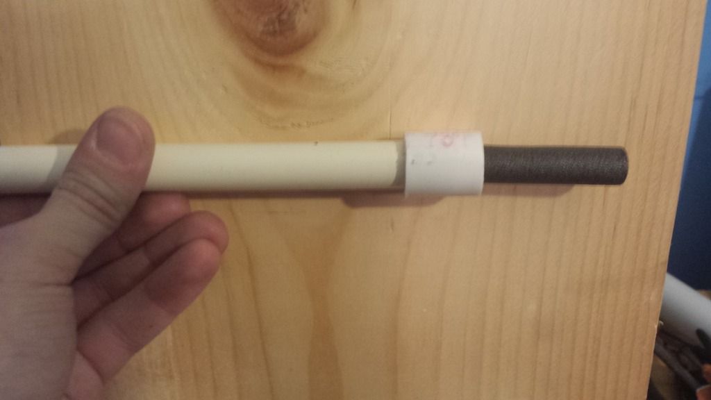
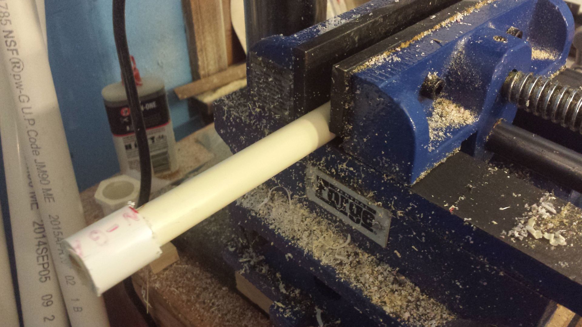
Boom. Throw it in there. Rest this piece against the front of the rainbow catch, with the beveled end facing forward. Sink two screws in there to hold it in place.


internal%20with%20piece%20at%20angle_zps

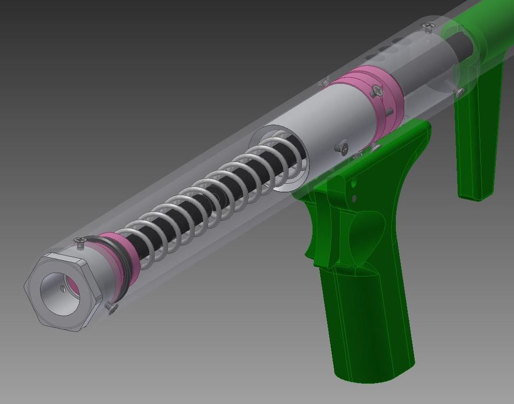
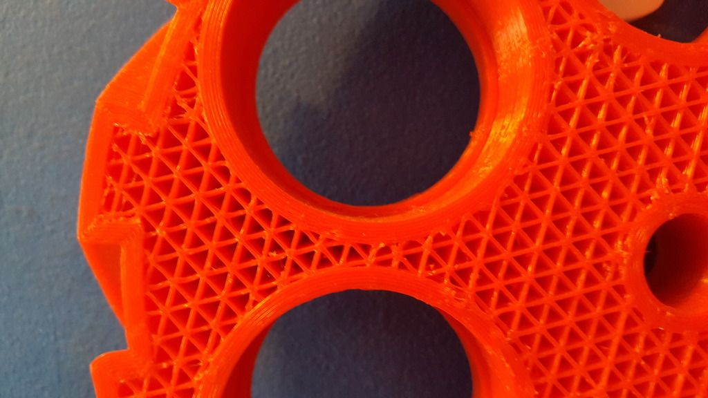
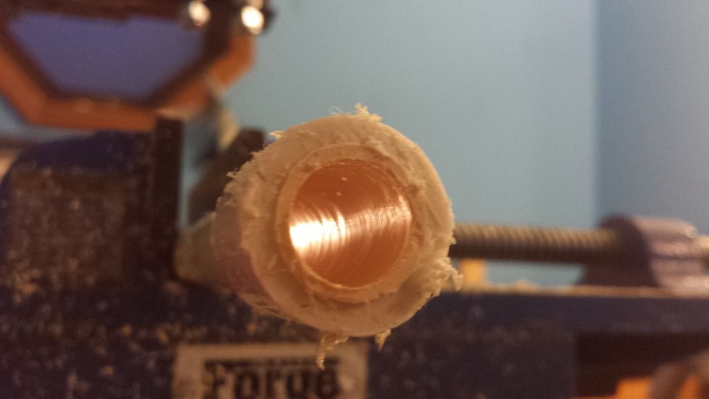
This photo provides a little more insight, the anti-binding pipe goes around the spring. When the spring is compressed, it is "guided" to a more "cocentric" position within the body tube. The bevel smoothly pushes any parts of the spring that may bulge out into position, so the spring cannot bend to the point where it would interfere with the catch region of the plunger tube. After installing this into a rainbow pistol/carbine (5 inches of draw, like 1 to 1.5 inches of precompression, 10 inches of [k26] spring)  all false-catches stopped completely. The prime was smoother, and all the problems I was having with the catch vanished. It caught every time, and smoothly. Follow this guide if you're using a [k26] in conjunction with an omnidirectional plunger rod.


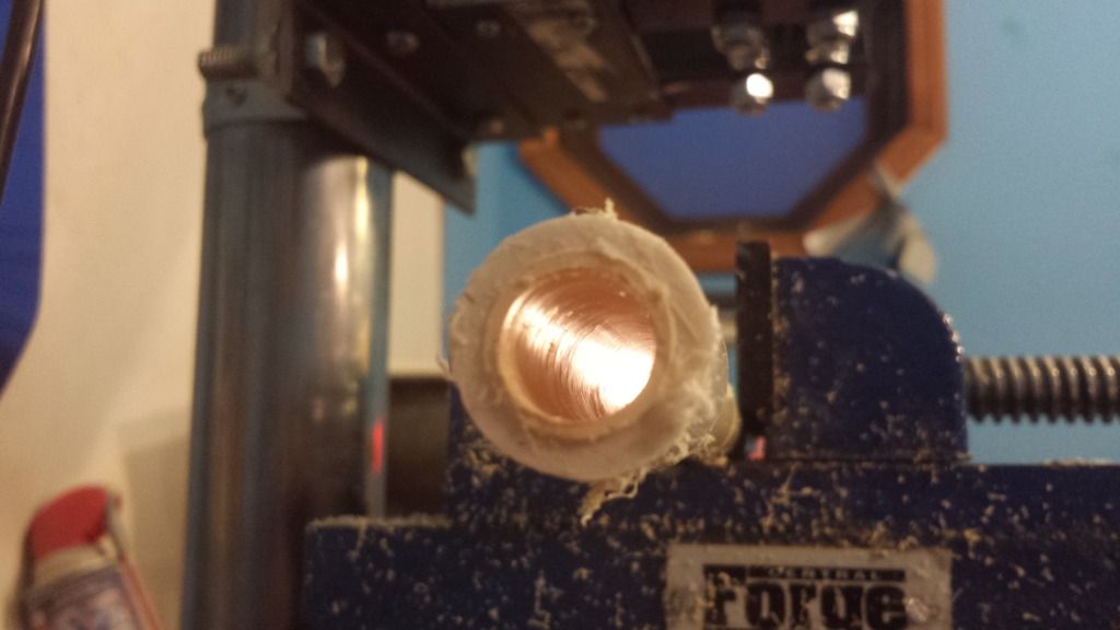
Make sure it doesn't cover up your speed holes (anti vacuum holes). Once you sink in this piece, just re-drill the speed holes in the main body tube through the anti-binding pipe you just installed. Super easy.


#354331 Homemades Picture Thread

Posted by Aeromech on 18 June 2016 - 12:51 AM in Homemades

pullback%20carbines_zpsjfujyg6b.jpg


Pullback Carbines

-5 inches of draw

-10" of [k25] in the carbine, 9.5" of [k26] in the pistol

-Omnidirectional catch on the pistol, with special anti-kinking design on the inside. That's right, no more B.S. false catching and spring binding against the catch rod. This baby catches every time.

-The suppressor looking things are adapters for brass single-barrels

-22 inch overall length on the carbine before barrels/adapters/hoppers


#354314 [CT] Connecticut Nerf Out - Norwalk - Saturday, July 2nd

Posted by Aeromech on 17 June 2016 - 01:06 PM in Nerf Wars

Yeah let's go


#354265 Midsummer Mech-Out 7.16.16

Posted by Aeromech on 16 June 2016 - 02:46 PM in Nerf Wars

If you're coming from Manhattan or Queens, we should arrange a carpool or Uber. This looks obnoxious to reach via public transit.


Good idea. If you can make it to one of the train stations closeby, an Uber or something wouldn't be too bad. Or hell if worse comes to worse we can have a pickup before the war.


#354139 PCSR: A new homemade design

Posted by Aeromech on 12 June 2016 - 09:36 AM in Homemades

Yup! It was in the google drive document called "build notes" in the PSCR folder. But for those wondering, the McMaster rod seal component is 9505K79. This is the only part that you would not have on hand should you be familiar with rainbow builds.


#354018 Definitive Guide to 3D Printing

Posted by Aeromech on 06 June 2016 - 11:58 PM in Homemades

Speaking of beds, I bought the glass plate and am using blue painter's tape. I tried hairspray and didn't get results, so it was one of the many variables I changed all at once. The blue tape works great, but my problem could have been bed leveling. That stuff is super critical - get a sheet of regular printer paper (typically 20# bond) and move your nozzle various places over the paper over the bed. You should need to tug the paper a bit to get it to move from under the nozzle, but the nozzle shouldn't tear the paper or scratch the plate. It should probably dent/scratch the paper. If you're using tape, put that under the paper too.


Before I set my printer up that way, parts would come loose pretty easily and sometimes during the print. After I set my printer up that way it requires tremendous force to remove a part and my parts now have very flat, smooth, blue undersides.

I tried blue tape before, problem there is that the tape itself would peel off the bed from the force of the ABS. Glue stick glue seems to work best for me, the best thing is to keep the damn print environment hot if you're working with ABS, again easier said than done. I'll have to try PLA I guess, maybe get a spare nozzle so I don't mix filaments.


As you said, 3D print layers aren't chemically bonded. Could doing a sort of... Rubbing i guess? help with creating one? Like, taking a paintbrush with solvent weld on it and brushing it on the outside of the print to bond layers.

Short answer is no. The problem is anything that could penetrate between layers and lines of filament would melt the damn thing. Put acetone on the end of a Q-tip and touch it to a part. It will become a rubbery consistency and lose all it's accuracy. Once upon a time I tried to do this to experiment with post print repairs, but it really doesn't work, so that's why I reccommend using some super glue for parts repairs


I've heard of methods where you boil solvents under the part which smooths out the surface finish a bit. Two problems here; firstly it really is only a surface finish and there is no way to really effectively penetrate it that I know of. Plus I don't even think that you would WANT to penetrate too deep because the infill would be dissolved. Hmm, maybe I should add a section for terminology too tomorrow.


The second problem is that doing this vapor post treatment is incredibly fucking toxic. I've never died before, but I imagine it isn't pleasant, so I don't fuck with that shit. TL;DR keep your print environment warm and free of wind or drafts.


#353992 2016 Nerf War Schedule

Posted by Aeromech on 05 June 2016 - 07:33 PM in Nerf Wars

July:

16th [NY] Midsummer Mech-Out


#353991 Midsummer Mech-Out 7.16.16

Posted by Aeromech on 05 June 2016 - 07:21 PM in Nerf Wars

Mech%20out_zps50x2jebz.jpg


Hello once again, friends!


The time as come for yet another summer of nerfing. I'm glad to have hosted some successful winter events so far, and I am proud to present my first summer war! Get acclimated to the climate of the hot and humid Northeast before the coming Apocalypse here on Long Island.


Where & When
Eisenhower Park
East Meadow, New York 11554
July 16th, 2016
From 10AM to 5PM


Precise Coordinates: Field 2 of Eisenhower Park, Here's the GPS link: 40.725879, -73.568206


Rough Directions: The closest address to the entrance is 1899 Hempstead Turnpike, East Meadow, NY 11554. Plug that into your GPS and it will take you to the intersection of Hempstead Turnpike and Park Blvd, the main entrance of the Park. Turn onto Park Blvd. If you are taking the LIRR, look to get to the Hicksville Station from Penn Station.


NOTE: I am looking into this park and other lower-profile parks as well and seeing if I can book areas out so we can have exclusive access. I will keep you posted here and on the facebooks.

Weather

Here's the linkeroo --> http://www.weather.c...ay/l/11756:4:US


Rules
- Must be 13 or older to participate
- EYE PROTECTION IS MANDATORY.
- Absolutely no shooting, pointing blasters at non-players. I will personally escort you out if this rule is broken.
- Be respectful of players and non-players alike. If we need to move, we move.
- No facemasks, camo, or super tactical clothing.
- You WILL dart sweep

- If you are being a jerk/whiner you will be asked to leave. Never had this problem before, let's not start now


What to Bring
-EYE PROTECTION: There's a home depot literally across the street. If you forget it, cough up the $5 and get a pair there.
-Hot weather amenities: A big bottle of water or gatorade, a snack, a towel, sunscreen, maybe a hat.
-At least two primary blasters.
-$5 or so for pizza. May end up getting Domino's pizza. It's sacrilegious for Long Island, but it's cheap.
-Extra Darts.200 is my minimum that I like to carry.


Blasters and Foam Darts
-ABSOLUTELY NO BLACK OR CAMO PAINTED BLASTERS
-No homemade compressed air powered blasters. All other homemade spring powered blasters, and modified or stock store-bought blasters are sweet. Bring extra homemades if you got 'em, expect to be pelted with high energy homemade foam blasters should you attend.
-#6 washer weighed slugs ONLY for homemades. All other nonmetal darts are allowed. No slingshot weighted darts, no exposed metal darts, no glue-dome darts. This is your only warning.

-Bring extra blasters that you are OK with others using. We need as many extra as we can get.


Game Types
-3-15 and 5-0 Team Deathmatch
-Wingman Deathmatch
-Bomberman: A game of my own design; this time with better equipment! [think Luke Skywalker firing proton torpedoes into the Deathstar]
-2 or 3 way Defend the Core
-Super Secret Objective Based Round?!


Food, Downtime, and All Other Rules

We are going to keep rounds moving quickly this time around, with pizza and cold drinks being delivered from Domino's at a pre-determined time, probably around 1PM. Last winter, rounds were a little slower than I would've liked, so this time we'll keep things rocking and then have a solid hour for lunchtime midday.


It's gonna be hot. I will have a cooler of stuff and soda will be brought with the pizza. No alcoholic beverages, please, if you want to get some beers afterwards that's fine, but not while we are playing.


The don't be a douchebag rule, as always, is in effect.


PARENTS OF YOUNGER PERSONS: You are always welcome to play with us, just keep in mind typical participants range from 13 all the way up to ladies and gentlemen in their 40s. We are not a day camp, we are not a nursery. We are under the impression that all participants will act in a mature manner. There is no adult supervision, no liability insurance, and no one who will take responsibility for your child. While injury is unlikely at best, this is an intense sport just like lacrosse or hockey.


Attendees: If we get 20 or more that show up, I'll raffle off a free rainbow pistol

RSVP Here, or on the book of faces.

Aeromech

Jesse

Errol

Van

Devil + like 2

Jboynerf

Watch out for DX

Zack the mack

Nerfgeek

Alphatrooper


#353989 East Coast Geddon Warmup War - June 4th in North Brunswick NJ

Posted by Aeromech on 05 June 2016 - 06:58 PM in Nerf Wars

Looks awesome from the footage. Real sorry I couldn't make it to this one.


#353988 The STAN gun

Posted by Aeromech on 05 June 2016 - 06:00 PM in Homemades

Saw the attachment on one of your blasters at plains. I can say from experience that this setup is shockingly effective as suppressing fire.


#353985 Definitive Guide to 3D Printing

Posted by Aeromech on 05 June 2016 - 02:41 PM in Homemades

FOREWARD

This guide is in response to the several emails per month I receive about 3D printing, and it is easier to throw everything out there once than having to regurgitate the same information a dozen times to as many different souls. People unfamiliar with the art seem to forget that it’s not magic, and it’s not the end all answer to your homemade nerfy engineering problems, so whether you are on the fence about getting your first printer, have some ideas about a new groundbreaking 3D printed blaster, or have your own printer and need some advice in parts design or printer settings, here is a condensed summary of all my experiences to get you started. Please keep in mind the information presented here is nothing new, you can google most of this yourself and find similar results, I've never been able to find a single source with all the information I present here; I am no expert, but I do print a lot and have found a nice set of guidelines I like to follow. So think of this more like a noob’s guide to 3D printing. Chime in with your experiences too, everyone’s mileage is a little different.


magreciever_zpsdfoynddj.jpg


1. BEFORE YOU BUY

1.1 Things to Consider

Think about your hobbies outside of nerf, how often you will realistically use your new toy, and what other applications you will (read WILL, not COULD) use the printer on. The printed products are often unsightly in their monotone colors; they will not impress your non-techy significant-other and are not really suited for furniture grade applications, however, I have printed cupboard hinges, light fixtures, and small statues with mine, and myriad other non-stress-critical applications are good places to use a printer in your everyday life.


1.2 Types of Printers and their Specifications

These consumer requirements that you have identified will lay the foundations for the specifications of your printer, most notably, the size. There are two figures to keep in mind here. Firstly, the printer dimensions. Self-explanatory, the physical space the printer will occupy on your desk, table, workbench, etc. The second is the print volume. This one is a little bit trickier and will vary based on the type of printer. “Delta” configured Printers will have a print volume that is shaped like a cylinder, and the print bed will be shaped like a circle. Most other types of traditional 3D printers, sometimes called “gantry” or “X-Y” printers will have a print volume that is box-shaped, with a rectangular shaped print bed.


1.3 Types of Printer Filament, the “Ink” to your printer

The two main types of print materials are ABS and PLA, sold as rolls of filament. Basically the “ink” to your printer, and each type has its’ own benefits and drawbacks. I print exclusively in ABS, mainly because of the relatively low melting point of PLA, and I am wary of the spooky materials sciences surrounding plastics as they approach glass transition temperatures. PLA transition temps is 70-80 °C, where ABS is 220-240°C. Read: you are probably fine with PLA, but I just prefer to be on the safe side of things, coming from a region of hot, humid summers. So this guide will focus mostly on printing with ABS.


This being said, ABS is a pain to keep under control. It likes to be kept very hot and requires the use of a heated bed and adhesive to keep it stuck down while printing, seen below. Most materials, thermoplastics in particular, like to shrink when they cool down. Essentially, as the top layer of ABS cools on top of a layer that is already hardened, the top cooling layer acts like a flexing muscle, and as it shrinks, pulls up the layer underneath it. This phenomena leads to “curling” of the ABS, causing the edges of a printed part to peel off of your hot bed, and may cause delamination between layers, i.e. the separation of the layers mid-print. No bueno for stresses. We’ll get into the engineering a little later. Additionally, ABS carries more odor with it than PLA. Not necessary a bad odor, but one that you’ll have to get used to should you print in an office or something. Below, you can see the ABS on my part curling up from the bed. The glue was 2 weeks old and I forgot to wash and reapply the glue properly. Luckily, this is only a prototype part and it's not going to be going on any blasters long-term.


IMG_20160605_153438_zpst6leye7x.jpg


For PLA, a hot bed is not absolutely necessary (but still recommended), and because of its’ low melting temperature, is less likely to curl up on you, and produces less odor than ABS, but I’ve heard it is more likely to jam up in your printer, so maybe a little bit more of a maintenance hog. It is also more environmentally friendly than ABS, as it is made from plant based oils. I have far less experience with PLA, so someone else that uses it is free to chime in.


1.4 The Shit Nobody Talks About

There are so many drawbacks and inconveniences to 3D printers, and I will mention a few here and go into depth several of them in this novella. For one, TIME! I am printing a receiver for Nerf magazines for a PCSR variant, I’m only making it as a prototype, yet this 4 x 4 x 3 part is going to take 12 hours to print and it’s only a prototype part 4 layers thick! Damn, there is almost always a better way to do things than 3D printing unless your geometry is incredibly complex.


SMELL! ABS smells up your room. SOUND! I need headphones/earplugs to be able to sleep at night any more if I make any overnight prints. TEMPERATURE! If your print room is cooler than like 80 degrees, your prints will tend to delaminate and peel off the bed. TROUBLESHOOTING! DIY printers means DIY fixing. If parts break, you have to take the initiative and reverse engineer some of the parts/ go back into the manual and figure out what’s wrong. This experience was a crash course in electronics, mechanics, and stress application. Luckily the Rostock has a great instruction manual. LIGHT! If printing at night, the display is backlit and I have yet to modify my code to turn it off. SAFETY! We’ll get to that in a minute.


1.5 Pricing

All of these factors, maximum temperatures of the hot-end, type of printer, size of printer, the inclusion of a heated bed, will all affect the cost of your printer. I have seen some for as cheap as $200. Some are as expensive as $3000 for consumer models. Some are pre-built, other have some assembly required or come as kits, and hell, if you are good enough you can literally build your own from zero (Read: You probably aren’t good enough to build your own from zero.) I chose the Rostock Max V2, a kit-build, with everything included in the box, just nothing put together. The wiring, mechanical assembly, soldering, tuning, and troubleshooting, and troubleshooting, and troubleshooting was all left to me. If you want a fun project, and are confident in your building/tinkering skills, I say go for it. If you just want to get printing already and can’t be bothered with the VERY likely screw-ups of DIY, then a pre-built one might be the way to go. Market price for my printer is $1,000 for the kit, but because I put it together myself, I have the print volume of a printer twice as expensive.


Being builders of homemade blasters, most of us reading this are probably very mechanically minded individuals. If electronics and software aren’t your thing, I’d say don’t worry too much. If you have a kit build, read through the instructions and jot down any questions you have, find community resources, reach out to the company, google how to make proper connections, etc. I had no problems with my Rostock instructions, they were very thorough. As for software, it is my understanding that most kit builds operate on software that can be downloaded from a community site. For my printer, I didn’t write a single line of code! It was downloaded from an open source webpage for 3D printers.  This will probably be the case with almost any other kit or pre-built printer you come across.


One last thing to consider is the community of people surrounding your printer. Is the company reliable and trustworthy? What do the reviews say about this printer? Are experiences generally positive? What do these guys use theirs for? Feel out the market for something you like.


It’s all very specific to each person and is a decision that is ultimately your own to make. This is where I cannot help you. Research the shit out of printers and find one that you like. Hell, go on craigslist and see if you can get a used one for cheap. Fixing a broken printer or building it from a kit really gives you an idea of the things’ personality. It’s hard to explain. But it feels right.


2. THE GOOD STUFF

2.1 Terminology

I guess now would be a good time to introduce some of the common vernacular we use round these parts, if things weren't technical enough for you yet.


Below is a half-finished part that I hang on my wall to demonstrate some of the physical phenomena of 3D printing. I have referred to "layers thick" a few times already, and this is precisely what I am referring to, more correctly called "perimeters". Generally, the more perimeters you have around the outside of your part, the sturdier it will be. You can actually count the number of perimeters I have here, This one is 6 layers/perimeters thick. When I say "layers thick" this is what I mean, as opposed to "layers tall" or how many individual, horizontal layers make up your part (the number of cards stacked up in your deck).


The second quality to note is all the cross hatching hexitriangular nonsense you see in between the perimeters. This is called "infill" and basically allows for the print to be completed faster than if it was a completely solid part, and still keep the finished product relatively strong and lightweight. The infill basically forms many little "tubes" that follow the layers vertically upward, the view you see below is a "top" view, so the print bed was originally on the underside of this part. Not much to say here, except I like to keep my infill about 40%. This means 40% of the inside volume is occupied by the infill filament, and the remaining 60% is air. You can go anywhere from 0 to 100% infill, but at some point diminishing returns kicks in, and I supposed if you wanted to make a totally hollow part that's how you could do it.

IMG_20160607_124906_zpsf4mhny6t.jpg


My Rostock is a delta style of printer, so these next parts may not look exactly like they do on other printers, but the principles and functions are identical. Below is a photo of the hot-end printing a part, now using green filament. The "hot end" is the general name for the entire assembly that heats up the solid plastic filament to a hot and sticky goo. That whole big thing. The nozzle is the tiny little brass thing at the very bottom making contact with that part that lays down the next layer. Those wires you see are hooked up to two heating resistors buried inside the hot end that heat the whole thing to 235 °C. If you've ever hooked up a resistor to a battery, you know it gets hot. Same idea here. All that orange cellophane looking stuff is actually a special heat resistant tape called Kapton. Keeps everything in place and doesn't melt until like 400 °C or something ridiculous like that. 


IMG_20160607_124941_zpscdlof2lw.jpg


2.2 Design of Parts

So you have your printer and now it’s time to design your own parts. This step is optional, if you just want to spit out pre-made parts there’s nothing wrong with that, but this is my hobby and I’ll cry if I want to. Good parts design is crucial to having printable components. I use Autodesk Inventor and save parts as their solid parts, as well as .stl, this seems to be the format that 3D printers like.


Remember that 3D printing is really just like stacking a deck of cards, one by one. Each card is only a few thousandths of an inch “tall”, but several inches long and wide. One card placed on a table is almost two dimensional. Stack 52 cards on top of each other, and look at that, you have a tangible 3D rectangular prism shape! Think of each card as a “layer” of the print; it may not be a rectangular shape, but you get the analogy.


Each layer is supported by the layer underneath it, or at least that’s what we are shooting for with parts design. I’m going to give you some examples of good and bad parts right here.


Let’s say I want to make this bracket shown below, measuring 3 inches tall, 3 inches wide, and only 1 inch deep. Is this a good orientation to print it? I.e. should the face currently on the bottom be what’s touching the hot bed?


bracket1_zpsu4pcpnfm.jpg


No. mostly certainly not. The Top-Left arm is not supported by anything underneath it. Remember the deck of cards analogy, now imagine each card is not rigid, but rather made of jelly. Each card is supported by the layer beneath it. With nothing to hold up that first layer of the bottom of the arm, the hot filament will fall right to the ground as it exits the hot-end. It doesn’t cure instantly, in fact the filament takes several seconds to fully cure/harden/cool. Like squirting elmers’ glue out of the bottle, it becomes a solid eventually, but it takes some time to get there first. Our “glue” dries faster, but it is still essentially a liquid when it’s squirted out, all the same. My rule is that every “arm” like this must have a lower face that is at least 25° away from horizontal. I think Kane’s rule is 45°, like I mentioned, everyone’s is different.


So we have two options here: Fix the part by applying the rule I mentioned above, or change the orientation of the part so another face is touching the hot bed. I will opt for the second one this time around…. So is this part “printable”?


bracket2_zpsaslxqnsz.jpg


Hmmmm, I’d say it’s better but still not ideal. The channel on the bottom left part is left unsupported again, and will probably sag or produce a sloppy couple of layers. The circular holes shown typically aren’t as problematic because even though they are technically unsupported from directly below, they sort of build up to that point of being unsupported, and much like an arch bridge, provide enough support while it’s being printed to be not of major concern until the diameter exceeds maybe 2 or 3 inches.


So what do we do here? There are two options: Either change the orientation again or allow the use of support material on you printer software. I don’t like support material mainly because it seems to promote the use of poorly designed parts rather than making parts that are honestly better and stronger to begin with. Plus, it adds more steps to the end process of finishing off the parts, and leaves jagged or pointy bits that are uncomfortable and unsightly.


On this next orientation change, again we are left with some options. Either rotate the part again, so the channel is vertical, (which would work because it’s now essentially a circular hole on the top that will be supported well enough as previously mentioned,) or turn it on its’ side. This second option is probably the better one. Why? Well if each layer is only 0.2mm thick, the general rule is that it will always take longer to print vertically than horizontally. So if you can keep your parts short, keep your parts short. Let’s turn it on its’ side….


bracket3_zpsge3uk8ry.jpg


This is probably the best way to print this part, with one last little change I want to make. The first layer of your print is the most important, as a good bottom “bed” layer will ensure the best adhesion to the bed for the duration of the print. Small little details are not usually good for this, as they are likely to get knocked off during that crucial first layer of print. What I usually do for complex pieces is make a “raft” for the part that covers all the holes and smooths out the bottom face of the part. Below, all I’ve done is drawn a square bottom to the part and extruded it 0.030 inches, or about 4 layers. This is easy enough to remove with a knife or drill bit for the holes, and makes sure there is good contact with the hot bed. It adds some time to the print, but it helps with adhesion and therefore final quality in my experience. In short, the first layer of your print should always be kept SIMPLE. No holes, no weird wavy or jagged geometries. Keep it simple. A square, a circle, a rectangle.


bracketfinal1_zpslq4ejog7.jpg


Another thing to keep in mind is the size of the part, or thicknesses of peninsulas on each layer. For example, the part shown below has a crack about midway up the far wall, because it is only about 1/4 inch thick at that point. Thin walls have the same tendency to curl up, but don't have the interlayer surface area to hold the top layer down like thicker layers. Something to keep in mind while designing, and just another reason 3D parts often look blocky or bulky. Also, a crack is visible on the close wall, right at the transition from angled to vertical where the magazine will eventually sit. This is due to a sharp angle transition, even one that small leads to a big stress concentration. This is why it's a good idea to make "prototype parts" first, that will print faster than the final part, and will reveal weaknesses in the design that may not have been apparent initially.


20160605_182541_zpsuowg1fmq.jpg


2.3 Principles of Engineering

Good parts design is essential to parts that aren’t going to fail in the field. I can tell you firsthand that just making the part a few layers thicker isn’t always going to solve your problems. The first generation of pullbacks were embarrassingly not up to the task of full on outdoor nerf wars. That being said, these failures have taught me a good deal about the weaknesses of 3D printing, and the amount of working around you will actually need to do to make a sturdy and robust part.


The first thing to remember is that these are literally individual layers that are sort-of-not-really adhered together. The filament extruding from the hot end never gets to a truly molten state, and rather just reaches a sort of glass transition temperature. The filament while being extruded gets squishy and sticky, but the layer beneath it is still fairly cool. A chemical bond is never actually formed between the layers, and the rule of thumb is that the 3D printed strength of an item is 30 percent that of an extruded/ injection molded part. Yeah. Less than a third of the strength. This is where people seem to have issue. 3D printing is not the golden goose egg to homemade blasters. Like a drill press, or a scroll saw, or a belt sander, it’s just another tool, and you don’t NEED any of them to make a banging Christina Hendricks (or Chris Hemworth, depending on your mood) homemade. Don’t forget that. You can’t just print anything you want willy-nilly. Go ahead, try to print a sentinel shell or something. It will literally fall apart. This is why the printed blaster parts we are familiar with are often thick or goofy looking. They NEED to be that way to even be a fraction the strength of their counterparts.


Morever, think of the stresses on the part. The interlayer surface planes will always be the weakest link in the part. Pulling apart the layers is pretty easy for example (tensile stress), but the parts handle COMPRESSION stresses very well. I’ve actually printed a set of longboard risers which are holding up with no problems because they are sandwiched between the metal trucks and the wooden deck, and are always in a state of compression. The PCSR catch shown below holds up well because the interlayer forces are largely compressive with a bit of shear. Reason out the stresses. Draw a free body diagram if you need to to visualize the forces. FEEL the stresses in your parts. An extra five minutes on paper will save you like seven hours on the print.


20160103_111138_zpsejgghqlz.jpg


Think about the bearing stresses too. The force that occurs when a screw or bolt or rod is put through a hole in your part. It’s going to want to split your layers apart, whether pushing apart the layers like an axe, or prying them apart like a crow bar. Distribute these stresses wisely. Think 4 screws are good enough? Use 6 or 8. Be generous with your factor of safety. If your stresses are directly in line with tensile forces, there is a good chance that your part will be overstressed. If you have high stress components, either print the layers at an angle to the forces (to mix shear and tensile stresses) and ensure all your sharp corners are rounded out. Filet everything you can get away with. Sharp corners are particularly pronounced in 3D printed parts. Layers will almost always separate on a sharp transition. That first example we did REALLY should have a quarter inch filet on that inside corner….


bracketfinal2_zpsi3nkvxku.jpg


That’s better. Additionally, below is a comparison of the original pullback handles, with the mk V and up handles, with gradual filets on the inside corners, and a completely redesigned shape, with layers printed 8 degrees offset from the normal of the applied forces. Left is old, right is new.


handle%20comparison_zpsaqwmasc8.jpg


3. PRINTER SETTINGS AND SUGGESTIONS

3.1 Technical Stuff

To reiterate, I use a Rostock Max V2 Delta style printer. My hotbed is borosilicate glass coated with 1-2 layers of purple glue stick glue, applied when the bed is cold. Wash this off with glass cleaner and replace with new glue every 6-8 prints, or whenever the ABS starts to peel from the bed. This hot bed is typically set at 108. Anything below this seems to peel off the bed too easily during printing. My hot end is a 0.5mm nozzle set to 235. Anything below 225 seems to result in delamination, or peeling, between individual layers, something that is highly unwanted in stress bearing components. EDITTED 9/26 for better results.


To combat delamination, I recommend the use of an enclosure. This can be as simple as a box made of wood or plastic, or a large storage container retrofitted with a small window and door. For enclosure heating, I have used incandescent light bulbs that I scrapped from an old desk lamp, and integrated these into the enclosure. There are certainly better heating options, but incandescent bulbs are cheap and can be found almost anywhere, and provide enough heat for my purposes. The enclosure doubles not only as a means of keeping heat in, but keeping the cold out. It suppresses the noise of the printer somewhat, and blocks the cool air of a fan or air conditioner or an open window which may provide inconsistent or accelerated cooling of your print layers.


I use Matter Control as my printing program. I print a MINIMUM of 8 layers thick on all components using the aforementioned 0.5mm nozzle, with an infill of 40%. For stress bearing components such as the Pullback under stock pull-bar, I use 10-12 layers thickness, and for rainbow catches, I print at 100 layers thick, to make sure that there is total fill on each layer. Speaking of, my layer height is 0.20mm. Smaller print layer heights have the problem of curling up on overhanging geometry, such as the back end of pistol grips, but once again, everyone’s experience is different. It’s always better to print a few more layers and wait a little longer, than rush the print job and have parts break on you in the middle of a war. Printing more layers will make your parts stronger, but if your part is poorly designed, it will merely be a bandaid on the problem.


For components with screw-holes, invest in a tap wrench with appropriate tapping bit. Tap the first ⅔ of the hole and let the screw tap the rest itself. This gives you a good adhesion to your part while preventing the part from splitting. If your part begins to delaminate or split, and you cannot be bothered to print another, I’ve found it best to apply some superglue or epoxy to the damaged area.


3.2 Community Input

Meaker suggests not to run PLA and ABS through the same nozzle or printer. This makes sense. If PLA melts roughly 150 °C lower than ABS, any ABS chunks left in a nozzle from previous prints would remain solid, and block up the printer.


Draconis recommends using ABS pipe weld to repair ABS parts. I've never tested this before but this really seems like a good idea. I just hope the results don't mimic those of acetone. Again, everybody has a different experience with this stuff, and I'm only here to point you in the right direction if I can.


3.3 Safety

You're working with really hot things. Should be obvious but don't touch the hot end or the bed. Even if you turned it off, it stays hot for a couple of minutes. Don't be an idiot.


Everything I have read suggests that 3D printing is overall safe. I understand tiny nanoparticles are produced, as well as a negligible amount of hydrogen cyanide. As it stands now, I largely ignore these issues, but you shouldn’t. A good idea is to print in a well ventilated area, in a relatively large room, windows open, that kind of thing. My eventual goal is to have several printers running in tandem in a large closet or enclosure with a proper ventilation system, ducts with fans directing air out of a window would not be something difficult to accomplish, and would be rather modular when I get my first apartment that would not take kindly to me tearing out walls. When I have a proper workshop, ventilation will be a real thing.


Fire safety is the real big deal. Google 3D printer fires and things get not-so-pretty. Again, my ideal long term setup is to have a simple Arduino controlled CO2 fire combat system within said enclosure to starve the fire. If you are not a mad scientist by the light of a full moon, there is another product for mortals to invest in that already exists on the market. I have yet to test it out, but it seems like a good idea. It’s called smoke signal; I’ve linked it at the end of this article, and I will make a review once I have it properly installed. It only shuts off printer power, and doesn’t actually put out a fire, but it does prevent the spread of an electrical fire. In conjunction with a CO2 flood from the aforementioned system, this could be a very effective tool in fire prevention.


All this being said, do not leave an active printer unattended! Always be within earshot of your printer, and if nothing else, stick a 5 dollar smoke alarm to the top of your printer! It may just save more than your new toy.


4. THE END

Have more to add? Leave a comment and I’ll add it in. If I ever receive a nooby 3D printer question I will respectfully refer you to this article to read in it's entirety. Think some advice is faulty or inconsistent with your own experiences? Write it in a comment. Think this article sucks? Roflcopter spend 6 hours of your weekend and write a better one. Anyway, thanks for the read and putting up with my dry humor.


Nerf on you beautiful technologists and engineers and tinkerers and athletes and artists. I hope this helps you in some small way.


20160226_225738_zpsz53z1aib.jpg


-Aeromech


Additional Information Provided by:

Meaker

Draconis


Resources

ABS vs. PLA

http://www.protopara...r-3d-printing/]


ABS tips

https://www.matterha...inting-with-abs


Rostock Max 3D printer Instructions

http://download.seem...-2ndEdition.pdf


3D Printer Fire Prevention Device

https://3dprint.com/...-3d-print-fire/


#353630 PCSR and 3D printed homemade parts? Aeromech, thoughts?

Posted by Aeromech on 20 May 2016 - 03:50 PM in Homemades

Oh yeah. You gotta drill that stuff out. And the paracord around the stock helps keep everything on there snugly. For the tall parts, a heated enclosure is a must. I'm thinking up some "smaller" parts that arent as tall, Like a two-piece stock that doesn't involve as much printing.


I've never used PLA so I really couldn't tell you the strength of it.


#353520 Homemades Picture Thread

Posted by Aeromech on 16 May 2016 - 10:49 PM in Homemades

1_zpspgsfuq06.jpg


3_zpsgrtwd9af.jpg


4_zpsyhqpbuso.jpg

Aesthetics based on the American made M3A1 "Grease Gun" (and perhaps a little FAL too?)

Catch based on the Madsen SMG sear catch, first implemented in homemades by Ryan McNumbers/ MHA

Uses NO McMaster parts! BUT, the front superlative catch printed part can be  flipped to reveal a place to put a skirt seal (which I will probably do).


Originally based on the SNAP Carbine but uses a 3d printed ESLT style of catch nad reciever, but with parts designed to be used on smaller 3d printers, a 6 inch cube print volume can print this! Plus the receiver can be used on other blasters of similar type, maybe different PT lengths for various degrees of energy, so you can have multiple "uppers" that match to one "lower". Nobody's gonna do it, but it makes me happy to design modular things.


smg_zpsexvr8rlh.jpg

Shawty pistol/ SMG version.


#353419 East Coast Geddon Warmup War - June 4th in North Brunswick NJ

Posted by Aeromech on 12 May 2016 - 11:38 AM in Nerf Wars

Mmmm this sounds dope. If I am home from vacation I will be going.


Get ready to get mekt, I'll be there.


#353368 [NY] NYC Red Vs Blue war (May 28)

Posted by Aeromech on 09 May 2016 - 06:59 PM in Nerf Wars

I probably can't make this one. But if you hold any more in the summer I'll be in attendance.


#353321 Musket Homebuild.

Posted by Aeromech on 07 May 2016 - 11:19 PM in Homemades

Great job mate. I love it to pieces. I've wanted to do something like this for a long time, and I probably will this summer. The arms-racy nature of homemades is tossed aside for these amazingly fun and fulfilling projects. It's art. God, I love this.


And to all those calling me a turncoat on realistic looking blasters: It is to be used in a controlled environment and therefore I say it's good to go. I've made an all-wood medieval crossbow for a client last summer for Larping purposes that fired BBB rockets. And now I need to make a single shot musket.


#353096 PCSR: A new homemade design

Posted by Aeromech on 27 April 2016 - 02:08 PM in Homemades

Yup, even the newer one I plan on making from these files is going to be using thinwall PVC for the pump, the added grip is just for ergos, really.


And you hit the nail on the head with cost. The reason I MSRP this at 10 above the ESLT is the rod-seal ($5) and the skirt seal (Like $2.50 or something). I guess my design philosophy is an extension of my previous build experience, so I draw on the "Rainbow" philosophy of putting in a little more work/expense now and have something that will last a lot longer and function better, versus cutting corners with less - optimal parts. You are attempting to optimize on print time, and I think that's very possible. What I intend to do for my personal blaster is have a stock that is open on one side, and therefore uses less material to print. This space would be replaced with some polycarbonate you can get from home depot, making a window. This would be ill, because you can see the operation of the blaster working, as well as cut down on print time.


#353088 PCSR: A new homemade design

Posted by Aeromech on 27 April 2016 - 12:10 PM in Homemades

If I released the files as my own and claimed the design without crediting him at all, that would be rude.

Imports to both Cura and Sketchup come in as a few millimeters high. I'm thinking it's just a "convert to imperial" problem, but clarification would be ideal.

ED: Oh good gravy; I hope it's not the scale I think it's supposed to be. Some of these parts are *giant*. I'll need to modify them or they'll be too much material to risk on a very long (days) print.
Also: The scale appears to be way off.


I edited the READ ME FIRST file on the drive, I use imperial/freedom units when I build, so you may need to scale it up by 25.4. Interestingly, when I import to matter control, it defaults to mm, even though it's saved in inches, so I have to scale it back up anyway. Yes, the pistol grip is like 6 or 7 inches tall, the stock is about the same. They take a long time to print, but they feel pretty good. The longest print time on this was the stock at 14-18 hours? I can't recall which.


Also, your files are really cool and I like them, but good luck getting the ESLT style plunger seal to actually work. When I switched from O rings to the skirt seal my muzzle velocity easily increased by 30%. Since it's not as leaky as an ESLT it can better handle the improved seal.


EDIT: No it isn't rude, it's one more take on an amorphous solution to a problem with arbitrary design goals. Carry on, sir.


#353080 PCSR: A new homemade design

Posted by Aeromech on 26 April 2016 - 09:50 PM in Homemades

Intentional necro to alert those interested of relevant information. Files are up. Instructions/complete parts list will be made available as the night rolls on


Linky linky --> https://drive.google...WG8tOGxPNHJ4WnM


#352884 Stryfe Mag Release Extender

Posted by Aeromech on 19 April 2016 - 09:39 PM in Modifications

I love it. The simple things are always the best. My only concern is the plastic shearing off from each other. Do a little sanding on thew surfaces to be epoxied to rough em up a bit. Otherwise, you could probably remake this piece you have with the sheet polycarbonate (<1/8") you find at places like Home Depot or Lowes. That being said, great job. I will be trying this on my next Stryfe.


#352722 Apocalypse 2016 - August 6th in Ocean Township, NJ

Posted by Aeromech on 11 April 2016 - 11:50 PM in Nerf Wars

Going. Expect plus ones.


#352574 Anything similar to the Rebelle Spylight in boys color scheme

Posted by Aeromech on 02 April 2016 - 05:48 PM in General Nerf

The zombie strike Hammershot is a 5 shot revolver that uses a fixed cylinder. It doesn't have a light attached to it, and loads exclusively from the front end without a flip out. Priming it is a little more tricky, you have to pull back the "hammer" with your thumb and let it lock in place. The way the trigger is designed, if your finger is even a little bit on the trigger, it won't lock when you pull back on the hammer. 6 one way, half a dozen the other.


#352344 Homemades Picture Thread

Posted by Aeromech on 21 March 2016 - 11:47 AM in Homemades

20160318_182502_zpsvqhnptgc.jpg

My attempt at making a new homemade style design based on an ESLT/PCSR style relocated submachinegun catch


20160318_182534_zpsp4qqv9zc.jpg

It is NON-FUNCTIONAL, but it is a failure in the name of progress so I'm cool with it. The Idea was to have an invertible catch (the triangular star-trek-logo-looking cutting board piece near the bottom-rear of the blaster) so the catch could be flipped around (inverted) and used on the other side if one side got worn down, as opposed to having to completely replace the trigger on something like a SNAP. This doesn't work because the slots on the PVC are pushed open by the restoring force of the mainspring when the catch pivots upward. If this was a pure PCSR, there would be no slots so the catch would actually likely work in that case. But, it is what it is and I learned something from it, mainly the actual energy these springs have in them.


#352072 Sidestrike Newb Mod w/ Crayola Barrel

Posted by Aeromech on 08 March 2016 - 10:10 PM in Modifications

Ok so the paintjob is a blue spray-paint for polycarbonate so i did not use a primer.  Is this a good option? ...  But my masking tape crapped out on me, leaving nasty green and/or white lines near that area.  I tried to cover it up with silver dry-brushing and eventually decided to just replace the white with silver.  Then i covered it with matte clear coat and did some yellow details.


So for internal modifications, I cut the barrel off right before the clip that attaches it to the plunger tube.  Then I used Duco Cement and attached a Crayola barrel. Then I removed the air restrict-or.  These simple mods have gotten very impressive results shooting 100-110 feet angled.  


In reverse order:


OK, 100 feet (even angled) with original spring and only a crayola re-barrel? I HIGHLY doubt that. Unless you have actually gone to a football field or laid out a tape measure, guesstimated range estimates are just that. If you broke 70 feet, I'd be surprised. 


If you're unsatisfied with your paint job, there are some things you can do to improve it. If you're superstitious, you wash the shell in soap and water to remove any mold-release agents left from the injection molding process. Then, You apply a base coat of black or white across every part you wish to paint. It could be primer, but often I use paint with primer in it, or plastic-specific paint for this application, so I couldn't tell you. This will prevent the green splotches you see. What's happening is the blue paint didn't fully cover that area, so the green bleeds through. Applying a white base coat will give you basically a clean canvas to work on. The color you choose will look purer because it's on white, and it will be much easier to see if you missed any spots. When spraypainting, make sure you always apply very light coats. Then 3 or 4 clear coats over that. 


As for the crayola barrels, they have been around for almost a decade, the earliest I've personally seen them used was a forsakenangel24 video back in the good old days of 2007. They're probably even older than that. It's nothing new in the community, but it's good to see that someone is still using their heads to come up with these solutions. 


#352041 P.M.R. - Poor Man's Rainbow

Posted by Aeromech on 06 March 2016 - 02:35 PM in Homemades

This is really impressive, and exactly the kind of thing I want to see.


Feedback: Shoot like 100 shots through this thing, I want to see how well the aluminum to PVC interface holds up, i.e. will the harder aluminum scrape away at the softer PVC catch mechanism? This has been a problem with the Mk 8 SNAPoid blaster in my experience. If it hold up well, then great. Otherwise maybe some sheet aluminum bent into the same shape would yield better results. CaliforniaPants' advice of sanding/smoothing out the aluminum plunger rod would also help to minimize this problem.


#351959 Spring into Homemades Writeup Contest

Posted by Aeromech on 02 March 2016 - 04:19 PM in Homemades

Does it have to use a hopper/RCSB, or can it use a breech?

Design Goals
1) Minimize the use of specialty parts: Most parts should be able to be picked up locally.*                                                                
.....
7) Efficacy: Blaster should be competitive compared to other NIC type primary arm...

I'll let you answer your own question. Make an engineering decision on which requirement is more important to you.

Is the use of a [k25] extremely erotic if the design can realistically be adapted to any spring size? 

It certainly couldn't hurt. [k25] and [k26] are standard springs in the community. I say go for it.


#351933 Spring into Homemades Writeup Contest

Posted by Aeromech on 01 March 2016 - 04:40 PM in Homemades

So long as it meets the requirements it's allowed. It should probably fire homemade ammo but if it is still competitive firing knockoff darts then its ok.

If you can make a SAFE blowgun then sure. MHA has done so in the past.

Please edit the original post instead of making a brand new post if you are only going to add one sentence.


ORIGINALLY HE TOLD SOMEONE TO K.I.S.S. WHICH WAS A WASTE OF A POST AND THEN HE POSTED LATER WITH AN ACTUAL QUESTION AND THEN REALIZED THAT HE WASTED BOTH POSTS. I MERGED THEM INTO ONE NOW.


#351923 Spring Into Homemades Submission Thread

Posted by Aeromech on 01 March 2016 - 02:03 AM in Homemades

ONLY POST SUBMISSIONS LINKS TO THE WRITEUP THREAD HERE.
Do Not post questions, comments or anything other than the LINK to your writeup here.
 
Include the Title of the blaster, and a photo of the completed build in your submission.

 
For Rules and goals, and prizes, see the contest thread : http://nerfhaven.com...riteup-contest/
 
Deadline: July 1st, 2016.
 
Additionally, a member poll will be made available on this page for a people's choice blaster when enough entries are submitted.
 
Best of luck.


#351917 Spring into Homemades Writeup Contest

Posted by Aeromech on 29 February 2016 - 11:04 PM in Homemades

Great, now does an extremely simple design outweigh performance in judging?


It's competitive. So there is no actual "point" value. Ideally, each blaster is going to be stacked against each other, with each design requirement being ranked against all the other entries, this can be done easily and relatively objectively in a grid type setup, and then adding up the rankings for each blaster. So it's not based off of "points" per say, it's competing against every other blaster entry. in EVERY area.


EDIT: I edited the original post to avoid confusion about how the blasters will be "graded". It is a competitive scoring system.


#351914 Spring into Homemades Writeup Contest

Posted by Aeromech on 29 February 2016 - 10:45 PM in Homemades

Do we get more points if it is less complex or more?

 Minimize complexity. We're going for easy to build stuff for new guys.


#351912 Spring into Homemades Writeup Contest

Posted by Aeromech on 29 February 2016 - 10:02 PM in Homemades

In addition bungee material has become pretty common is that allowed?  Would you prefer this to be spring powered blasters only?

Bungee is totally fine. Let your imagination go nuts.
 

Nobody said this can't be a blowgun or a 4B.

Are homemade flywheels allowed


EDIT The blowgun I'm kind of going to eliminate unless you can make it completely safe. The simple single pvc tube you hotshots think you can enter is not safe for wars, i.e. getting teeth knocked out.

4B's are allowed because they are considered homemades, but remember your builds should inspire confidence, durability, and be competitive in a war. Competitive does not equal ridiculously overpowered. If it does NOT include an OPRV, it will be deemed unsafe for a noob.
 
Flywheels are cool, just remember the 200-250FPS dart velocity goal you're shooting for. And just remember judging criteria includes complexity and tools required.


#351900 Spring into Homemades Writeup Contest

Posted by Aeromech on 29 February 2016 - 06:04 PM in Homemades

Foreward
The Nerf season is closing in fast, and it's time to get some old blasters tuned up and some new blasters built. For the veterans, it's the same old routine. For the new guys, seeing some of the writeups around the site can be intimidating, and parts acquisition, labor, tools, and cost can all be prohibitive to the new guy without any build confidence yet. This contest is meant to be a fun little backyard engineering project, with blasters that can be completed in a few hours from locally available parts, and detailed writeups to go through the steps taken for these new blasters. Cost, machinery, time, and labor are all to be minimized to appeal to the new builder, or the seasoned vet that needs a quick and dirty backup blaster.
 
 
Design Goals
1) Minimize the use of specialty parts: Most parts should be able to be picked up locally.*                                                                                 
2) Minimize the use of special machinery: Assume your noob audience doesn't have bench tools like a scrollsaw or belt sander.
3) Minimize the overall build time: If it takes several days to complete, you're doing it wrong.                                                         
4) Eliminate the use of 3D Printed parts: Most people don't have one, and any print time IS considered part of build time.             
5) Minimize Cost: Blasters should be less expensive to warrant easier entry into the NIC war community                                   
6) Durability: Blaster should hold up to the abuses of an NIC war.                                                                                                  
7) Efficacy: Blaster should be competitive compared to other NIC type primary arm, and safe to use.                                           
 
All design goals are worth roughly the same value in terms of scoring. Additionally, it is a contest, so it will be competitive. If guy A's blaster costs $50 and guy B's costs $30, guess who's going to get placed higher up in that category.
 
grid_zpsnpa1zqfh.jpg
This illustration give an EXAMPLE of how judging will be done, (yes there are more categories, but this is just an EXAMPLE). Blaster B got first in durability, but only second place in cost and build time. But it still had the best OVERALL composite score compared to the blasters it was competing with. The idea is to make an optimized design. If you need to go over a little on price or build time, you're OK so long as everything else is kept to a minimum. That being said if your design is UNSAFE (see rules) its an automatic DQ.
 
*Most springs will have to be ordered online. The Spring database is a good resource: http://nerfhaven.com...pring-database/
 If you find a usable spring in a local store, please post it in your writeup for mucho brownie points.
 
 
Writeup Requirements
Address the design goals stated above. You will need to provide a simple list of the items bought to make the blaster, as well as where you got them and the cost of each item. Write the cost of the entire item, even if it's something that you only use a portion of (if you only need 1 square inch of plywood, which costs maybe 5 cents per square inch, you still had to buy the entire sheet of plywood for $8 to get that little piece). If the item is already cut up, estimate the price to the best of your ability. Google is a powerful tool. Include the estimated time it took to build the blaster; you can leave out adhesive drying times assuming it has 12 hours to cure if built the night before a war. Writeup should have detailed photos of each step taken to make the blaster.
 
The writeup itself should be written in a way that the layperson can understand. Your audience is the guy that is just dipping his toe into the homeamdes realm. Think of it as a Chapter 2 to the homemades contest we had last year.
 
 
Rules and Other Things
You are welcome to borrow from existing designs, tweak or update an old one, or make something new entirely. If you posted in the old homemades contest and found some flaws or made some improvements in your SNAP-class blaster, now would be the time to make a Rev 2 build. Just link to older designs and inspirations, and give credit where it is due.
 
Parts availability is different for everyone, so I'm going to leave it up in the air for this one. If you have access to thinwall or magic PVCs you can use it but be sure to have some kind of alternative material or build method in mind. Just be sure to clearly state where you got everything. Or if you are posting from outside the US, feel free to post components from your local stores. This would be a great opportunity for metric version writeups of popular US blasters.
 
This is designed primarily for spring type blasters solely because of the dangers associated with homemade high pressure air systems. Airguns are not explicitly banned, but they must be safe to use and build. A PVC pressure chamber blasting darts at 400+FPS would NOT be safe in use, in manufacturing, or even in holding in your hands in my opinion. I'm looking at you, Australia.
 
 
Submission Thread Coming Soon
Post writeups there : http://nerfhaven.com...mission-thread/
 
 
Judging
A panel of moderators, and various builders from across the country. Please note if you are a judge and submit an entry (as I probably will) you will be eliminated from judging. Posting critiques, constructive criticism on writeups is encouraged, and the author should defend or modify his design decisions based on these. Judging will be based on the design goals stated above, and all will be taken into consideration. All goals are important, we are going to look at every one and assign an overall score.
 
 
Prizes
Second Place
          Package of five springs ([k25] or [k26], your choice) and a 12" x 12" plate of 1/4 polycarbonate. Go nuts.
Also, ten feet of PETG barrel material GRATIOUSLY DONATED BY DRACONIS.
First Place
          All prizes from second place + A rainbow pistol built and signed by yours truly.
 
If there are sufficient entries, I will consider adding to the prize packages, or adding another. We'd need at least 7 or 8 for me to consider this.
 
 
Deadline is July 1st, 2016
 
 
Terms (lovingly ripped from the 2014 homemades contest)
By entering this contest you grant NerfHaven permission to reproduce your submission in other formats and/or on other sites for noncommercial purposes (you will be credited as the author). You grant NerfHaven permission to host images and other resources which are included in your submission. You grant NerfHaven permission to make (mostly minor) changes to your writeup after the contest has concluded and winners have been announced. All contest winners outside of the contiguous 48 states must pay the difference in shipping prizes to their location. All submissions must be written and created by you, the contestant and you must post your submission on this site. You must be an active member in good standing (not banned or suspended) during the contest submission period and judging period.


#351690 Expanded Throat Barrel Concept

Posted by Aeromech on 22 February 2016 - 04:03 PM in Darts and Barrels

If by Chicago, you mean the ESLT style of barrel, with 3 inches of CPVC, and then really loose (~.527 ID)  barrel, then I suppose this is applicable, however I classify that as a "Telescopic" barrel because of the changes in DIA as well as material used. So perhaps? but they are otherwise unrelated.


I've had trouble feeding #8 slugs through my CPVC barrels, just my experiences.


#351688 Expanded Throat Barrel Concept

Posted by Aeromech on 22 February 2016 - 02:23 PM in Darts and Barrels

Preface

I recently received a commission request from Australia for a pullback. Nothing strange here, except the darts they use in homemades. The FVJs used down under sport a larger caliber foam than typical stefans or even stock elites. This poses problems for homemades; it means hoppering a blaster reliably is impractical if not impossible with full length darts, and the barrel materials available here are limited in their ability to feed these darts. The barrel length needed to fire these darts accurately is about 18-20 inches, and common materials that do fit higher caliber darts only come in lengths of a few inches (brass, crayola markers, etc.), and PETG is a looser fit, but very weak unless it is sheathed in a (heavy) PVC barrel shroud. Telescopic barrels suffer the same problems as the aforementioned shrouded PETG barrels, and are even more complicated. Thus I present the community with my solution.


Directions

20160219_173357_zpscz2ghu4v.jpg

CPVC is a material readily available at most hardware stores. The approximate ID according to my research is around 0.485, whereas the DIA of the FVJs were around 0.520-0.510. So we have to bridge that gap just a bit.


20160219_173438_zpsrzsqyjng.jpg

This is the unmodified CPVC barrel. The FVJ doesn't even go in an inch. It's a VERY tight fit, can't twist it in any further without damage.


20160219_173611_zpsqphxm94b.jpg

Measuring the dart returns a length of about 2-7/8"


20160219_173801_zpsnhoktlab.jpg

So I marked off 3" on a brand new 1/2" drill bit. This is important. I tried this the first time with an older, less-sharp, more beat up drill bit and it did not work as cleanly. Invest the extra ten/twelve dollars if you plan on actually doing this.


20160219_174433_zpsiqqvkvzi.jpg

Clamp that shit down. Leave at least the three inches you want to drill poking out of the barrel. I say 4 or so, just so the vice clamping on the barrel doesn't deform the section you're actually drilling too much.


Now, carefully drill all the way into the marked part of your drill bit. Drill on a high speed so it doesn't bite too much, and guide it in slowly and carefully.


20160219_174726_zps82n4jj4g.jpg


20160219_174735_zpsujjgf2qb.jpg

The final product has a chamber expansion to 0.500 inches, which is a much better fit for FVJ darts, now they're a twist fit. The walls of the chamber are a little rough, but honestly not too bad. Certainly not as smooth as the rest of the barrel, but the dart is not going to be under as much force here.


Results and Ramblings

The inspiration for the solution comes from the idea of the .223 Wylde barrels found in AR-15 rifles. Yeah, I know it's not really applicable don't give me bullshit, and the direct comparison doesn't really work, but basically the dimensions of different barrel and chamber types on real steel firearms (maybe) improves the feeding of the rounds into the chamber. Similarly here, the darts begin in an expanded chamber section and feed into the reduced (normal) barrel ID. This means that at some point, the transition must be made from 0.500 to 0.485 barrel ID. Is the transition smooth? Not really. It's the end of a drill bit after all, which is 135 degrees, and with a little math, the angle relative to the wall is found to be 67.5 degrees. So that's kinda sharp, I would've preferred more like 30. So with that steep angle, does this rip apart the darts? Nope, shockingly darts don't rip or tear due to the chamber transition angle. I believe this is because the transition is so small, each surface of the dart only has to deal with a transition of .0075 inches, ( (chamber DIA - barrel DIA) / 2). That's pretty small, so the propensity to shear is not that great.


The barrels do seem to wear darts though, probably because it is so tight in the barrel section. A [k25]'d pullback with a skirt seal and very good air seal will feed these darts no problem. So even if the difference in foam diameter and barrel diameter is relatively large, the thing will not give a fuck and cycle them through anyway. So obviously the foam will be squished more than usual. This is bad because it wears down your darts at a faster rate, but this is good because even the most worn out of darts that you have in a random darts bag will cycle without any issues. In a way, this makes a barrel very robust when using FVJ or even stock darts.


Where this will not work (I suspect) is with #8 washer weighted stefans. This is because the #8 darts have a large OD than #6 darts that feed through CPVC with no problems. Obviously the chamber to barrel transition squishes foam, but it cannot squish steel washers. I could be wrong, but this would probably not work well with #8 stefans (which you shouldn't be using anyway you energy junkie). If somebody wants to prove me wrong, go for it. With denser or thicker foam and a #6 washer, however, this thing should chug all day.

EDIT: Everyone is saying CPVC should feed #8 slugs. I just never use #8s and when I pick them up from the ground at wars, I'm sure there are other factors involved, I just avoid them based on my own experiences.


This may also be a bad idea for poor sealing blasters a la ESLTs/ poorly made SNAPs/ dicked up plunger heads in general. This is because the tighter barrel fit on darts requires a higher pressure to launch them, as your friction force is now much greater. On the flipside, this also means your barrel is damn efficient, and basically no air will leak out of your barrel unless your dart breaks in half or something. So where is the "weak link" in our air system? The air seal made by the plunger head, of course. 


turret_zpszeazjojg.jpg

The pullback is proving to be an incredibly versatile design. More on the project when it's finished. The turret has eight expanded chamber CPVC barrels.


And it will soon be launching Chinese darts from an American blaster in Australia.


-Aeromech


#351617 [CT] NENO 15 May 1st

Posted by Aeromech on 18 February 2016 - 01:32 AM in Nerf Wars

Apparently I'm a host?! I guess that means I'm going


#351312 How far are you willing to go?

Posted by Aeromech on 03 February 2016 - 01:51 AM in Off Topic

I would drive up to 3 hours to get to an event. Living on Long Island, you kind of have to drive an hour just to get past NYC, which is why the New England/ philly war scenes are kind of my soft boundaries.


That being said I am working out my attendance to the Recon event in chicago. If it's a big enough event and I can afford it, I'll go. The Plains airsoft was a good example, where a couple of us got a hotel and crashed the night before.


#351126 Parasite Blaster/Mounting Technique

Posted by Aeromech on 25 January 2016 - 02:14 PM in Homemades

I like it, but why the thinwall pipe? Seems like it would be better to use regular, stronger thickwall 1.5" and then just snap it on the blaster. If you had a halfpipe-attached "parasite" that could be trapped between the handle and a screw/bushing on the front, it could be snapped on and off without screws. I suppose that it might add weight, but I don't feel like it'd be much.


That's a great idea using the half pipe method. May steal that. Only problem is the weight, 1.5 PVC is heavy as all hell, I may add some holes to it to lighten it up if I do that. Would still probably throw a zip tie on the front for good measure.


#351111 Parasite Blaster/Mounting Technique

Posted by Aeromech on 25 January 2016 - 02:16 AM in Homemades

Also why not speedload it too lmao. 

Read: 3AM, tired as fuck


This could probably be done if you make the attachment pull to prime (like seen in this creation http://nerfhaven.com...4-the-new-firm/). If you don't do that, then you couldn't have the attachment primed, and pump back the rainbow.


Also, good work Aeromech, I'm surprised I haven't seen this mounting before, it really is a good idea.

Shit I forgot how insane SNAP/pre-hopper technology looked.


Thanks, me too. The thinwall pump has been around for a long time, this simply makes your pump immobile. The thinwall itself is pretty lightweight, so if this was used to foregrip something, it would do so much better than hotglue.


#351110 Weird Rapidfire 20 knockoff abomination thing

Posted by Aeromech on 25 January 2016 - 01:21 AM in General Nerf

So it has a "pump handle" but the title and description clearly label this thing an "electronic toy". So it's really a swarmfire?


#351093 Homemades Picture Thread

Posted by Aeromech on 24 January 2016 - 02:21 PM in Homemades

20160124_020340_zps2gfs9rwo.jpg

Pullback


20160124_020425_zpskqhjqv09.jpg

Parasite


20160124_141702_zpsto6blw0q.jpg

Pullback WITH Parasite


Writeup/Abstract here: http://nerfhaven.com...ting-technique/