If someone knows how to share flickr photos without having the photo name or name of photographer appear so I can save room, that'd be great.
Intro
The first experiment I did with making a Rainbow type blaster was incredibly successful. Since then, I've made numerous Rainbow style blasters and I still haven't shared any of my experiences – now here they are. The rainbow refers to the unique catch mechanism. It was so named because it was originally designed by the ‘Rainbow Clan’. It utilizes two polycarbonate disks sandwiching a moving catch plate that catches in a notch cut into the plunger rod. The catch, like most of the work done on this blaster, requires use of tools not typically available to the average Nerfer. Cutting of the polycarbonate circles, the square holes in the centers of the disks, and drilling precise holes are all necessary in this build. A hole-saw, scroll saw, drill press, sanding tools, and skill with the aforementioned are all highly recommended and completing this build without these is extremely difficult, if not impossible – if you want to try some other techniques than the ones in this guide that builds the machined catch pieces that accomplishes similar goals with less tools, then try here: Handmade Rainbowpump Variant. It just takes more time and effort if you don’t have tools.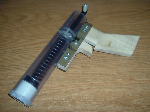
I'll add/edit/optimize the photos and provide links to references and other sources later. There should be enough info...for now.
Overview and Cost
This is a simple and basic blaster that has been commissioned in the past, but I haven’t seen any sort of write up for it. I’ve seen a lot of NoM’s commissioned Rainbow Pistols, and they all look super nice. This write up won’t address counter sunk black oxide screws, staining wood or fancy engravings, but will just be the basics. Perhaps, I’ll add a section later on customization if I do any fancy experiments.
This write up places the handle half an inch from the rear of the PVC main body of the blaster. I personally liked this look better, but relocating the handle further back on the blaster can reduce cost and size of the blaster.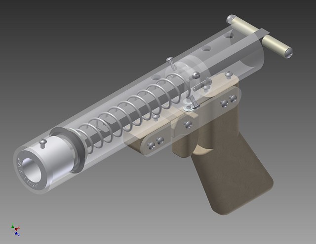
The blaster seen in this write up cost $16.82. Omitting the optional nylon washers would reduce the cost ~$0.38. An opaque blaster would bring the cost down a further $3.00. Changing the seal piece would reduce the price an additional $4.00. I anticipate the cheapest this blaster could be produced is $9.50.
The cost of materials to build one of these blasters is $138.11. This is not the cheapest possible. This is likely the best raw materials cost to produce the cheapest per blaster cost.
Tools
Required
• Drill
• Scroll-saw
• Screw drivers – ph2
• Tapping sets (#6-32, #8-32 optional)
• Sand paper
• Hacksaw
• 7/64” drill bit for #6-32 pilot hole
• 5/32” hole for #6 pass through screw holes
• Drill bit that your screw driver can fit through (5/16”)
• 9/64” drill bit for #8 pass through
Recommended
• Drill press
• Table saw
• Table Belt Sanding
• Hole saw – 1-3/8” or 1.5”
Materials
• 2x #6 x 3/8" Washers
• #6-32 Nylon Insert Lock Nut
• 12x #6-32 x 1/2" Machine Screws
• #6-32 x 1-1/4" Machine Screw
• 3x #6-32 x 3/4" Machine Screws
• 2x #6-32 x 3/8" Machine Screws
• #8-32 Nylon Insert Lock Nut
• #8-32 x 1.25" Machine Screw
• #8-32 x 3" Machine Screw or a 2.5” screw if you can find one
• 14 sq in 1 x 8 x 2 Poplar Board
• 1”- ½” PVC bushing
• 3/16" x 1-1/4" Fender Washer
• 2x 3/8" x 3/16" x 1" Nylon Spacers
• 8.5”x Black Delrin® Acetal Resin Rectangular Bar, 3/8" Thick x 3/8" Width
• Catch spring
• 5”x [k25] Compression Spring, Spring-Tempered Steel, 11.0" Long,.968" OD, .08" Wire
• 6.75 sq in Impact-Resistant Polycarbonate Sheet, 1/8" Thick, Clear
• 6 sq in Polycarbonate Sheet 1/4" Thick, Clear
• 9”x Std-Wall (Schedule 40) Clear PVC Unthrd Pipe 1-1/4" Pipe Size
• Stretch-Fit Rotary-Shaft Ring Seal 1" Shaft Diameter
Optional
• 8x Nylon General Purpose Flat Washer, NO. 6 Screw Sz, .32" OD, .05"-.07" Thk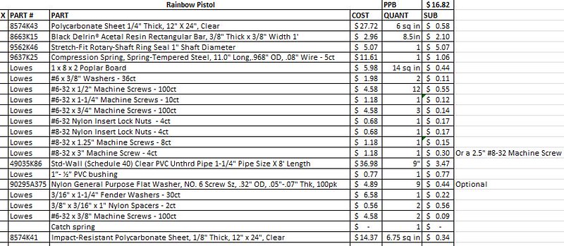
Important note: The reason I did not include a part number or anything for the catch spring was because you can use any spring you want. I used a small spring that I took from a different Nerf blaster. If you don't have any springs just lying around, you can use a spring from a pen if you can cut it down. It should be pretty easy. I've never purchased springs from McMaster for this purpose before, but I imagine you can find them.
Templates
Here are some different versions of the handle and the catch pieces. idw wasn't playing nice and wouldn't let me annotate the threads properly.
PDF Version
IDW Version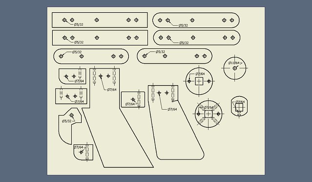
Procedure
Machined Pieces
You can either machine each piece before starting, or machine each as you go. I prefer to machine each as I go, unless mass producing any piece. But for clarity’s sake, I’ll just have you do it now until you’re more familiar with how to make each piece.
Apply the sticker templates to the polycarbonate on the indicated thicknesses. There are protective sheets on the polycarbonate. Glue or, if printed on adhesive backed paper, stick the templates on the polycarbonate. The rectangle side plates are the only pieces that need to be 1/8” thick. I’ve theorized using the 1/8” thick polycarbonate for the rear catch circle which may be possible. All other pieces are ¼” thick polycarbonate. The rectangle handle piece, trigger, and main handle piece are all for 1” wood – with a ¾” nominal thickness. You could look into what NoM has done with his handles and use polycarbonate for the trigger, but I’ll keep this guide basic.
The easiest way to machine the pieces is to first drill all the holes on the faces of the pieces. Drill the holes as marked. Then, use a table saw to cut the square rectangles, cut the front wood handle piece, and cut the wood main handle piece. The wood trigger is easiest to cut on a scroll saw. The catch pieces, circles and catch plate, are also easiest to do on a scroll saw. However, I’ve recently found using a hole-saw and turning it down on a lathe is easiest for the circles.
Each piece has little quarks that I’ve come across.
Side Plates
Drill and cut the side plates out of 1/8” polycarbonate. ¼” thick polycarbonate is useable and would be an easy option due to ¼” polycarbonate being also required for other parts of the blaster. The easiest way to machine these pieces is to cut them on a table saw and drill the holes with a drill press. Either drill all holes on the handle side plates 5/32”, or drill the middle hole 7/64” and tap for #6-32. If tapped, this allows the trigger screw to tighten or loosen on the trigger. I find that, depending on how the handle wood pieces are sanded, the side plates could end up being too tight on the trigger to allow it to rotate freely. This can be resolved by sanding the trigger smaller or increasing the gap between the side plates by adjusting the trigger screw. You’ll want to sand all the edges and corners down so that it’s comfortable – more on this later.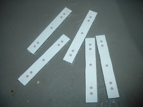
Handle Pieces
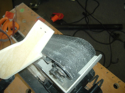
Drill and cut the forward handle piece, trigger, and handle. It is often easier to drill the pieces before cutting, because there’s more material to hold onto while drilling. However, the order isn’t important. All the holes are 7/64” except for the trigger which is a pass through for a #6 screw - 5/32”. The forward piece and handle are easiest done on a table saw and the trigger is easiest to cut out on a scroll saw. When the main handle is cut, drill the two holes on top. The holes in top of the main handle are easiest done in a drill press vise where the holes will be straight and the base of the handle will be flush. These, as well as all the holes drilled, should be centered and straight. Otherwise, your handle or other pieces could be ridiculously crooked and may cause friction, the screws to not align, or other problems. When the pieces are drilled and cut, sand them down. Smooth down edges and sand the trigger and handle so they are comfortable to use. I use Ryan’s original templates, but I remade them with more detailed markings - like center lines for example.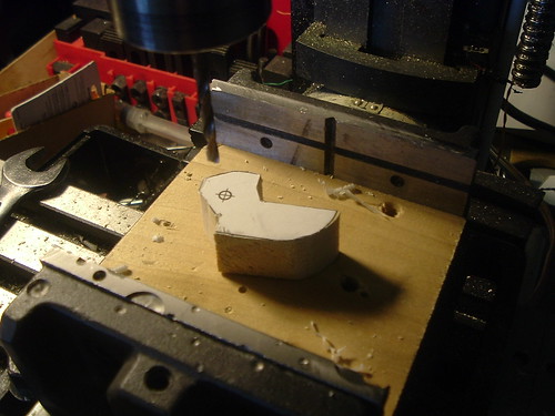
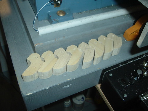
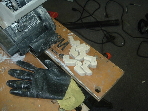
Only one of the top 7/64” holes in the forward wood handle piece is needed. The other hole, if used, interferes with the function of the blaster. Modification of some of the pieces may remove redundancy, but the templates were borrowed from Ryan and the parts I’ve mass produced are also interchangeable with my Rainbow Pump blasters. I will add this to the customization section.
The trigger’s flat top prevents the trigger from over traveling forwards. If the hole is drilled too high or the top cut is too low, than the trigger will be allowed to move forwards, which may be a minor undesired feature.
Catch Circles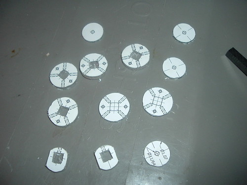
The catch circles are easiest to first drill the two 7/64” holes in each circle, then to cut them out with a hole-saw, and then to finally lathe them down so they fit in 1.25” PVC. However, if you’d like the practice or are good with a scroll saw, than it would be faster to simply attempt to cut the circles with it. If done with a scroll saw, it’s easier to drill a pass through hole for the scroll saw blade in the center of circles to cut out the square holes. I like the perfect roundness of lathes, but a scroll saw is faster and, with skill, is just as easy to make round. However, if cut with a scroll saw, it may be necessary to sand the edges down so that it fits smoothly into PVC.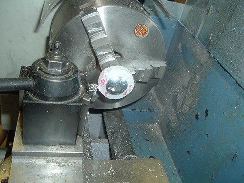
The catch plate is easiest to just cut out on a scroll saw after drilling a center hole. After all the pieces are drilled and cut, thread a scroll saw blade through the pieces and cut the square holes. I find it’s easiest to start the cuts diagonal first, and then square out the holes. Here are some pictures to clarify.
Drill the center hole.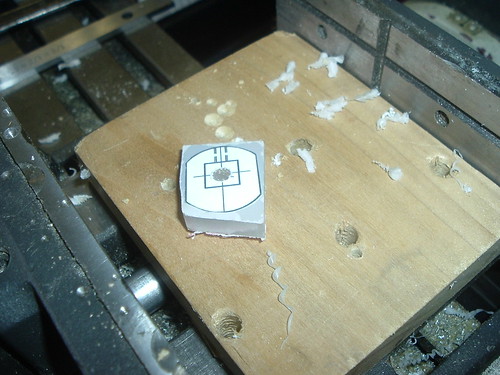
Cut diagonally.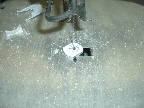
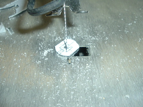
Shave out the inside of the squares.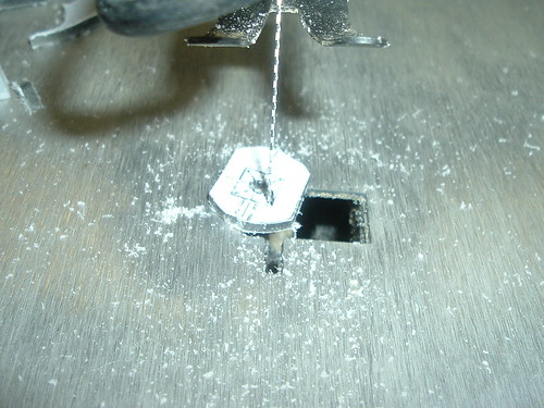
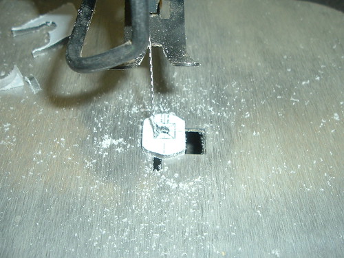
Then clean it up.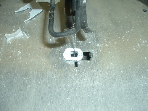
You’ll want to make sure that all the pieces are smooth and sanded well. They need to be able to slide across each other freely.
Also, while making each piece of the catch, you’ll want to make sure that the square holes fit the Delrin rod and that at each step, the catch fits in the PVC body or you’ll have to sand it down again.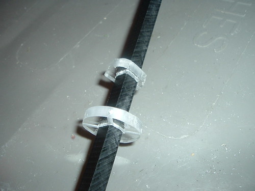
Plunger Head Circle
The easiest piece to machine is the circle of polycarbonate for the front of the plunger head. I find that this piece should be as wide as possible, but still allow the plunger head to fit into the PVC plunger tube. More on this later.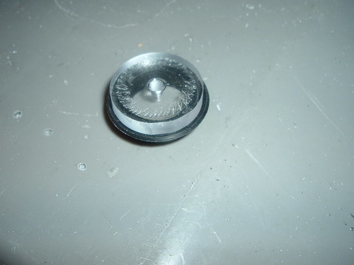
Handle
Handle Assembly
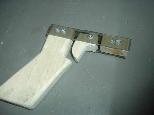
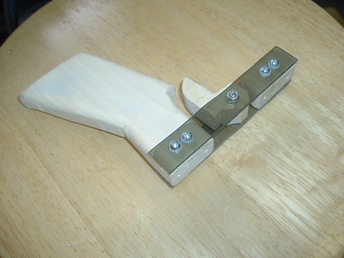
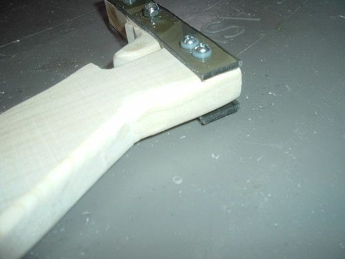
After the pieces are cut and all the holes are drilled, assemble the handle. Assemble the handle with eight #6-32 x ½” screws. Tighten well – I like my handles to not have any wiggle. I use nylon washers because I think they look nice and you wind up with a lot of extra washers from making a +bow. Omitting these washers reduces the cost of the blaster by ~$0.38. However, I’ve also noticed that the handle may be thinner than the 1” that these two screws would require and that the washers give a larger margin of error in the thickness of the wood or length of the screws. This is also another reason one may want to use ¼” thick side plates instead of 1/8”.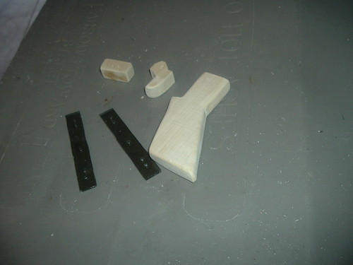

Catch
Cut
I know I’ve said some of this before, but here’s where it’s important.
Cut, drill and tap all the catch pieces. It’s easier to drill the two 7/64” holes in the catch circles before cutting anything out. Cutting the pieces out is pretty self-explanatory, but it took me a few tries to cut circles and such perfectly on a scroll saw. I’ve found that the easiest way to make the catch circles was to find a hole-saw and cut the templates out, then widdle it down on a lathe until it fit easily in the main body. The catch assembly and pieces should fit in the 1.25” PVC freely. One of the common pitfalls is machining the catch pieces. There’s quite a bit of margin of error, but the process can be made easier through a little bit of practice and technique. Just go slow and steady is the key. I find the easiest way to cut the square holes are to thread the blade through the center hole of the hole saw, cut diagonally across the squares, then ‘carve’ out the rest of the hole. Continuously test fit the 3/8” square Delrin rod into the catch pieces. For the catch plate, drill a pass through hole for the scroll saw blade, then cut the square hole.
Drill and Tap
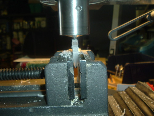
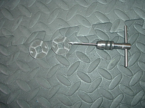
Drill a 7/64” hole centered through the bottom of the catch plate and tap it for #6-32. Also tap the holes in the catch circles #6-32. Make sure the holes in the catch circles are straight, otherwise, if you’ve originally made the circles perfectly sized, the misaligned holes could cause the circles to no longer fit. With all the work done on the catch, debur and sand all the edges and holes in the catch pieces so they are smooth.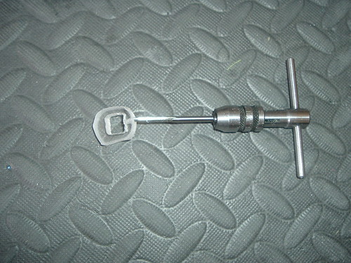
When I had originally printed out templates, they included diagonal holes for the screws to attach the catch to the main body. You can either drill and tap these in one of the catch circles, or simply wait to drill and tap them later – which would likely be easier, but I’ve done it successfully with either way.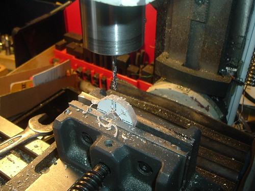
Assemble
With the catch plate as a guide, assemble the catch with two #6-32 x ¾” screws with a .25" gap between the circles. The catch plate should slide freely in between the circles.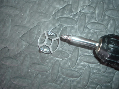
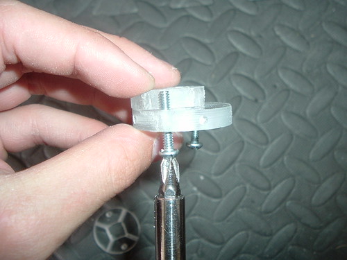
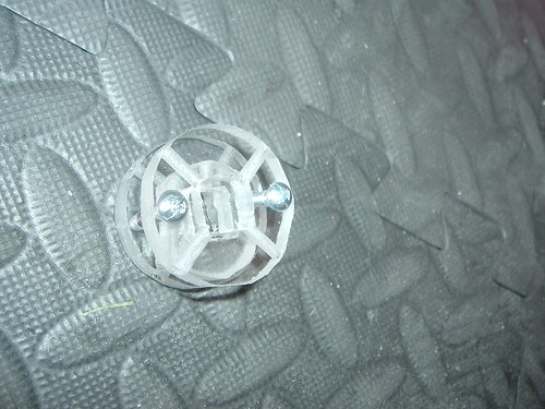
On the first Rainbow’s I made, I simply drilled the templates, cut the circles, and rounded them out on a table belt sander instead of a lathe. Using a table sander gave the advantage of being able to easily sand the catch circles as a whole assembled piece, if needed.
When the catch is assembled, it should still slide into the PVC easily. If the holes are misaligned and the catch is lopsided at all, hitting it with a touch of the sander can straighten it out to fit in the PVC again.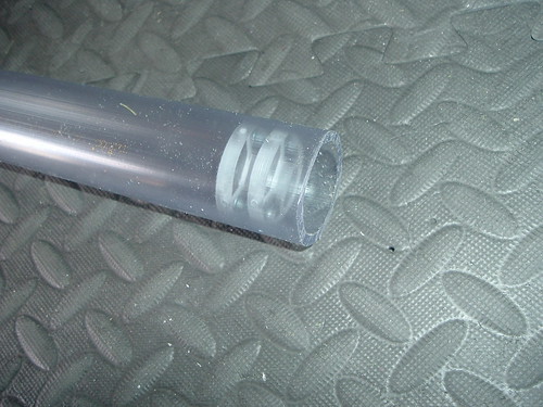
Main Body
Measuring and Marking
Figure out what spring you want to use. You’ll need to adjust the design to whatever it is you’re using. Take into account the length and pre-compression. The spring will change the length of PVC, the length of plunger rod, position of catch and subsequently the handle. I was thinking about creating some sort of program to calculate all the recommended dimensions based on inputting different spring and draw preferences.
I’ll be using 5” of [k25] with 0.5” of pre-compression.
I like any words on the PVC to be on the bottom of the blaster. Use a three sided ruler to mark the bottom. Then, use a marking rig to measure the body in eighths and extend these marks.
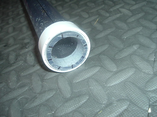
This write up places the handle half an inch from the rear of the PVC main body of the blaster. Make a mark there on the bottom of the blaster.
Place the handle on the mark and mark on the PVC where the holes in the wooden handle pieces are and where the trigger lines up.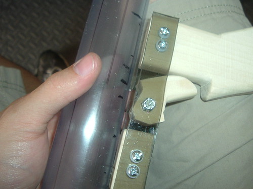
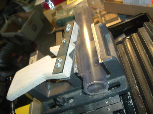
With the marking jig rig again, extend/copy the marks of the three holes to the top of the handle.
Drilling
Drill the marks for the handle on the bottom 7/64” and make sure the handle still lines up with those holes. These holes are the two closest to the back and the one closest to the front. Tap each of the 7/64” holes in the bottom of the blaster #6-32.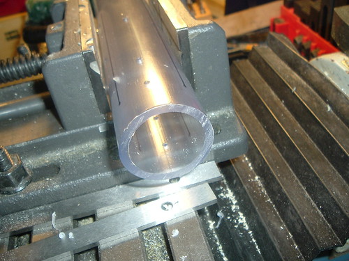
Then, drill the mark for the trigger 5/32”.
Flip the body over and drill the three holes on the top of the blaster to fit a screwdriver through. The position of these holes should be marked on the blaster and should be mirrored from where the holes for the handle are. These wider holes are for attaching the handle. I used a 7/16” bit, but a smaller hole would work if your screw driver is smaller.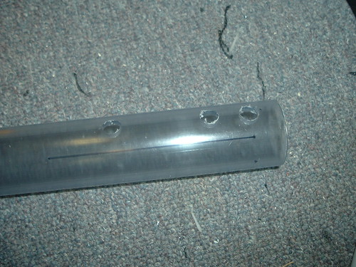
Catch
Take the catch, which should fit into the body, insert it with the threaded side of the screws to the front. If you’re wondering, the flat side of the catch will act as the rear spring rest.
Align the catch plate over the 5/32” pass through hole in the bottom.
Assemble the catch spring into the blaster and tighten it down so the catch stays in position.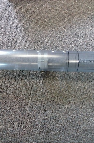
Then, with a 7/64” bit, drill all the way through the body and catch circle on the diagonal sides. In order to keep the catch centered properly when drilling the holes, I like to hold the position of the catch with small drill bits.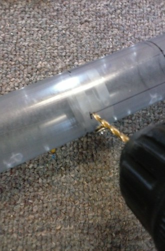
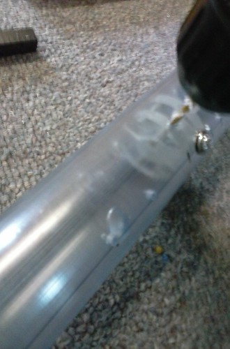
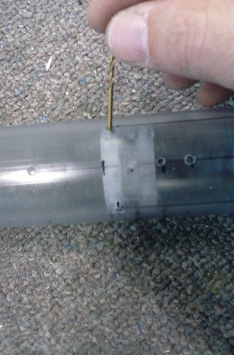
With the holes drilled, now here there are a few choices. Remove the catch and tap the PVC and polycarbonate. If you did not drill and tap the catch circle before, you can remove the catch from the body and tap the holes. Or, simply tap the holes through the catch. Either way, put threads into the PVC and catch. You will need to push the catch out of the PVC with something long and skinny.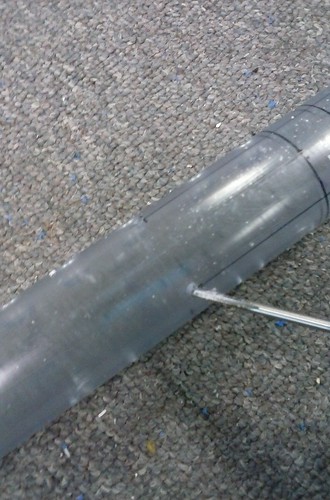
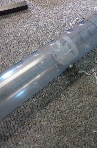
Attach the catch with four #6 x 1/2” machine screws.
Make sure that the affixed catch can fit the 3/8” Delrin rod freely and without friction. This shouldn’t be an issue if you test fit as you go and make sure you drill and tap all the holes properly.
At this point, you can remove any sharpie marks with alcohol.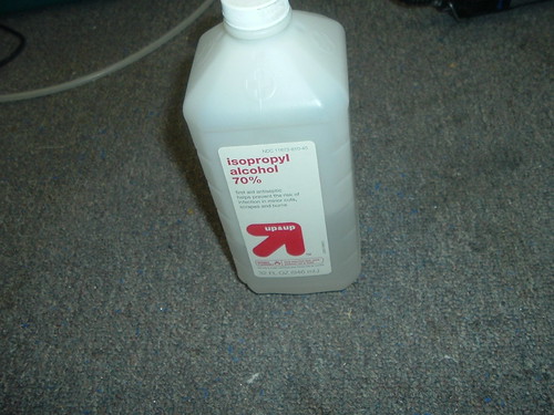
Attaching Handle
Attach the handle with three #6 x ¾” machine screws.
It’s easiest to do this by holding the blaster upside down and starting the screws partially into the body.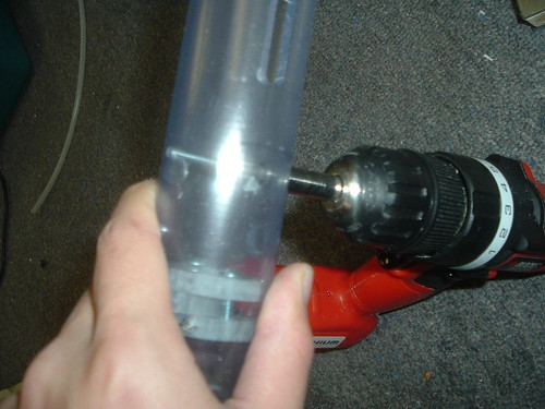
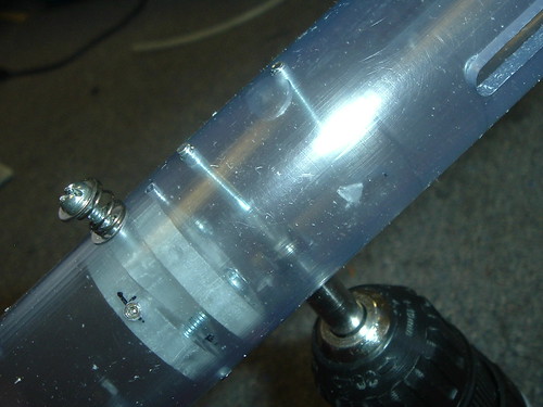
When the screws are held into the body, I like to press the handle against the body and tighten the front most screw first, then the rear most, and finally the middle.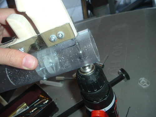
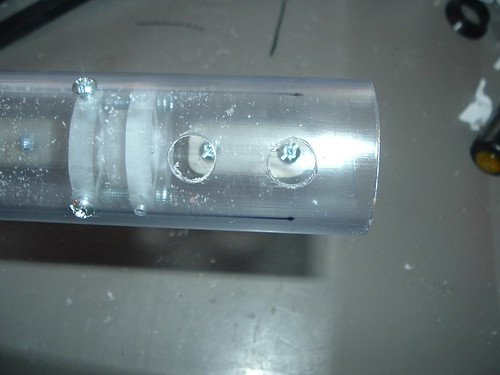
Make sure that the trigger is oriented properly, and not angled when you attach the handle.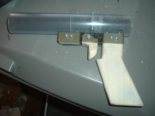
Plunger Rod
At this point, I like to make the plunger rod next. This will determine the draw length and placement of catch.
Cut the section of 3/8” square Delrin to length – 8.5” is what I used. The length mostly effects how much finger room you have to grip the nylon pull back handles.
Then, mark the center of one end of the Delrin – which will be called the plunger rod (PR) from now on.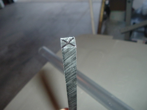
Drill two holes into the plunger rod. One in the center of the end of the rod for the plunger head, and one for the pullback handles.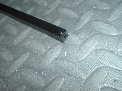
I like to use a #8 sized screw for the front of the plunger (or plunger head/PH) because its wider diameter helps keep the PH centered. Drill a 9/64” pilot hole approximately one inch deep into the Delrin and tap it #8-32. Keeping the hole drilled and tapped centered will assist in making the air seal as perfect as possible.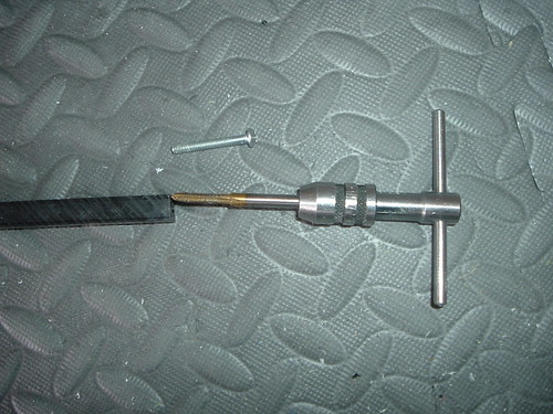
Drill the second hole 11/64” pass through hole for a #8 screw centered on the rear end of the Delrin rod.
Plunger Head & Catch Notch
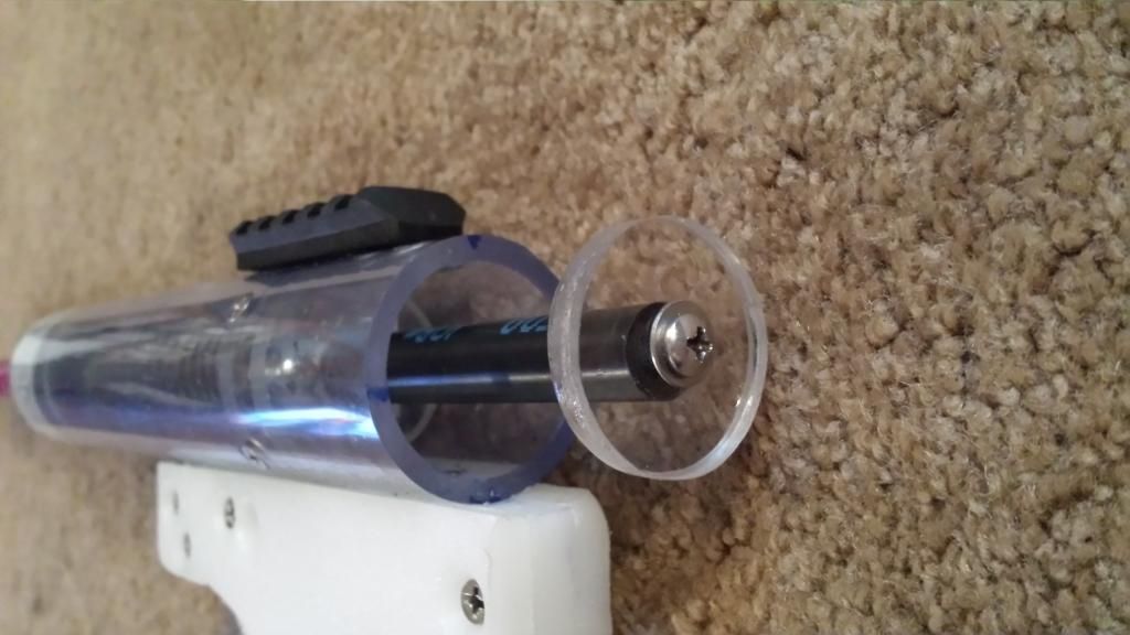
Create another ¼” polycarbonate disk that fits onto the top of the rotary shaft ring seal.
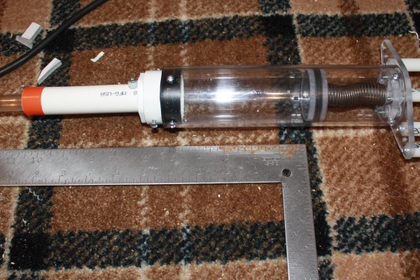
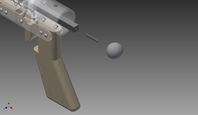
Then, assemble the plunger head as pictured. A 1.25” x .25” metal fender washer acts as the spring rest and supports the skirt seal, the rotary shaft ring seal creates the air seal, the small section (11/64”) of 1” OD 7/8” ID tubing keeps the skirt seal from buckling inward on itself and ruining the air seal, and the polycarbonate disks in front squishes the skirt seal which seals the two holes in the top of the skirt and compresses the skirt which flares it outward, which helps the seal. I’ve found that making this piece as perfect as possible goes a long way to making the seal perfect. The front polycarbonate disk flares the seal outward and presses it into the walls of the PVC body. Without the tubing piece, the skirt seal sometimes buckles inwards and causes one side of the skirt to not seal probably. With a proper polycarb disk on top combined with a tubing piece of the right height, the seal is perfect and low friction. If the plunger head when lubricated has too much friction in the PVC, take down the OD of the polycarb disk slightly and retest fit it. This method seems to create a 100% seal perfectly, every time.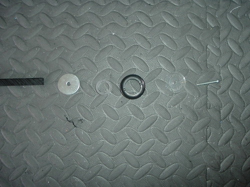
Test fit this whole thing by lubing up the seal and inserting this plunger rod into the plunger tube, from the front. It should be a fairly tight fit, but should slide.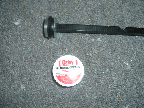
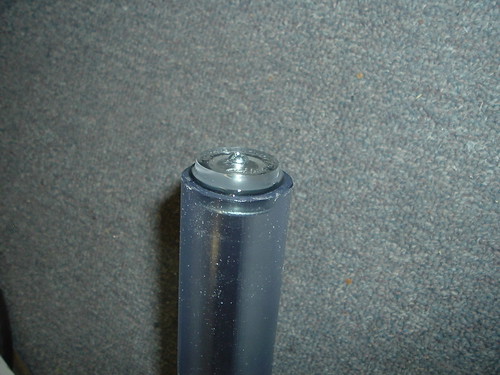
Test the compression of your spring and gauge where the catch notch in the rod needs to be.
I cut my notch for a 5” long [k26] with ½” pre-compression 1.75” from the plunger head. Keep in mind the thickness of the catch plate and catch circles. You’ll have to account for the added ½” in your measurements.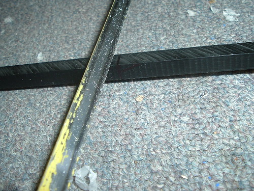
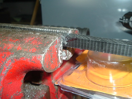
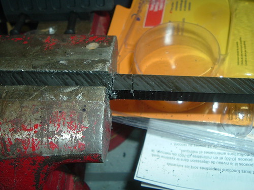
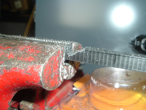
This notch is cut too deep.
With the spring and plunger rod properly fit in the body. Place the nylon spacers, #8-32 x 3” machine screw, and #8-32 locknut into the hole of the plunger rod. The machine screw will be too long, so hacksaw it down to a better size. Unless you can find a #8-32 x 2.5” screw, but I’ve been unsuccessful.
Front Bushing
The last, and arguably the most important step of a Nerf blaster is the front seal. There are a few different ways to create this seal. One involves plumber’s goop and tape of some sort.
Either sand down the lip of the bushing or have it stick out.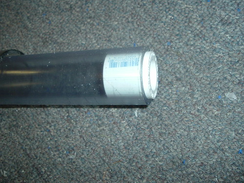
Wrap the base of the bushing in packing tape (or electrical tape, but I’ve found packing tape to be better).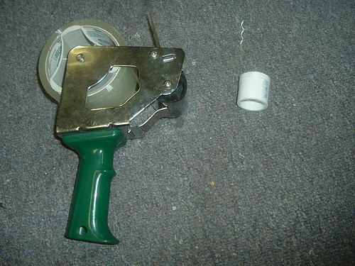
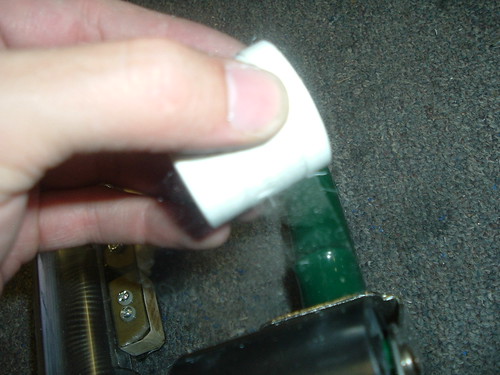
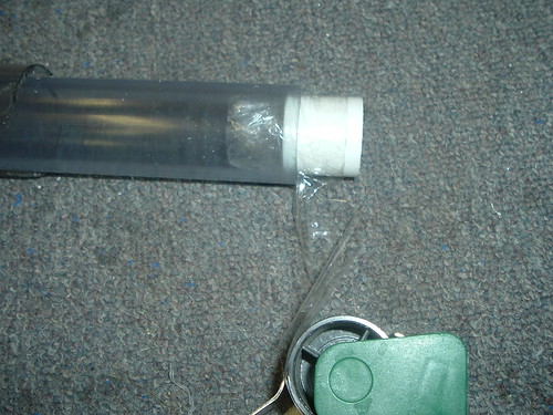
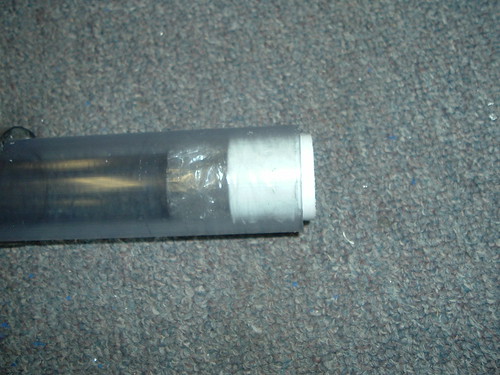
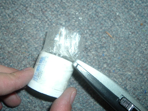
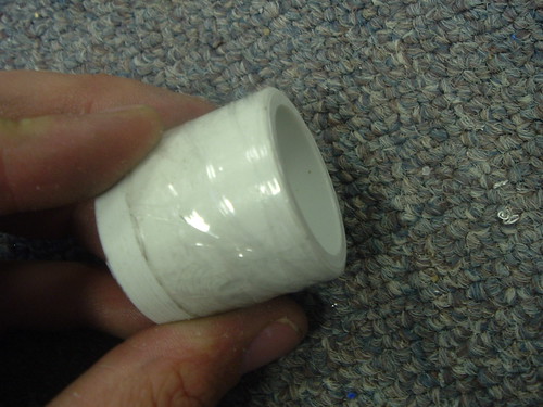
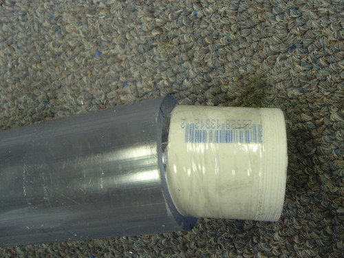
Apply goop around the bushing and insert it into the front of the PVC. Apply any excess goop that leaks out around the seam of the front to ensure it seals properly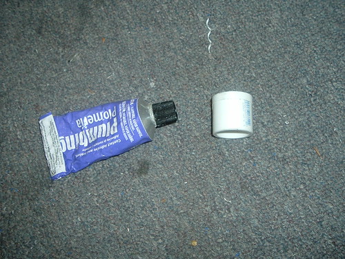
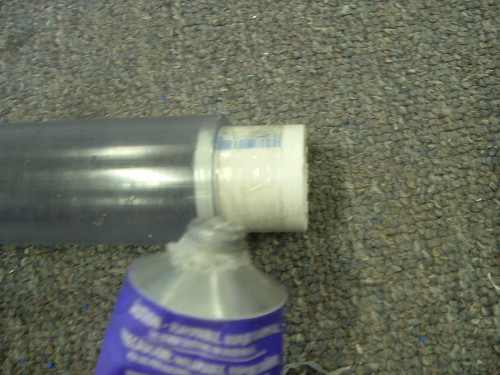
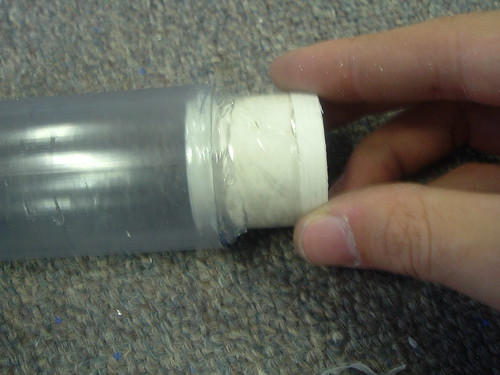
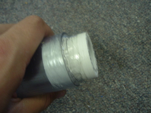
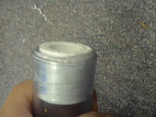
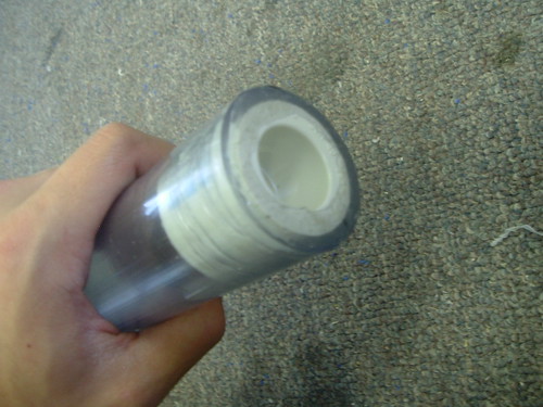
On the top and the bottom, measure ½” from the front of the bushing and drill two holes into the bushing 3/8” deep. I like to put the two screws for the front bushing on the top and bottom because if the screws were placed on the sides and the blaster down, the heads of the screws can scratch a smooth surface if the screw heads are not smooth.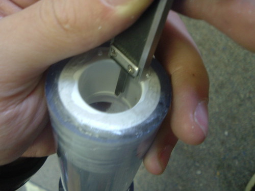
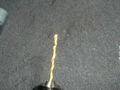
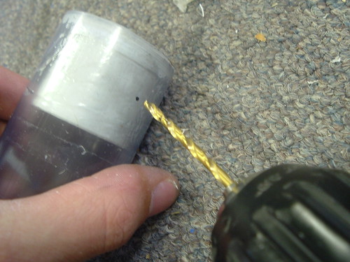
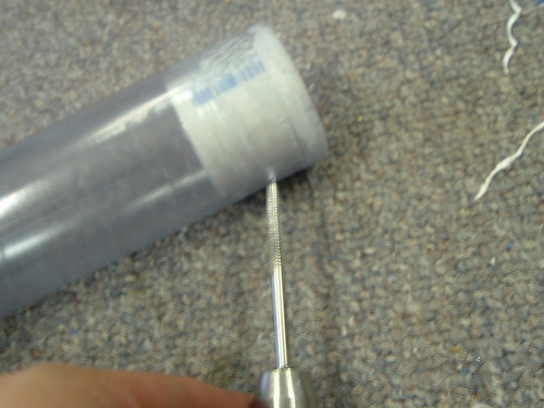
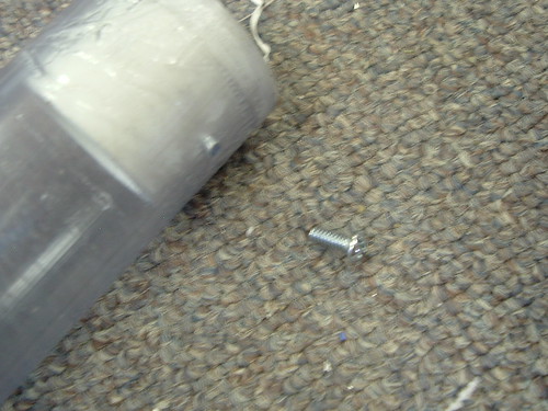
Screw in two #6-32 x 3/8” machine screws to attach the front bushing. I find two to be enough. One would be too little, and I haven’t noticed that three provides any benefits.
By drilling the holes exactly to depth and not tapping them, it allows the fit of the screw in the hole to be tight enough that it helps the bushing to seal around the screw and it also creates slight ‘squishing’ of the bushing that increases friction in the bushing which can keep ½” PVC in the bushing better.
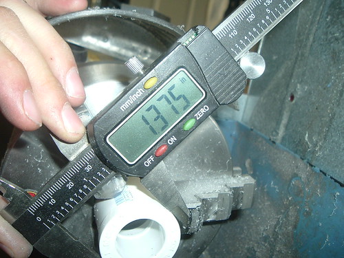
The second method, and the method I am still not sure how to perfect, involves just sealing and attaching the bushing with friction. Basically, it’s just hammering the bushing into the front of the PVC. Wrapping the bushing in tape can help keep it centered. The friction of the lip on the bushing creates a perfect seal with the PVC and the lip is wide enough to keep the bushing centered. However, I’ve found that, depending on the exact dimensions of the PVC and bushing, the force caused by the difference in size can actually cause the PVC to crack and ruin the blaster. The ID of the PVC is 1.335” and the OD of the bushing is 1.375”. I’ve lathed down the bushing to 1.365”, but there wasn’t enough friction to keep the bushing in place when pushing on a wye or barrel. However, it didn’t crack after several days, so there is room for a wider bushing that could work. The bushing sealed, but did not stay in place. Opaque PVC has a wider ID than clear, so that also causes a difference. Some pictures of the process: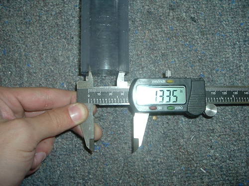
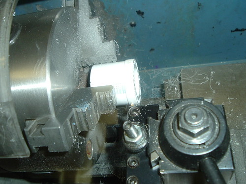
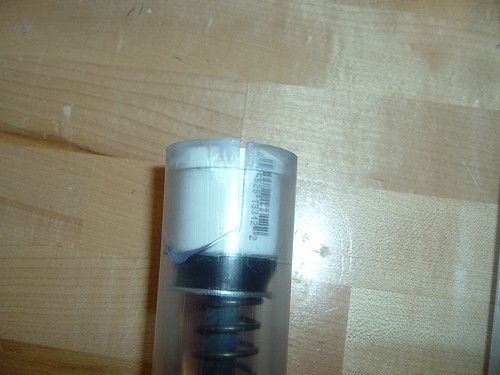
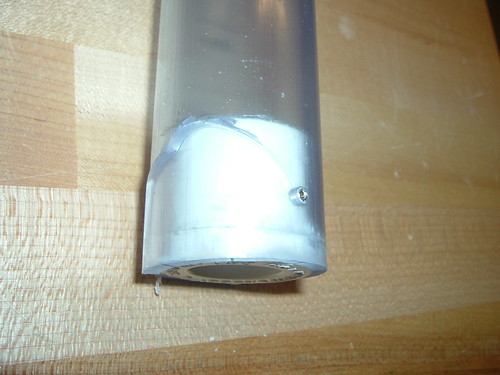
After the bushing is dry and sealed, the blaster is done.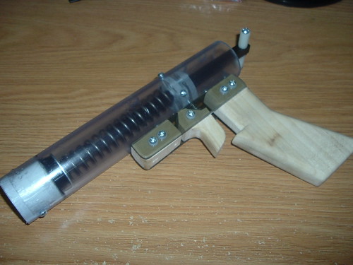
Maintenance
If excess dirt gets in the plunger tube/pressure chamber/main body/PVC, the front bushing can be unscrewed and removed by hammering or banging the rear of the plunger rod. I’ve done this several times without breaking the plunger rod and having seen any adverse effects. With the bushing removed, you can unscrew the pullback handles then remove the plunger and do whatever cleaning or replacement/repair you need.
Performance
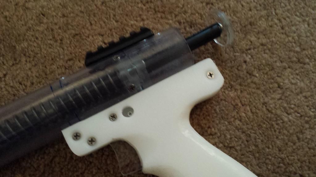
I’ve found that my Rainbow Pistol shoots amazingly well. Much better than I originally thought it would. I used it at ‘geddon and loved it and have used it in local wars to great effect. It’s a great loaner blaster - powerful, accurate, easy to prime, small, and, coupled with a loading mechanism, decent rate of fire. It’s comparable to a panther, but slightly bigger, less range, and is easier to prime which gives it a greater RoF.
Barrel
I found the optimal barrel length (at least with my darts and a fairly tight batch of CPVC) is ~8.5” and can achieve ranges in the 80s consistently. In my ventures, I’ve found three different fits of CPVC. All three have different ID’s and I’ve find the tighter the fit, the better. I hammer the CPVC barrels into sections of ½” PVC. The fit, in the right brands of ½” PVC, is such that it stays together and seals with no further effort. One batch of the CPVC had an OD of less than 5/8” and required finding a batch of SCH40 ½” PVC that had a slightly smaller ID than regular and I had to CPVC/PVC cement the two together. If glued well, the two brands seal despite a large clearance.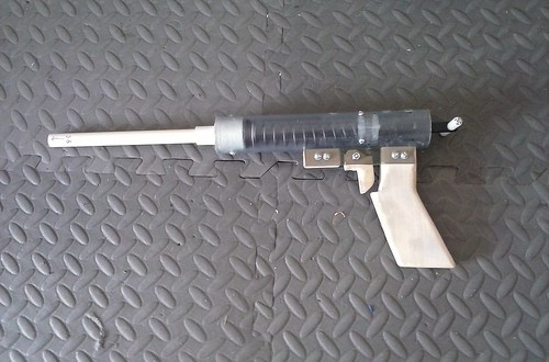
Speed Loader
I like old fashioned speed loaders. It reminds me of the time when most people used simple speed loaders all the time. It’s my favorite method of loading pistols and I’ve used them a lot on CPVC couplered Nitefinder pistols.
The easiest way is simply taking 1.5” sections of SCH40 PVC and mallet-ing 8.5” sections of CPVC into them. The fit of these brands is such that they stay together. I then PVC/CPVC cemented them together and held them in a vise until they dried. The bond was quite strong, but to be sure, I then wrapped it in stylish tape.
RSCB
These are a fairly dated technology, but this was the first real RSCB I’ve made so I thought I’d share. Instead of just sticking ½” PVC fittings and pipes into each other, I stuck a variety of different pipes into each other to decrease overall size and dead space. I took a ¾” length of ½” SCH40 PVC, hammered it in a 1.25” length of ½” CPVC, added a CPVC tee, glued it into a ½” PVC tee, added a barrel and loading tube. I cemented in all the fittings and CPVC sections.
To adapt the barrel to load from the RSCB, I took a ¾” countersink and reamed the CPVC/PVC. I then took a large step less drill bit to create a smoother loading for the dart. I’ve found this is necessary because the dart seals better and loads much more reliably.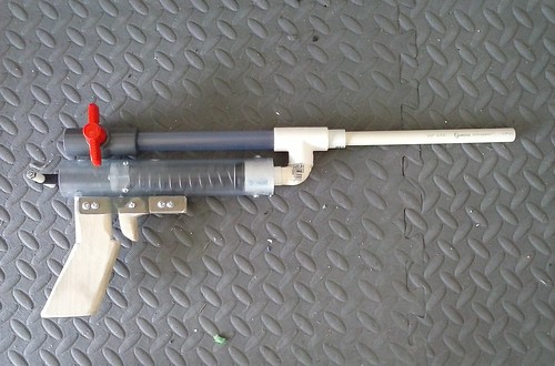
You may need to modify the design to stop darts from getting stuck in the tee, but I've found that it happens rarely enough that it's acceptable - but it does happen.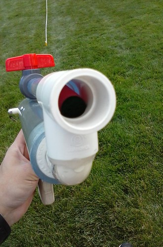
Slide Breech
Drill the ID of a section of ½” PVC out to 5/8”. The easiest way I’ve found is with a lathe and drill bit. I’ve used a steady hand and a 5/8” spade bit effectively as well. Cut a rectangle in the PVC. The size of this cutout section depends on the size of darts you intend to use. I start the cut by, obviously, marking and measuring it out first. I put the rectangle ~1” from the end of the PVC. This gives room to insert the breech into the bushing and a little extra so that it doesn’t feel too crowded. You’ll have to account for this extra distance when cutting the slot.
Cut the rectangle to the shape and size you want. I use a Dremel for breeches. There’s not another way I can think of to cut the slot.
I add a locking lug to keep the breech from opening due to air pressure from a tight dart fit.
I add this by cutting a semicircular in the bottom of the slot in the ½” PVC with a Dremel or drilling it with a bit.
I then drill a small hole for a small screw in the CPVC barrel. I close the breech and mark where the lug hole is. I then take a small nylon spacer and attach it with a small screw. It’s hard to find a perfect spacer and a perfect length and size of screw, just make sure the screw doesn’t stick too far into the CPVC and a dart can slide in. A breech can be considered either complex enough to need a write up of its own, and I’m sure there may be one, or several, write ups already. Or it can be simple enough to not need one and I’ll assume the latter.
One thing you should do is ream the CPVC to make it much easier to load and it makes a big difference. The darts will slip into the CPVC and angle right into the breech instead of potentially getting caught on a square edge.
Hopper
I’ve never tried to hoppered a RBPistol before. I imagine it would be possible with a low capacity hopper and will update this section when I try.
Edited by Naturalman7, 01 November 2016 - 10:41 PM.


