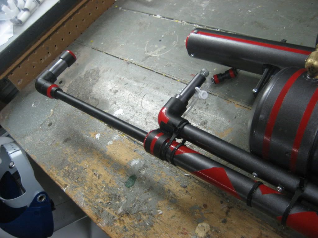
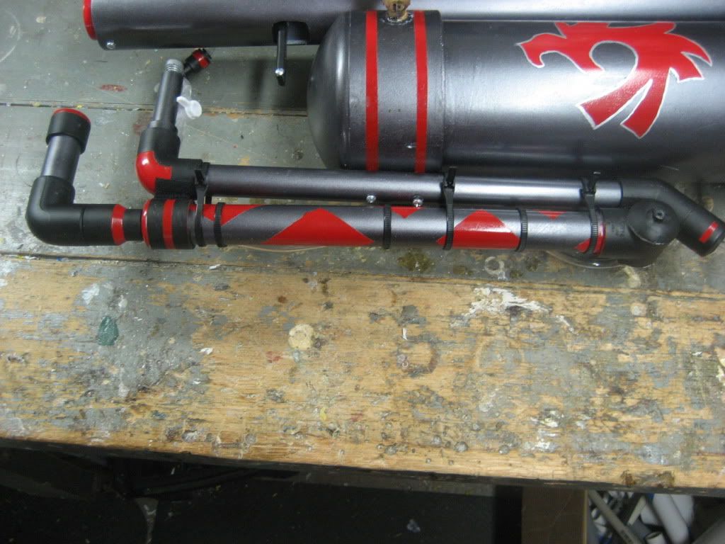
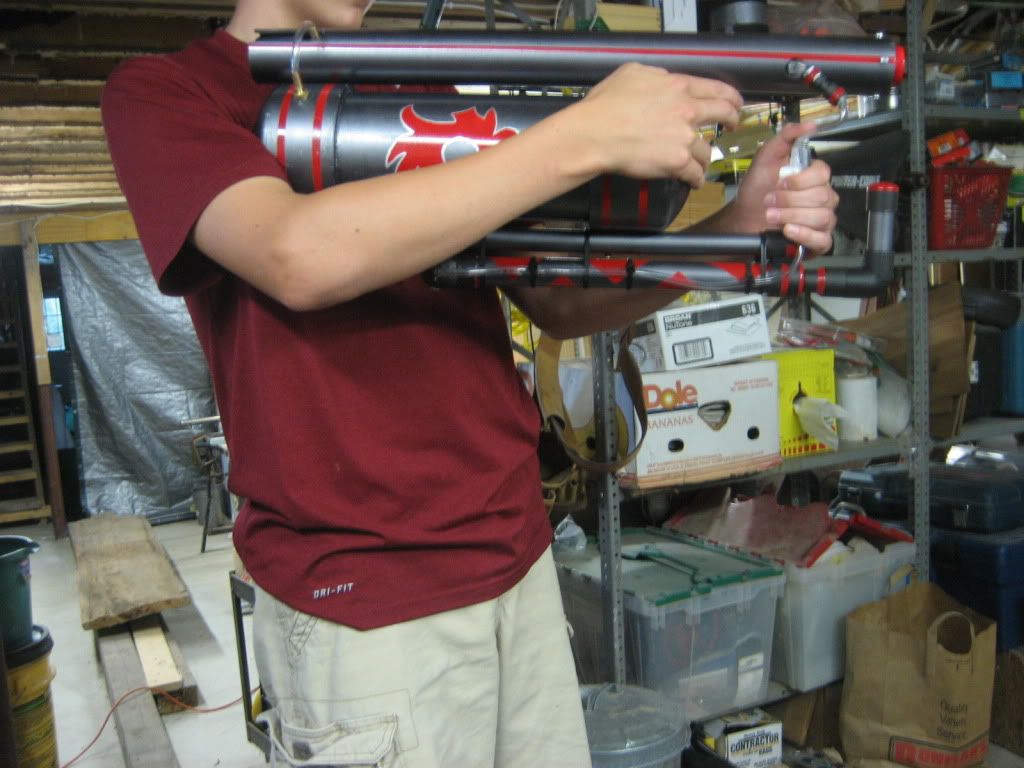
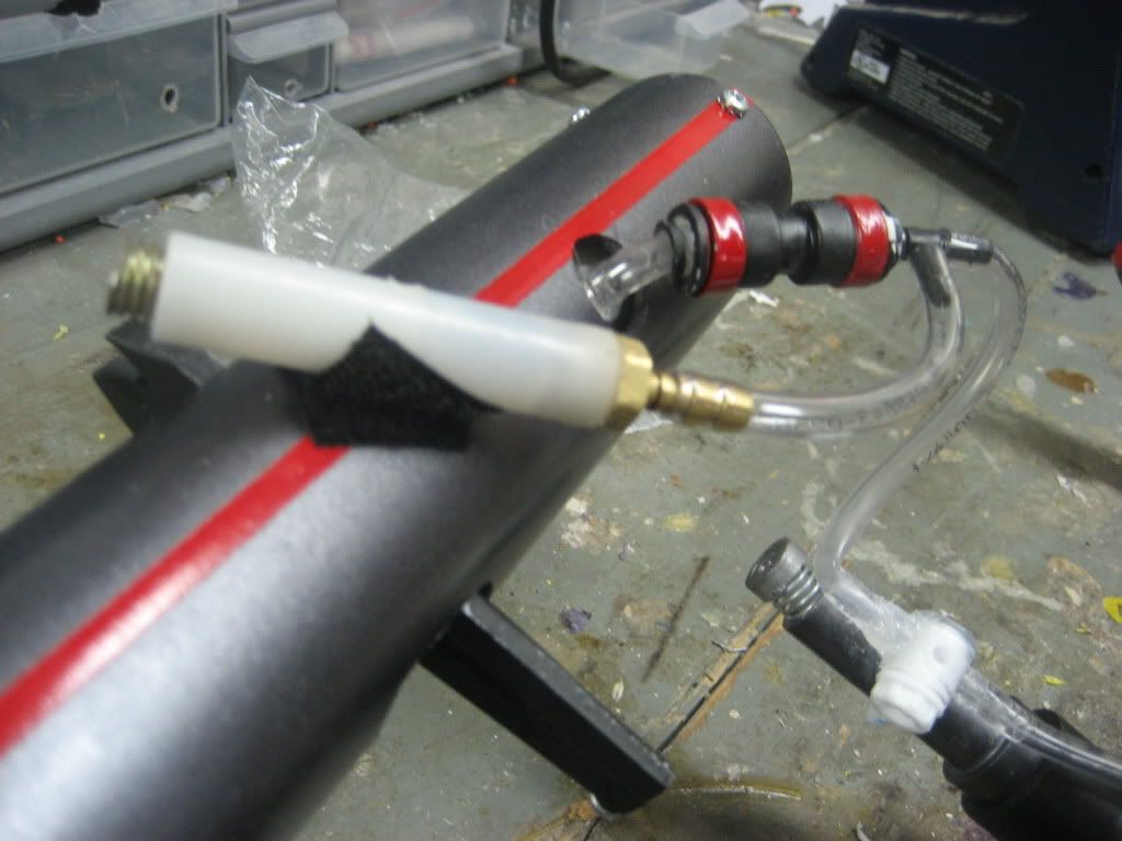
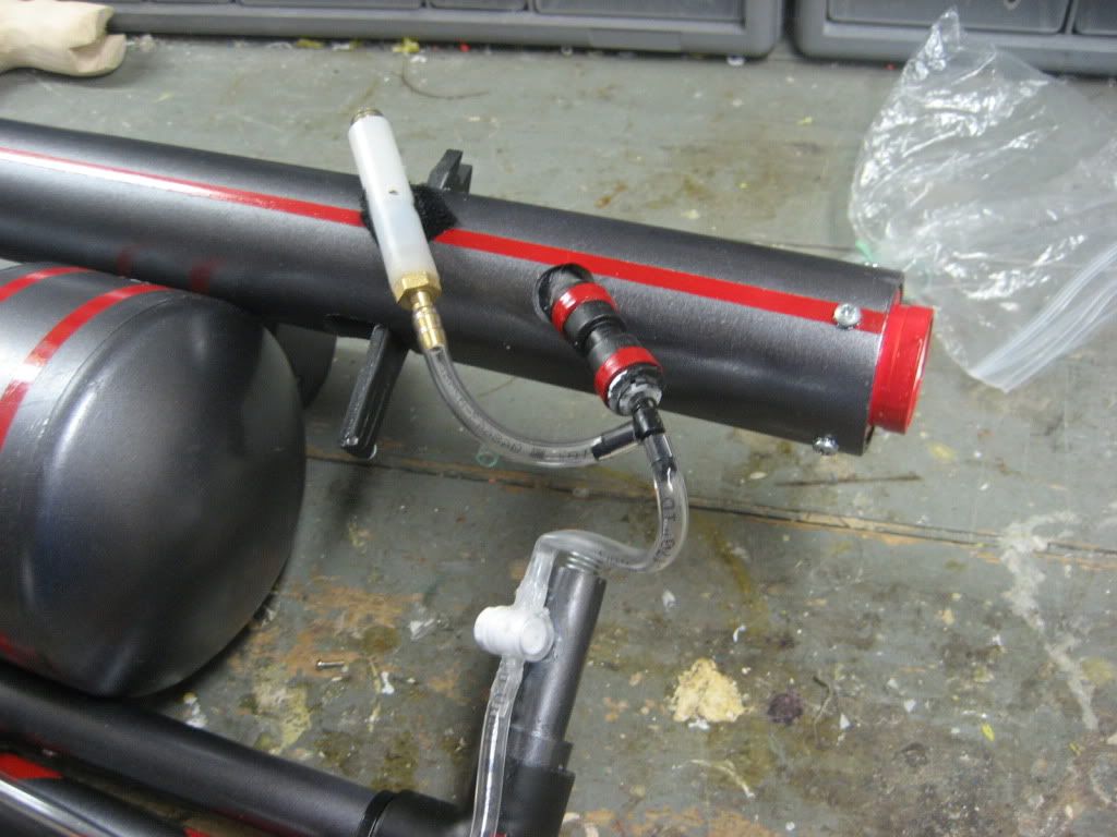
Preface:
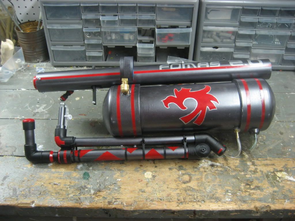
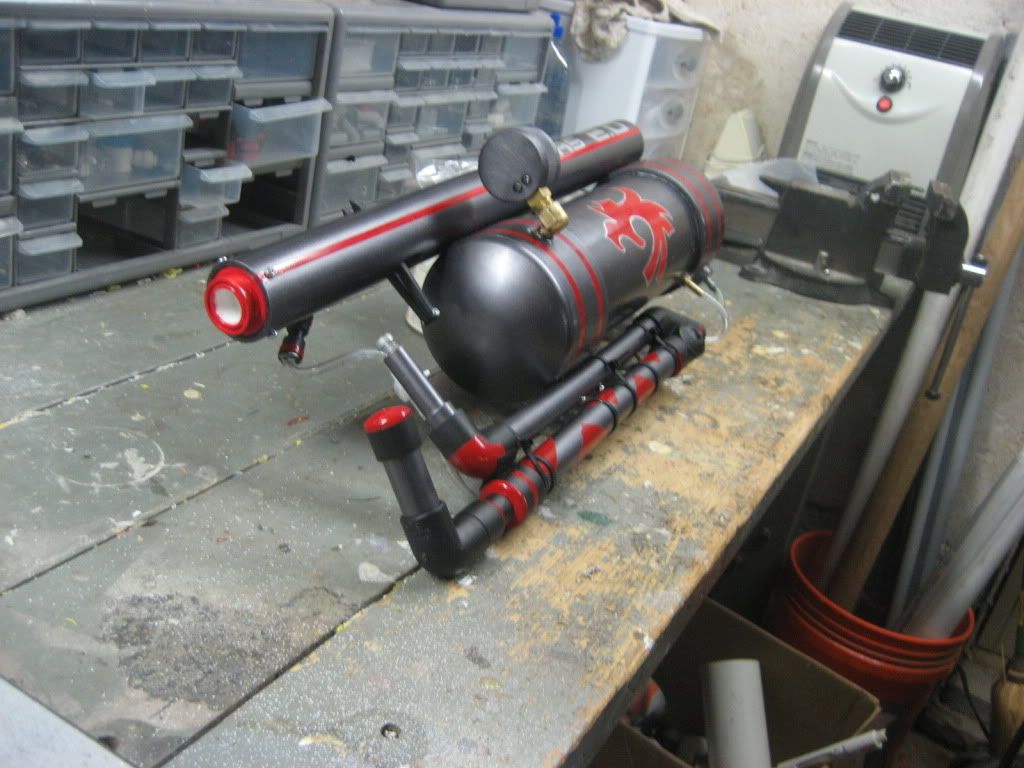
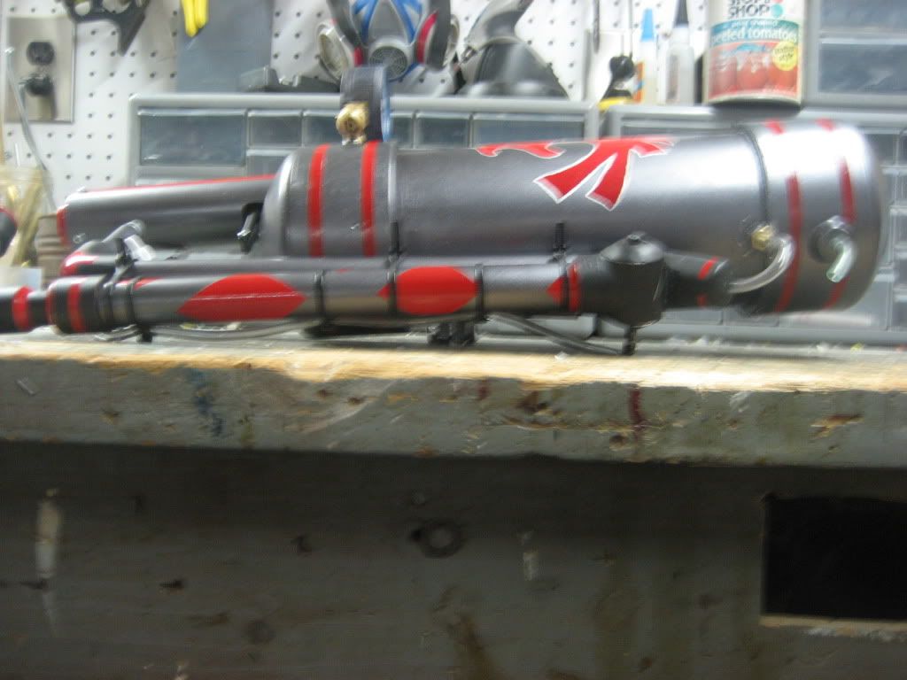
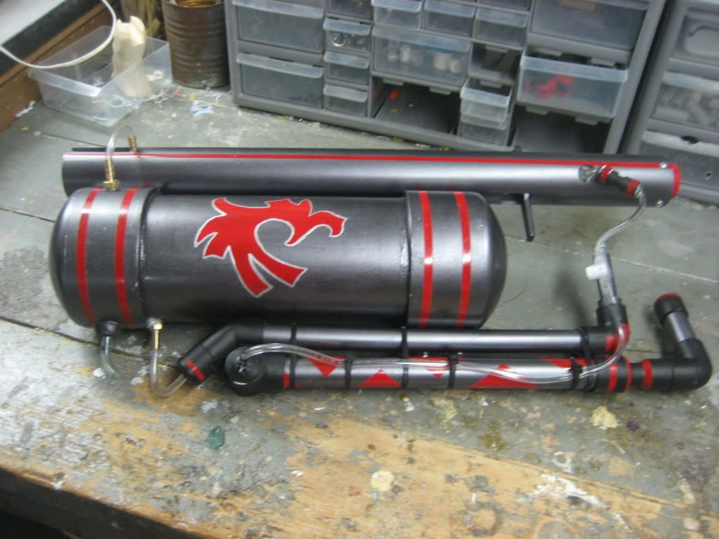
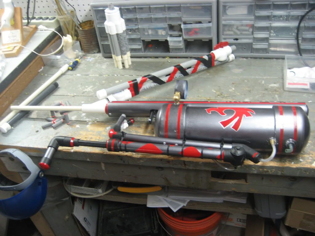
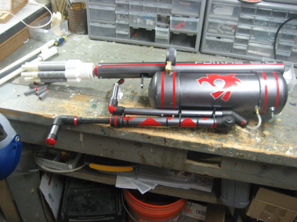
When I built the original FOMAS, I was aiming for a relatively cheap, relatively easily reproducible homemade airgun. Utilizing a modified version of Lt. Stefan’s PVAT, a Titan pump, and a rough interpretation of the templates for the L+L provided by CaptainSlug, I believe I succeeded. The FOMAS 2.0, however, was created, basically, because I saw potential in the original FOMAS to be something more than a standard “pump up the tank and pull the pin” air blaster.
Credits:
Lt. Stefan - It was his design for the PVAT and idea to somehow turn it into a functional gun that inspired me to implement it.
Ricochet - The valve connecting the airtank to the PVAT was his design. His video writeup for it is superb.
Links:
Original FOMAS - http://www.nerfrevol....php?f=9&t=2528
PVAT- http://nerfhaven.com...=1
Richochet’s valve -
McMaster - http://www.mcmaster.com/#
Ark-Plas plastics - http://www.ark-plas.com/
Parts list:
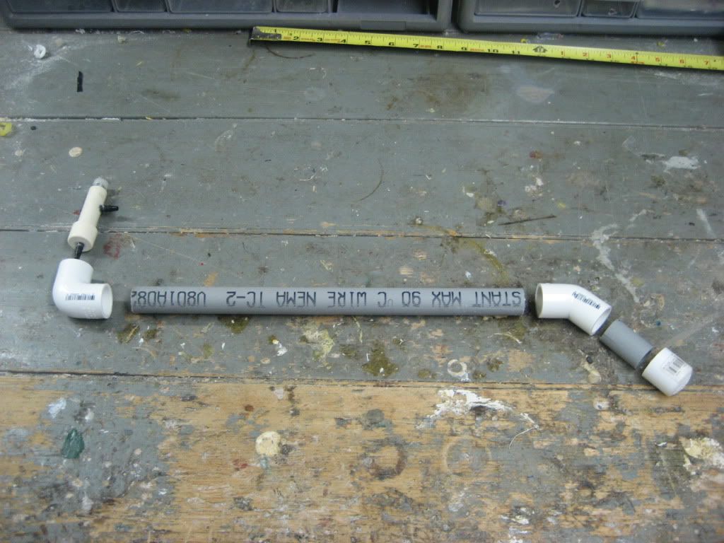
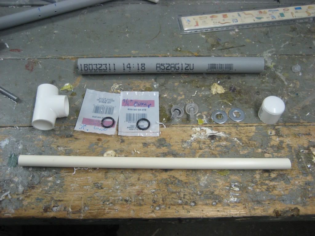
- 1x PVAT – I would recommend also getting an o-ring to help the front seal (see below for dimensions)
- 1x Ricochet’s valve (you DON’T need a barb for the side)
- 2x 4” PVC endcaps
- 13 “ of 4” PVC
- 2x 1” PVC endcaps
- 15” of 1” PVC
- 1x ¾” PVC tee, endcap
- 12” of ¾” PVC
- 1x ½’ PVC endcap, 45 degree elbow, 90 degree elbow
- 12” of ½’ PVC
- 1x ¾” CPVC endcap, 90 degree elbow, ¾” to ½” reducing coupler
- 2 pcs. Of ¾’ CPVC, one 2 1/4” and the other 1 1/4”
- 13” of ½” CPVC
- ¼” polycarbonate
- 2 ft. of 9245K51
- Metal washer- ID between 3/16” and 1/4” (either will work), and OD between 7/8” and 1” (same as before)
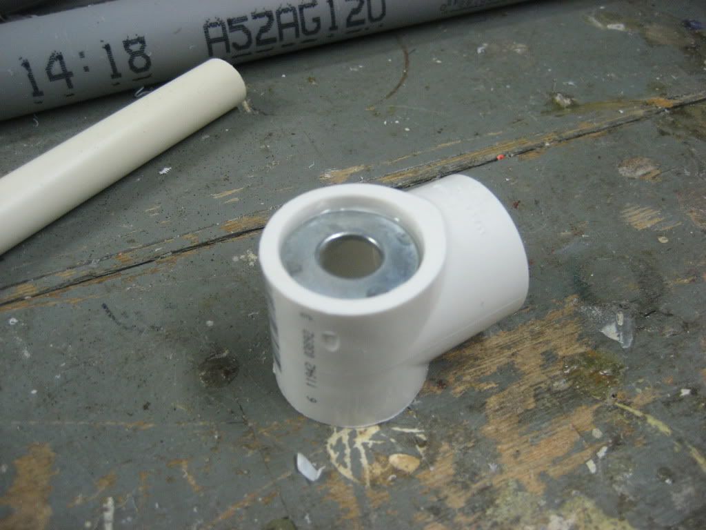
- 2x metal washers w/OD that fits into a ¾” tee and is held by the lip, ID just has to hold the checkvalve
- Assorted 6-32 thread screws – 2x 1”, 4x ¼”, 4x 3/8”, 1x1/2”
- Your choice of size in vinyl tubing, brass/plastic barbs (x3), and quick connect fittings (x1). I used 3/16” ID, ¼” OD tubing to increase airflow a little, but 1/8” ID tubing and fittings would work fine as well.
- LOTS of electrical tape
- 1x 13/16” OD, 5/8” ID o-ring for PVAT
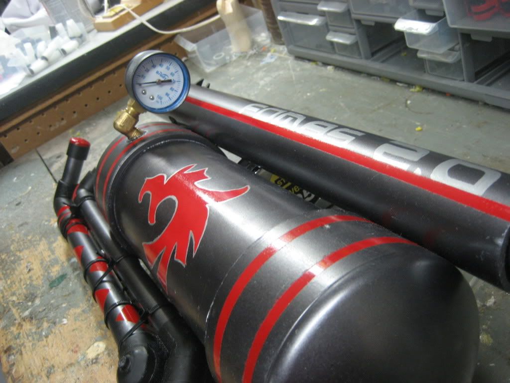
- 0-100 PSI guage
- 3x check valves, only 2 have to fit your tubing size (AP19CV0012NL for 1/8”, AP19CV0018NL for 3/16”)
- 1x 3 way toggle valve (AP12SCL3SSSCL)
^^^These items can be easily sourced from Ark-PLas plastics (link in preface) for FREE. The company offers free samples, and you simply add the items to your samples cart, give them your address, and they pay for shipping to you.
TOOLS (necessary and Optional):
- Something to cut plastic tubing with (coping saw, bandsaw, crosscut/chopsaw, pipe cutters, etc) - Necessary
- Belt sander - Optional
- 6-32 tapping bit – Necessary
- Assorted drill bits – Necessary
- Drillpress or drill – Necessary (drill probably more practical for this application)
- Adhesives: superglue, PVC cement, PVC primer, epoxy putty, GOOP - ALL necessary
- Hot glue gun and hot glue - Necessary
WrIteup
PVAT and trigger
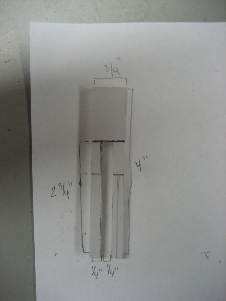
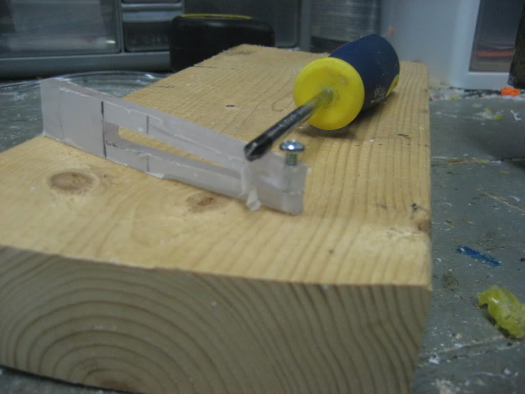
We will start with the trigger. The following picture is self explanatory. After doing this, drill a 7/64” hole through the two prongs at the bottom, thread one of the holes with your tapping bit, and enlarge the other to 5/32”.
READ BEFORE BUILDING THE PVAT:
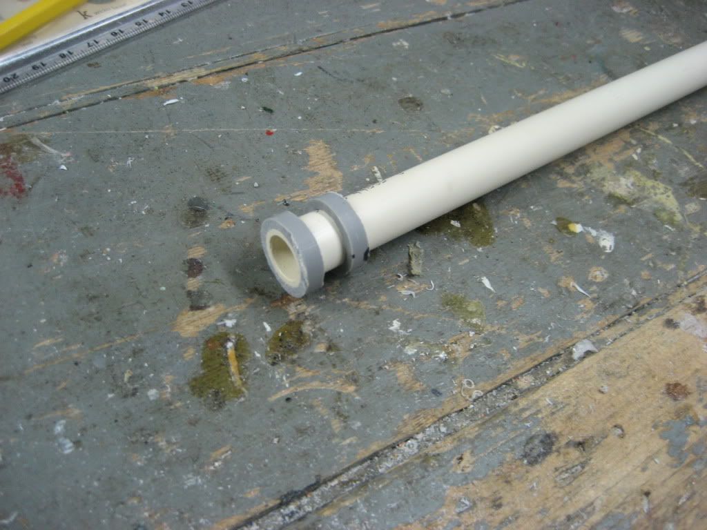
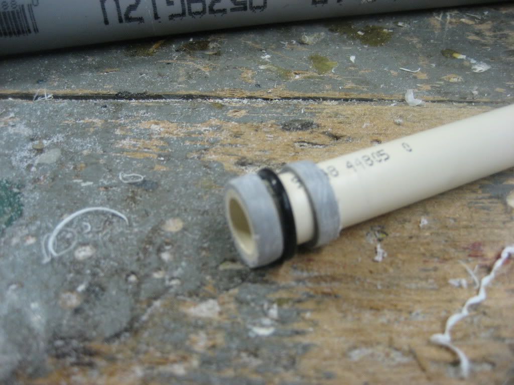
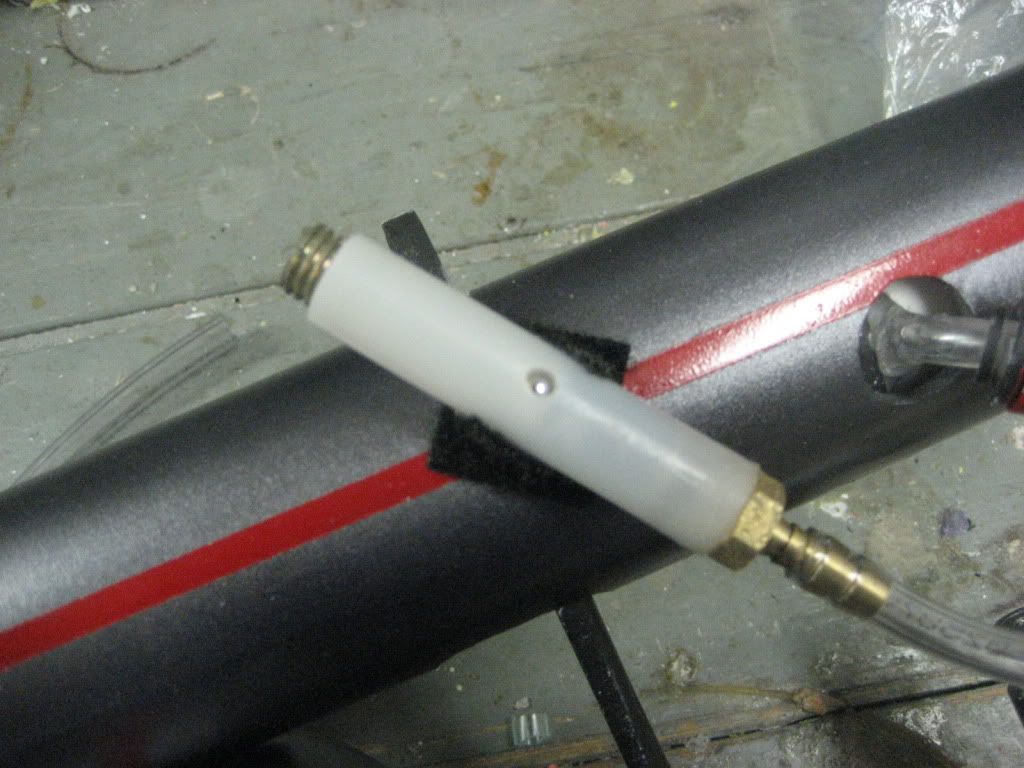
Insert an o-ring into the front coupler part of the PVAT to help the seal
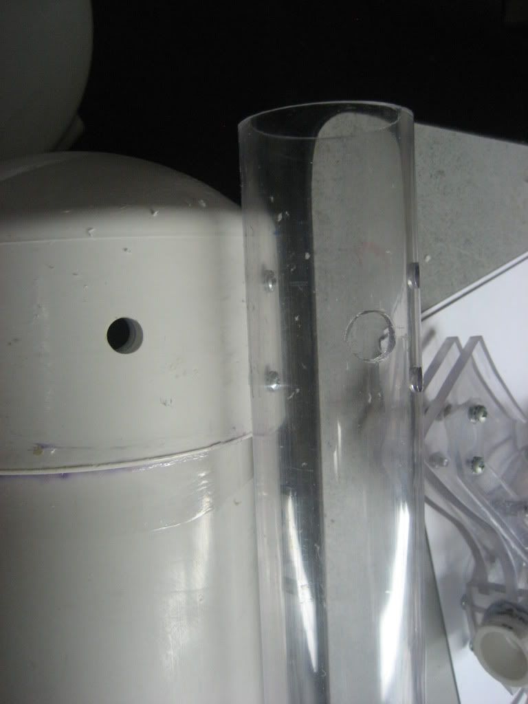
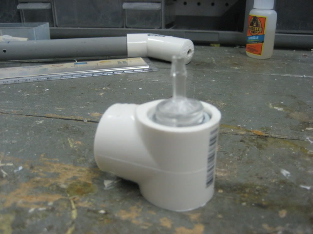
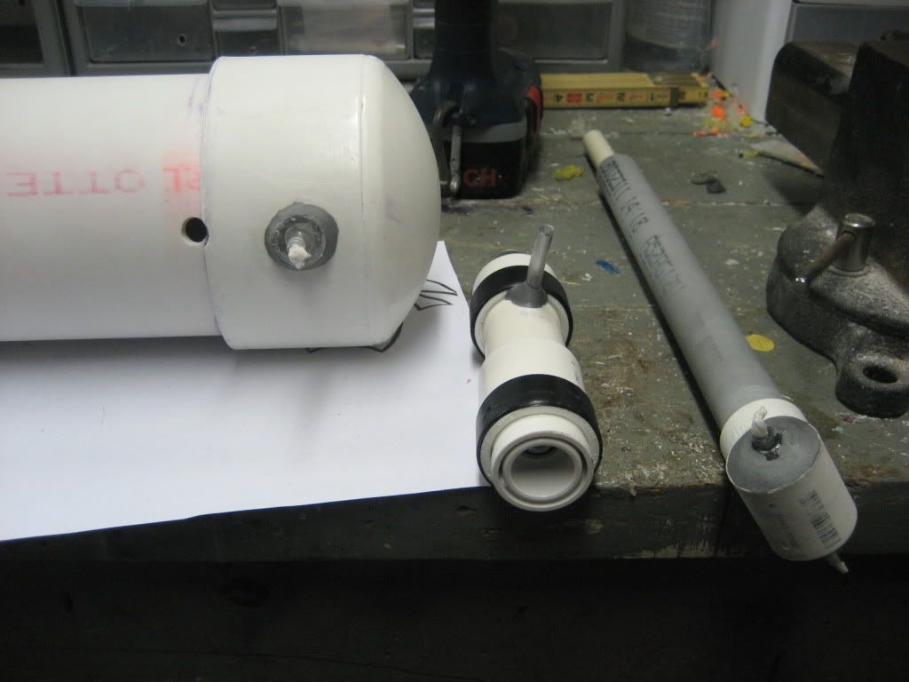
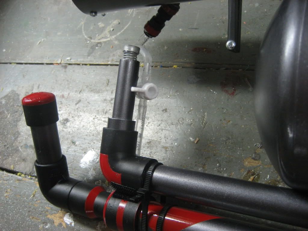
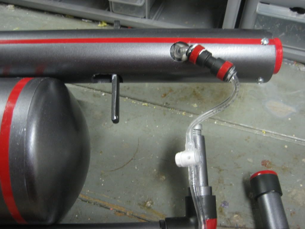
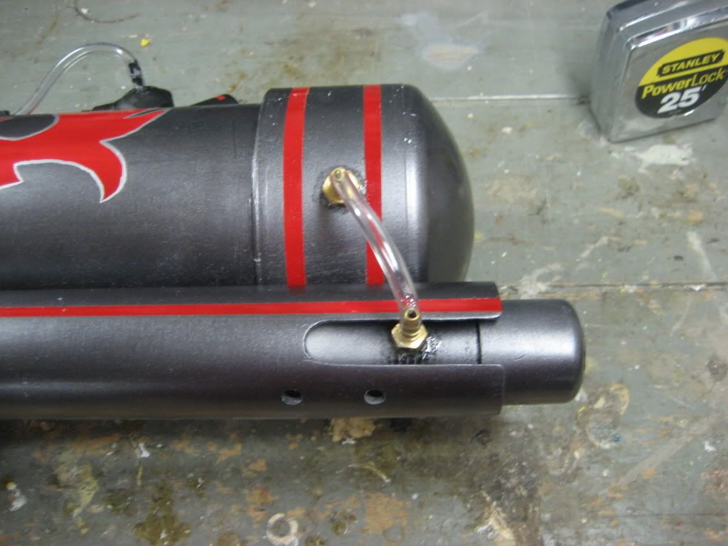
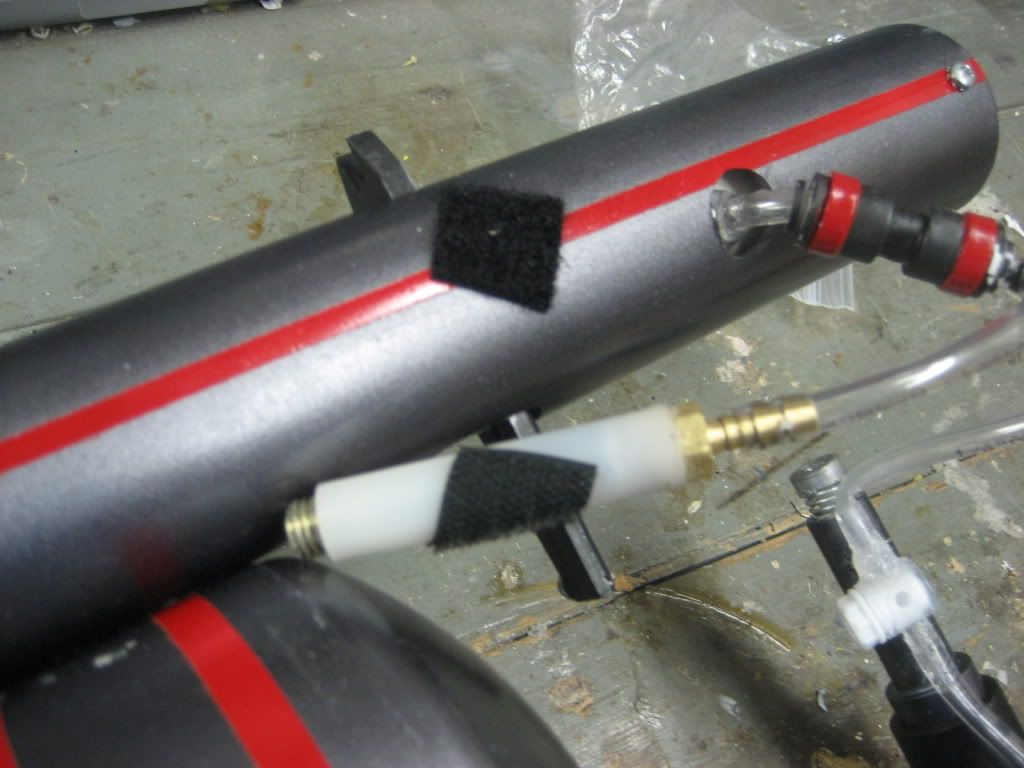
Forget the barb mentioned in the writeup. You want to end up with something like the picture below, so just drill a ¼” hole in the tank, goop 3” of your tubing in, and let it dry.
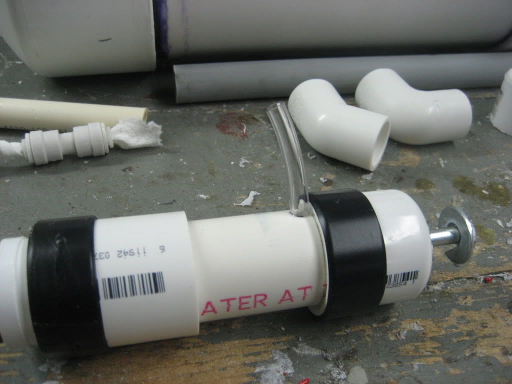
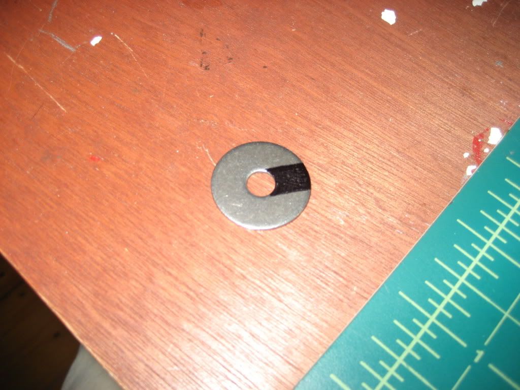
Lastly, you will want to glue a metal washer to the very end of the carriage bolt. The washer should look like this (the black part should be cut out so you can slip the washer over the shaft of the carriage bolt. This helps to increase the rate of air delivery because it enables the piston to be pulled farther over a shorter period of time.
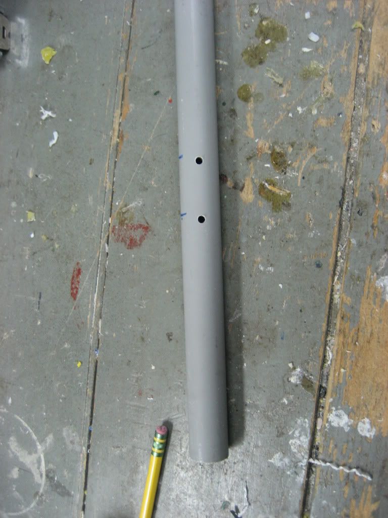
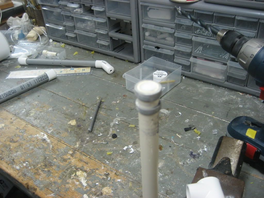
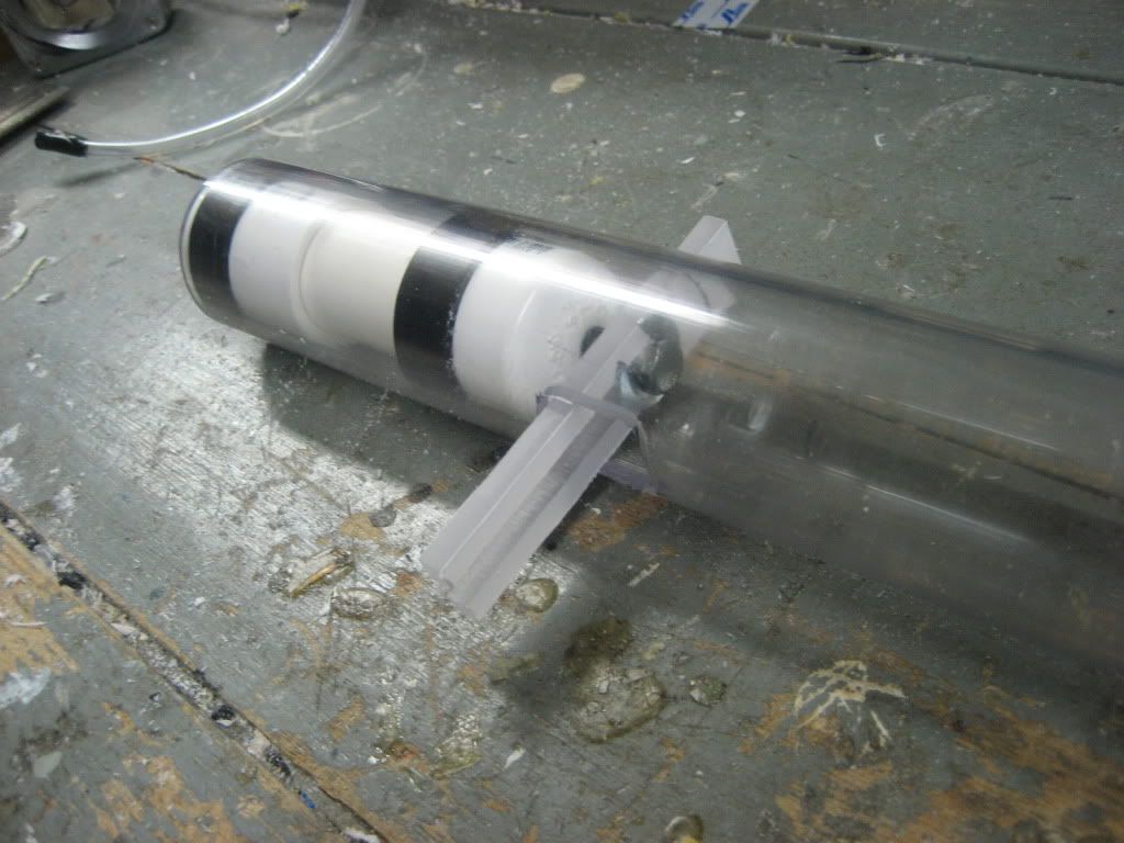
Next, wrap the PVAT in electrical tape until it fits snugly in the PETG. You want it to be snug, but also easy enough to take out when needed. Drill a hole 3 1/4” from the front of the tube at whatever angle you want the tubing to come out of the tank from. The hole needs to be large, so drill with a ½” bit and then sand it out to about the size of a penny.
Next, take your PETG tube and cut it down to 22.5” long. As shown in the picture, measure the given lengths from the FRONT end, and cut it out. The slot is about 7/8” in width. An easy way to measure this is to measure 7/8” onto a piece of paper and then wrap it around the tube.
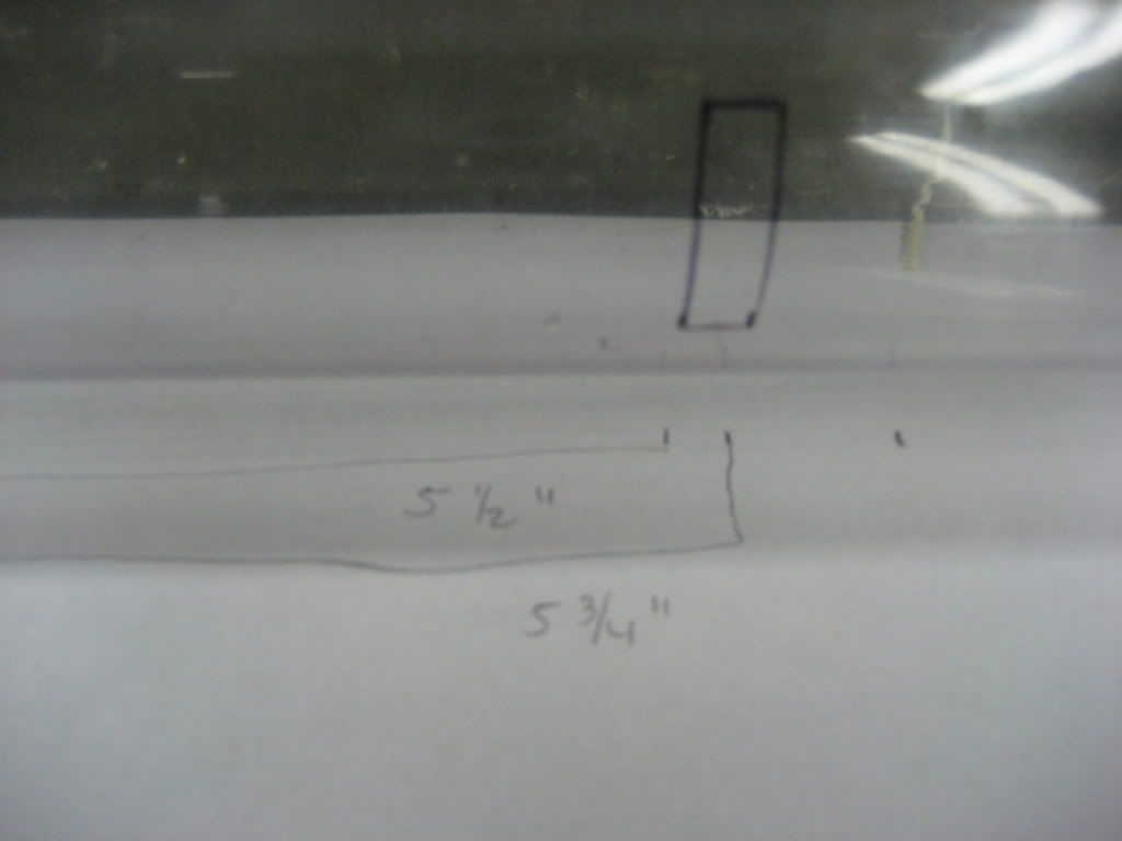
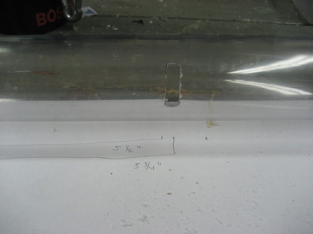
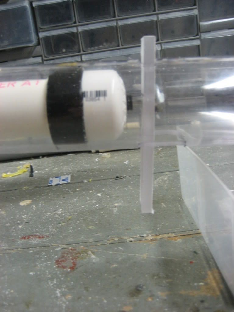
Check that your slot is the correct size by sliding the trigger into it. It should be a loose enough fit that the trigger can slide in and out easily, but it shouldn’t “rattle” around in the slot. This is the top of the tube now.
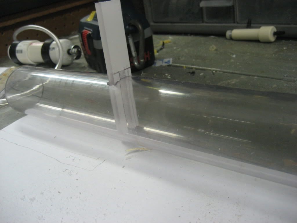
Next, mark out the given measurements on the UNDERSIDE of your tube, still at the same end as before. Cut this larger slot out.
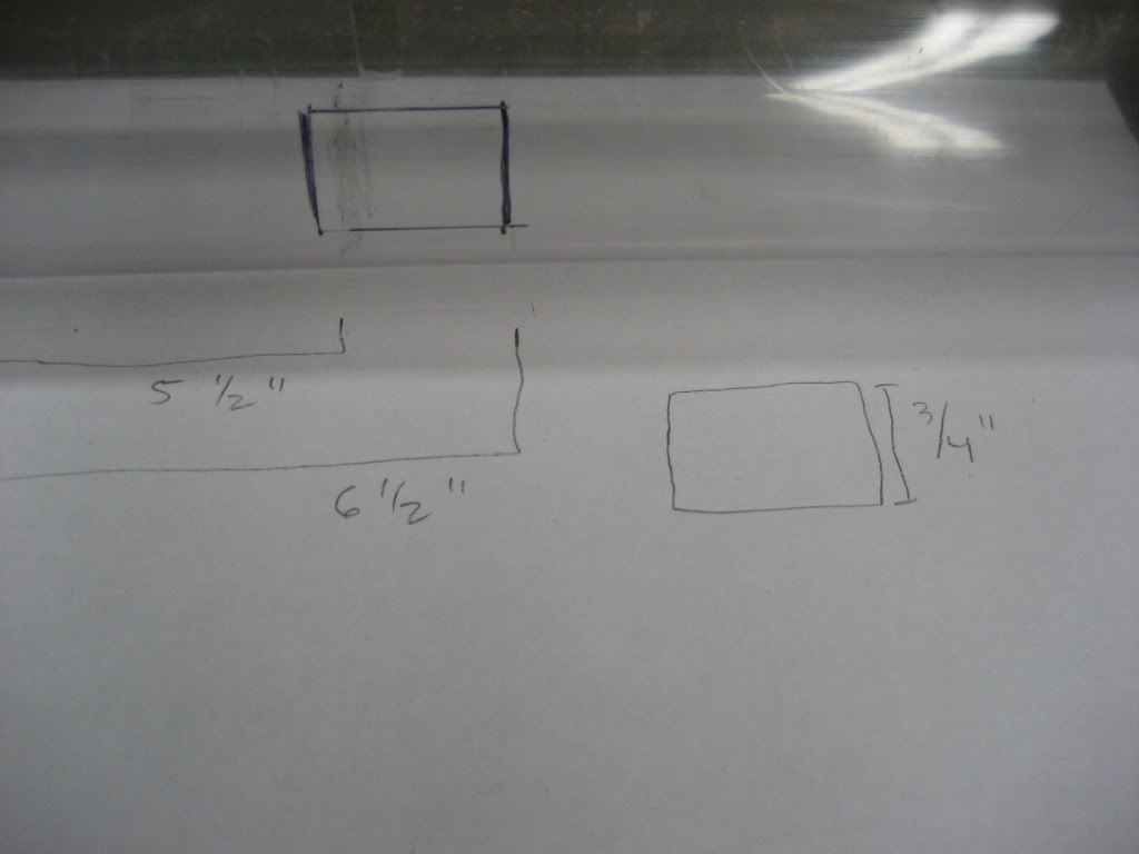
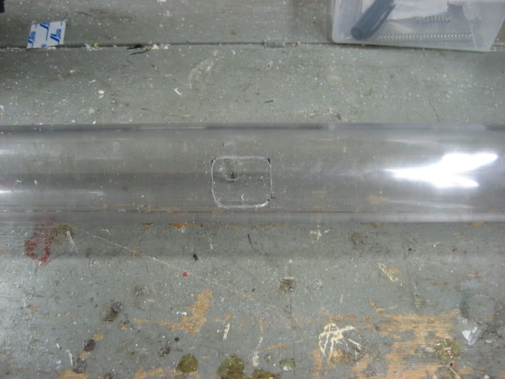
Slide the PVAT into the tube and test your trigger for fit. The two prongs should slide over the carriage bolt of the PVAT and then exit through the larger slot in the bottom.
------------------------------------------------------------------------------------------------------------------------------------------
Main Tank
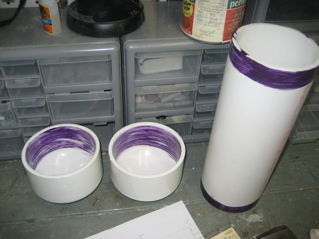
Take all of your 4” PVC components (endcaps and tube) and prime them with purple primer. Let that dry and then apply PVC cement. Slide the endcaps over the ends of the tube and let dry.
While that’s drying, insert your PVAT into the front of the tube and drill 4 7/64” holes equally spaced around the tube. Tap them with your tapping bit. Eventually, we will insert the ¼” 6-32 screws in these and tighten them down to keep the PVAT from sliding when the trigger is pulled.
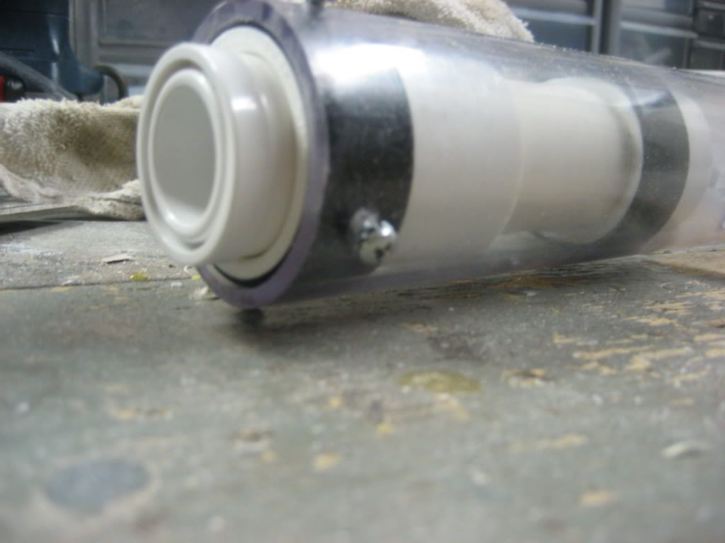
Next hot glue your tube to the 4” PVC tank so that the end of the tube and the end of the tank are square, or that they form a perpendicular line to the table.
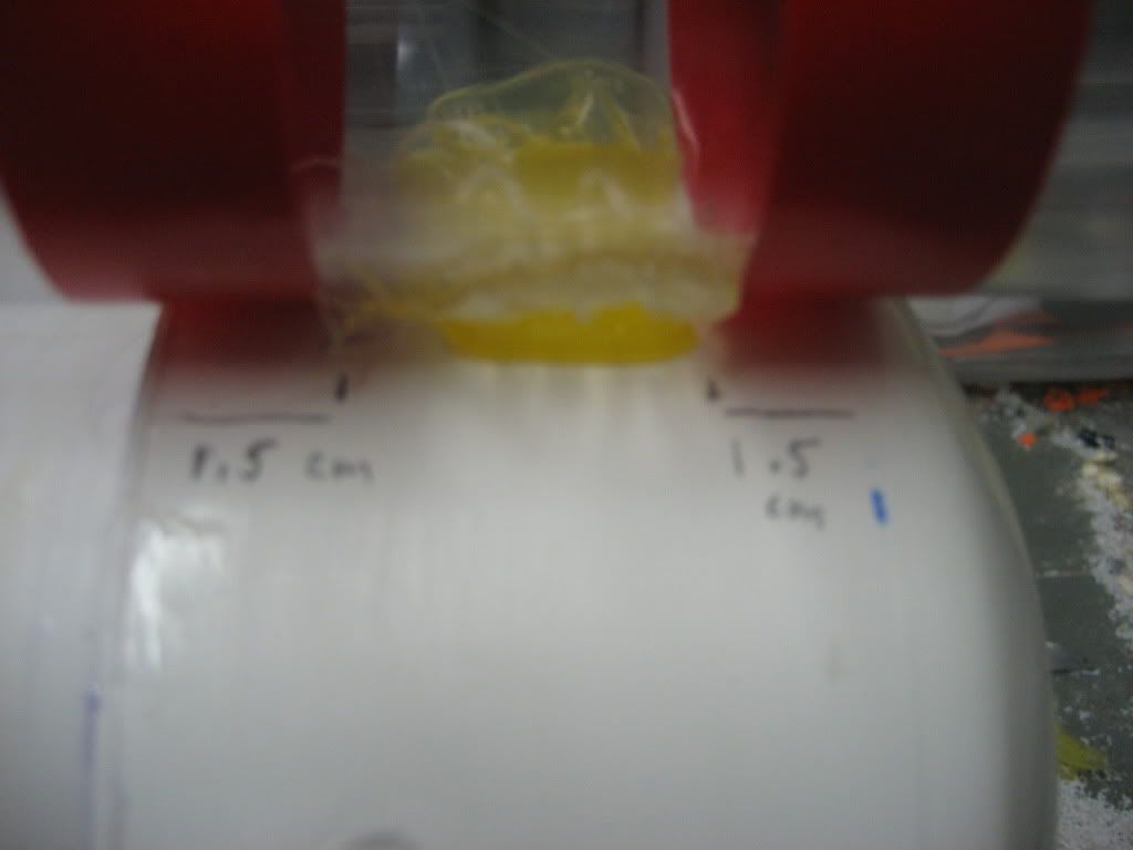
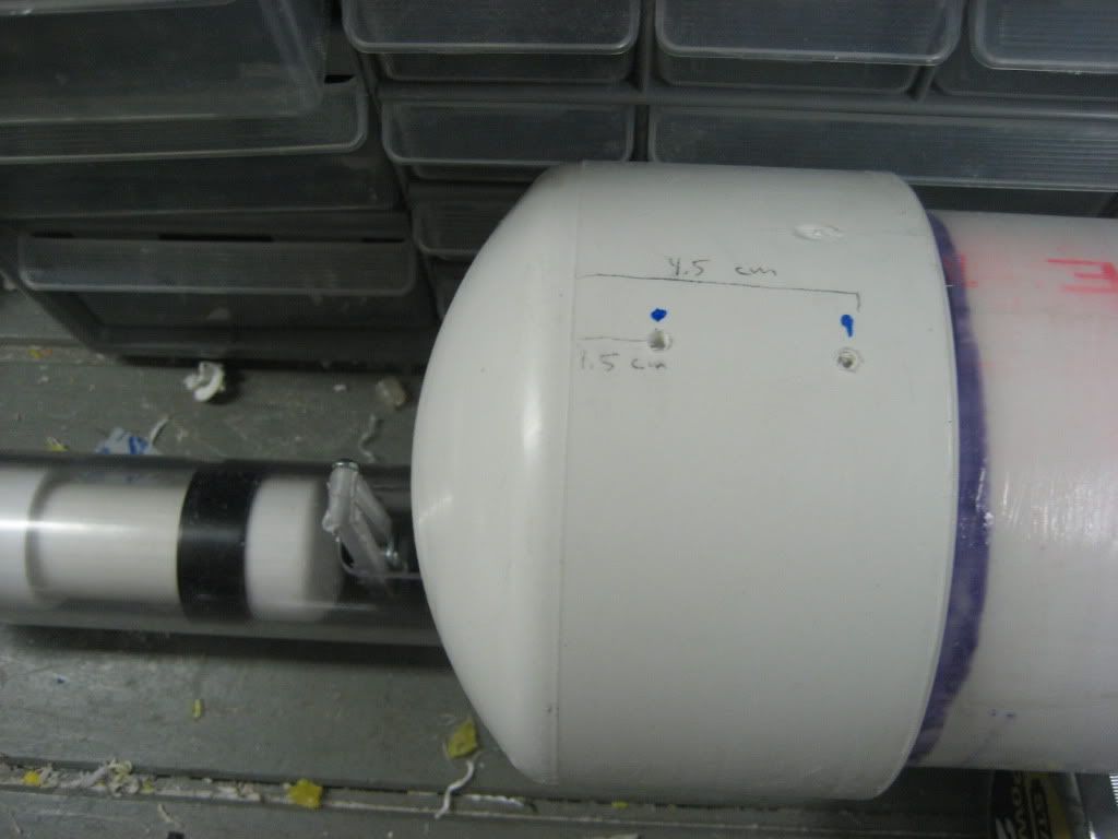
Now, set your drill bit in your drill chuck so that after drilling through the thickest part of the tube it still have about ¼” of clearance. On the front endcap, drill perpendicularly through the tube and ¼” into the PVC endcap in two places, shown below.
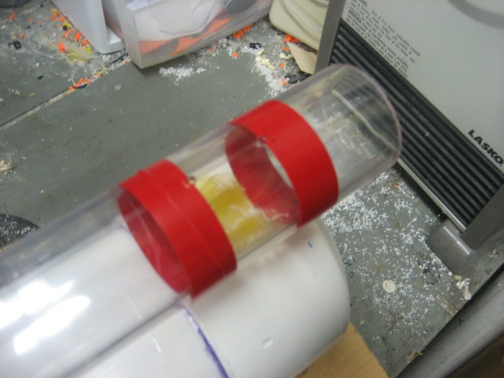
Widen the 4 top holes to 1/4”
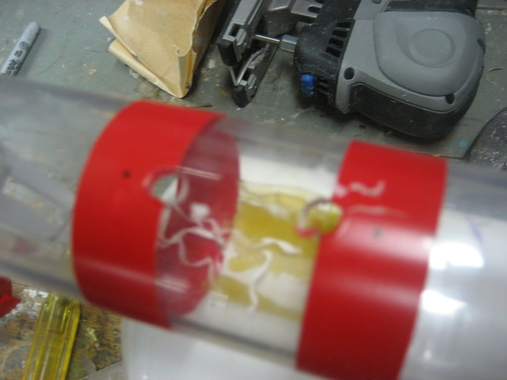
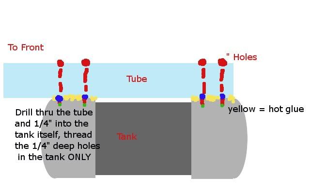
In the diagram, the 4 red dots at the top are 1/4” holes, the blue dots are 5/32” holes, and the green dots signify the original 7/64” holes. The hot glue is then removed (or left on if you want, it doesn’t matter)
------------------------------------------------------------------------------------------------------------------------------------------
Now insert the 4 3/8” long 6-32 thread screws. Make sure everything is tight and sturdy, and then disassemble the two parts.
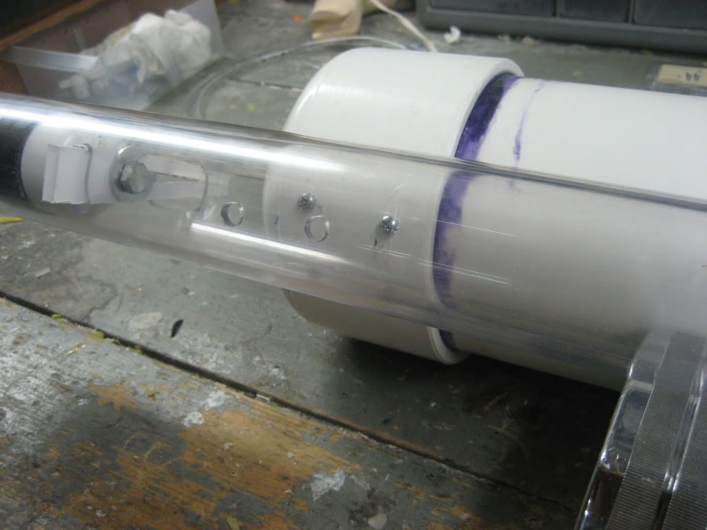
Mark and drill a hole about a ½” away from the back endcap. In the picture I drilled mine too close. It’s not a problem really, it just makes things easier later on if you drill it a little farther away.
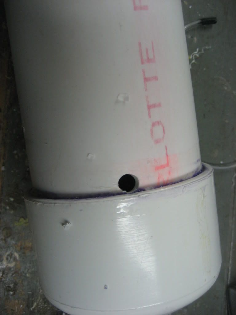
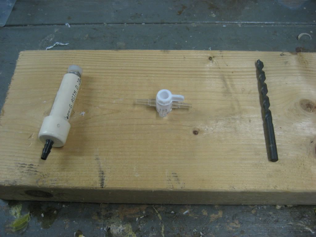
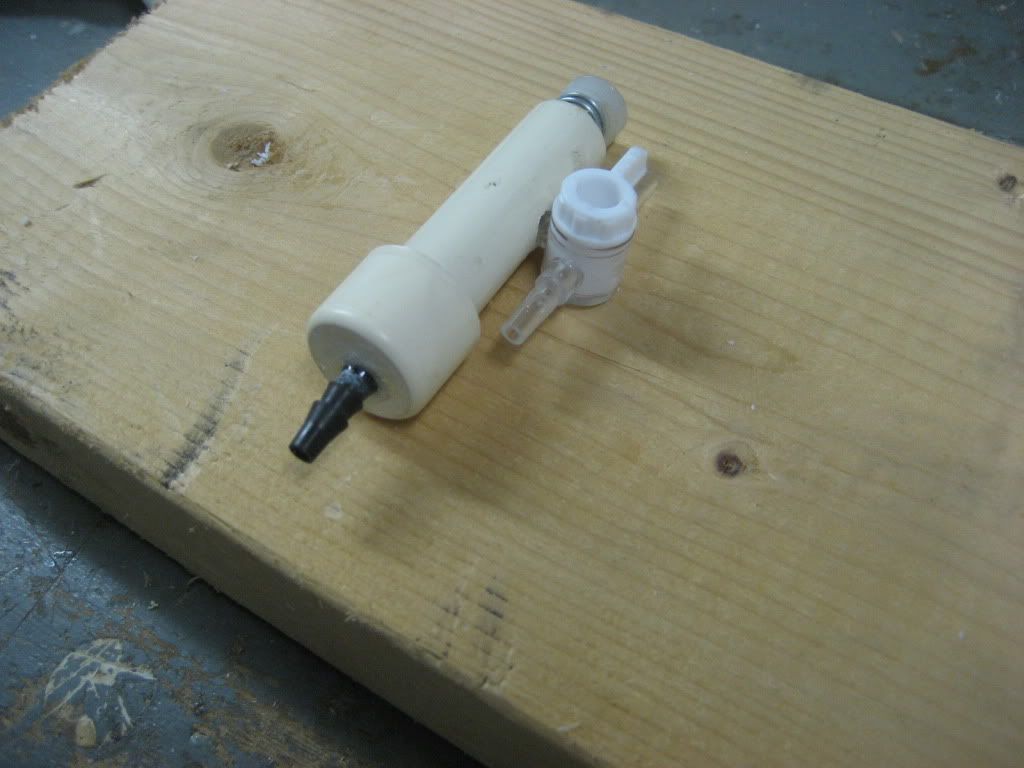
Here’s what you’ll need for this next step (that’s a dremel, a drill, a 3/16” drill bit, and a check valve):
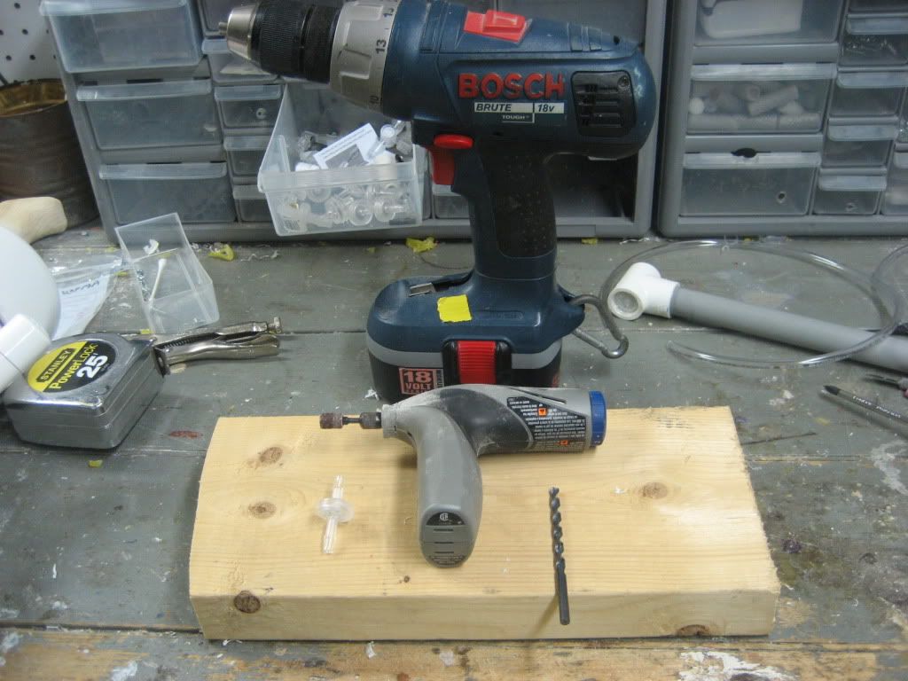
Measure an inch and a half from the hole you drilled earlier (This is the one on the bottom), and drill it out with the 3/16” drill bit.
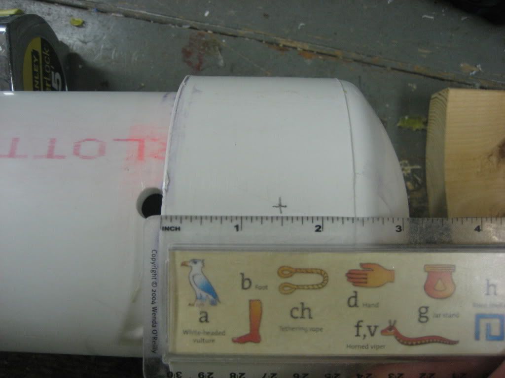
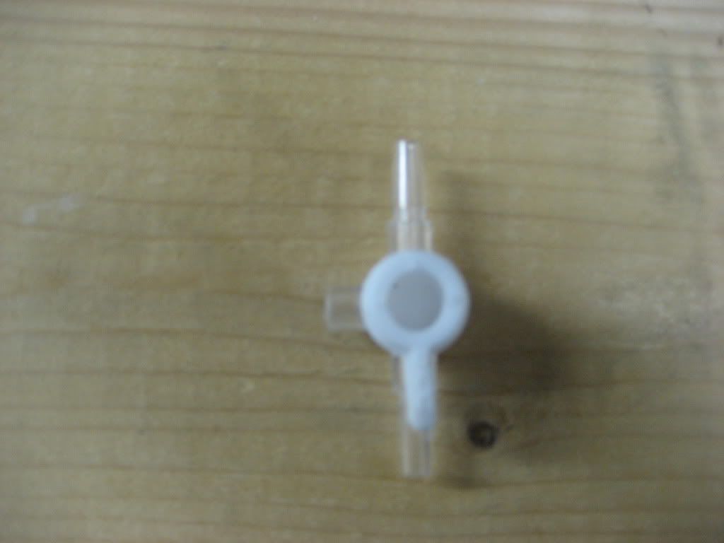
See how the check valve comes to a point on one side, but is flat on the other? That’s a built in arrow to signify which direction it will let air flow. Use the dremel to sand the flared portion of the nipple on the side that the arrow points to until it is flush with the “stem” of the nipple.
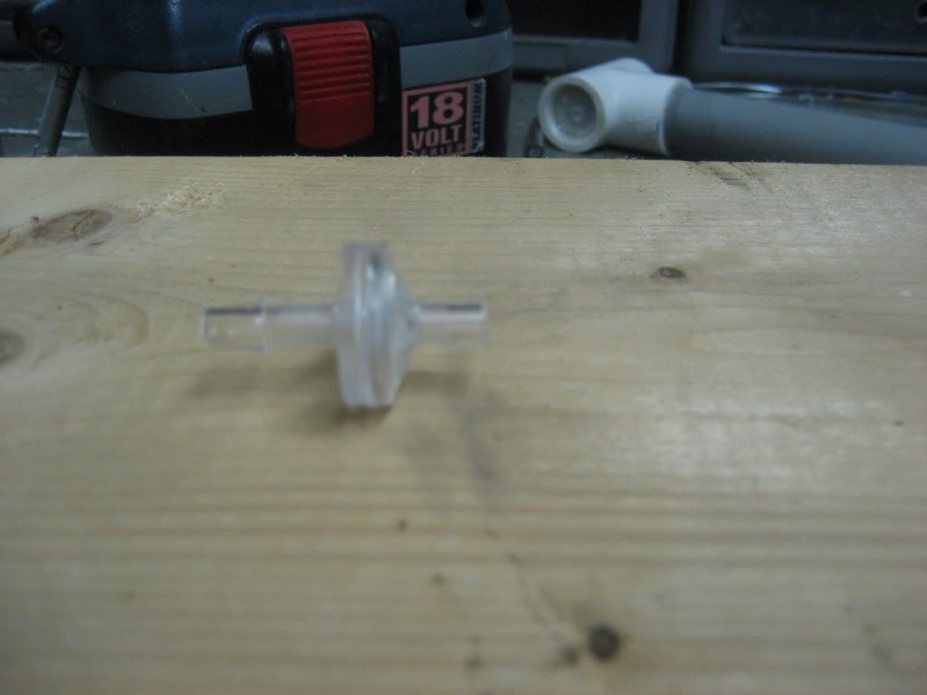
Test for fit, rough the stem with sandpaper, then superglue, solvent weld, goop, and epoxy putty it into the hole you drilled. (The picture doesn’t show the epoxy putty, but I promise I did it!)
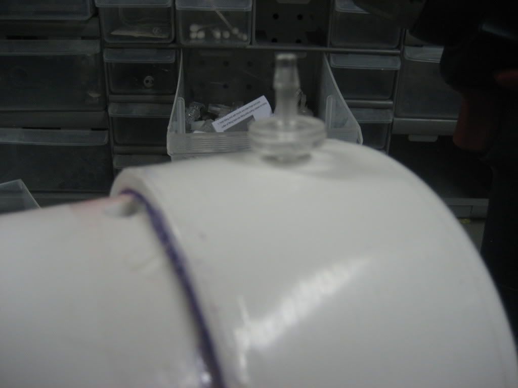
2nd tank
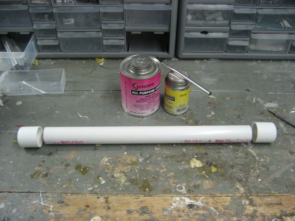
Moving on, assemble your PVC primer and cement, as well as your 1” PVC components. Prime solvent weld, cure, blah blah blah
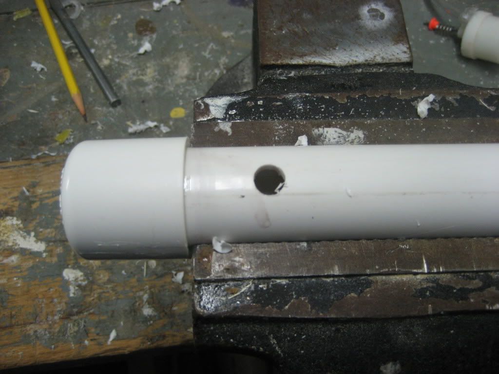
Drill a 3/8” hole 1” from the endcap
Pop the tank into the back end of the tube. Turn the tank so that the hole is at about 45 degree angle between the top of the tube and the tank.
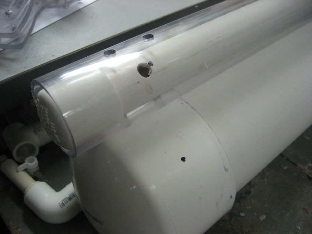
Mark the spot on the tube where the hole in the tank lies, and drill it out with a 1/2” bit, then extend the hole as shown in the picture
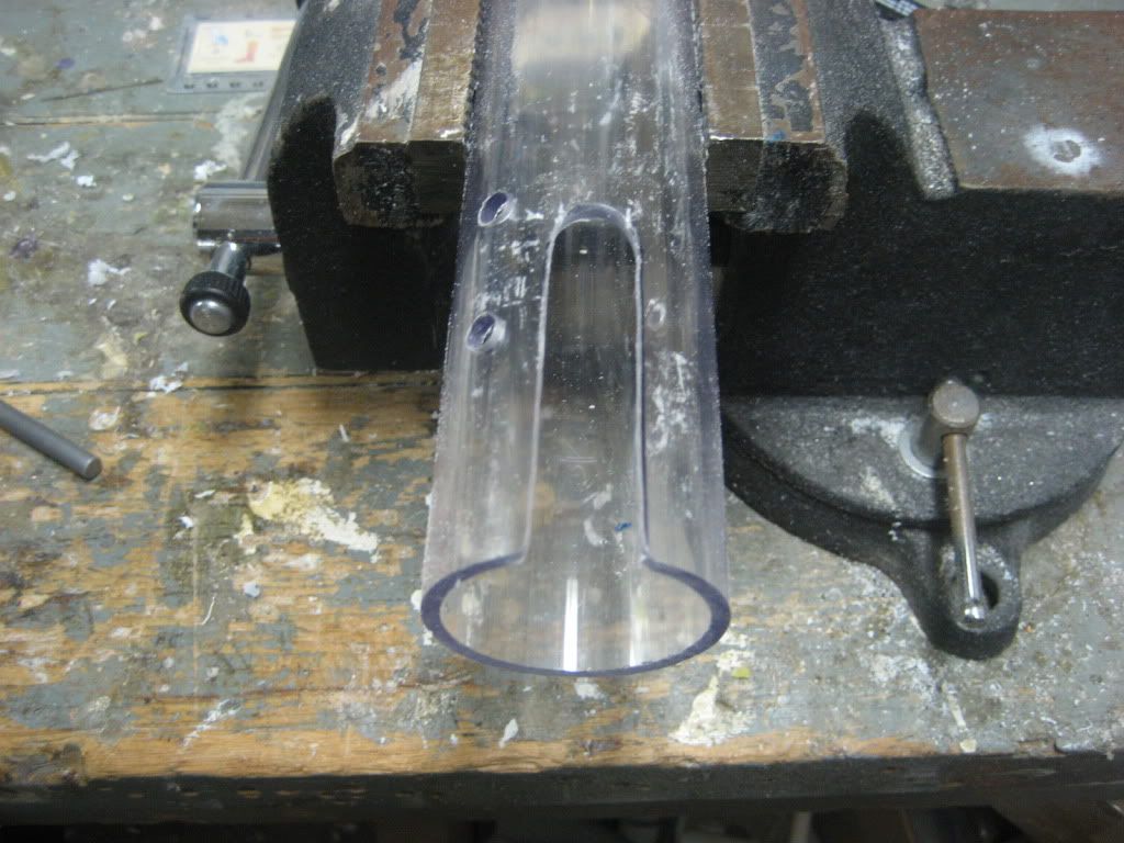
Lastly, and this is sort of a feel thing, drill a 3/8” hole on the side of the main tank you tilted the secondary tank towards

-----------------------------------------------------------------------
Edited by Whisper101, 12 August 2011 - 10:13 AM.


