extremely impressive list. Im just new to working with external hardware and parts such as those you listed, and am relatively new to the haven. Your and slugs work is extremely impressive, but its not exactly what i was going for.
Based on what you wrote, it sounds like
exactly what you want. You might not understand the system fully yet, but once you do, I bet you'll see the advantages of off-the-shelf valves and change your mind.
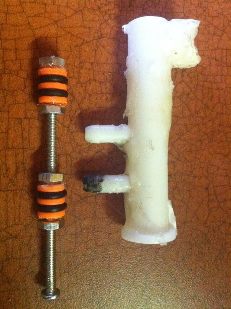
Im looking for a piston like motion similar to the last 2 links you sent. My current valve stroke and trigger stroke matches up exactly with the full piston stroke of my valve i have made, and it is compact enough to fit where i need it.
I doubt you couldn't adapt some off-the-shelf valve to work. You can't make the button be pressed at the end of the stroke? A small one like 62475K11 at McMaster-Carr could definitely fit, would seal perfectly, and would be easy to trigger.
Regardless, it's your project, so ultimately the choice is yours. I might get a little carried away with this subject, but I think it's justified as people spend way too much time trying to make valves.
Or at leas i thought I was untill Nerkum posted a youtube link of the clipard valve integrated into a magstrike operating a big salvo tank. nerkums cliffard valve He presented it on page 2 of Buffdaddys semi-auto salvo thread page 2 of Buffdaddys Semiauto Salvo. Now i'm just annoyed my nerfing budget is spent. This may be a good time for both of us to listen to Doom.
nerkum's video is a good example of what these valves can do.
If you're on a budget, I'd suggest trying eBay to find valves. You'll have to wait to find specific types of valves, but it's worthwhile. If you want Clippard valves, finding a local Clippard distributor (
see Clippard's website) is the best way to get those valves for cheap, however. The distributors seem to get a significant discount.