
 Find content

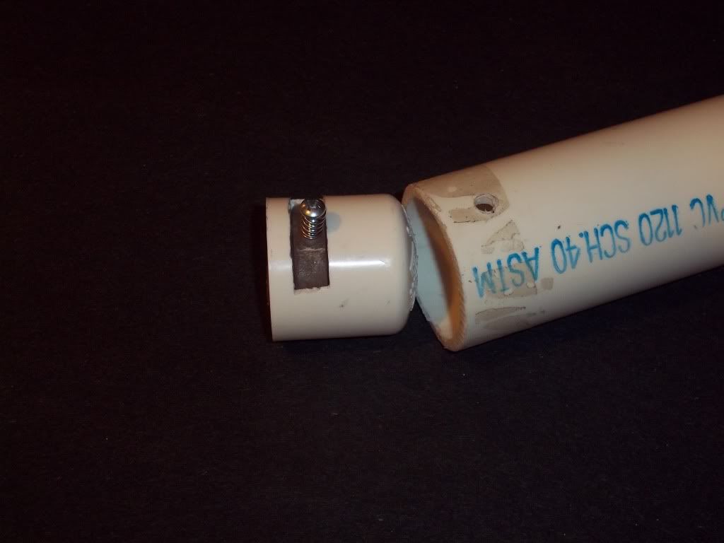
 Completely contained in the 3/4Tee
  7/16ths id shaft collar (drilled out to 1/2in)
 Upcoming pump action I'm workin on. If you guys want a write up let me know. Feel free to ask any questions and or comments.......Later, Mod
29 November 2010 - 01:54 AM
Completely contained in the 3/4Tee 7/16ths id shaft collar (drilled out to 1/2in)Upcoming pump action I'm workin on. If you guys want a write up let me know. Feel free to ask any questions and or comments.......Later, Mod
19 October 2010 - 11:08 PM
12 October 2007 - 02:30 PM
 Cool, Later Mod
Hey Im having problems resizing the image. I've checked out the info posted on it and don't understand when I grab and drag to size....any help is greatly apperciated.Hey, Check it......
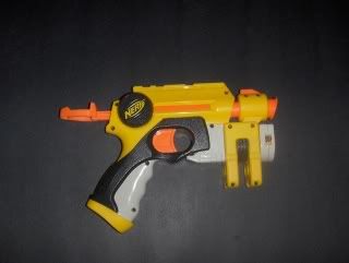
Some other changes are its a small hole (screw holes) B mold with an old style plunger head. Also there is some kind of small capacitor or something on wiring between trigger pressure switch and batteries. Best part is the new battery cap with a screw that isn't as likely to strip out. What do you guys think? and are they around your area yet?

