Jump to content


Carbon

Member Since 26 Jan 2006
Offline Last Active Jul 20 2023 11:13 AM

Topics I've Started

The SNAP-10 Slamfire

28 May 2012 - 09:12 PM

At Cataclysm on Saturday, Langley told me about a concept he had for a blaster: a slamfire-only SNAP, where the trigger was tripped at the very end of the priming stroke. We talked about issues with the design, and I wondered about using an extension spring with it, like the Revolution. This blaster is the result of that conversation. Thanks, Langley!

Note: this is a proof of concept, with refinements to come later. So, let's get this turkey roasting, shall we?

Posted Image
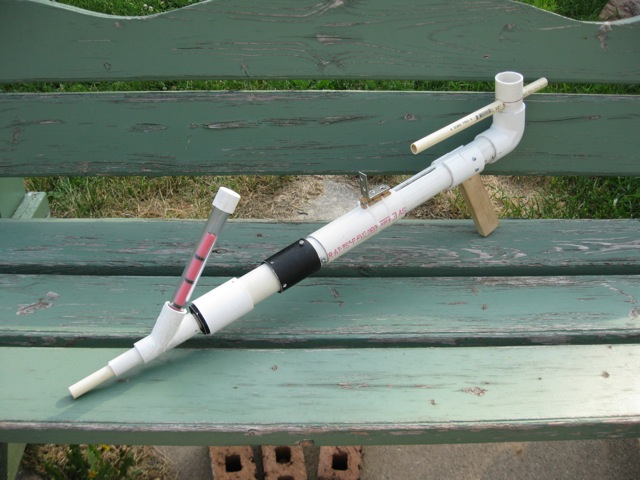
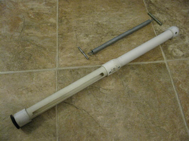
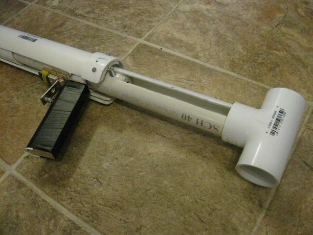
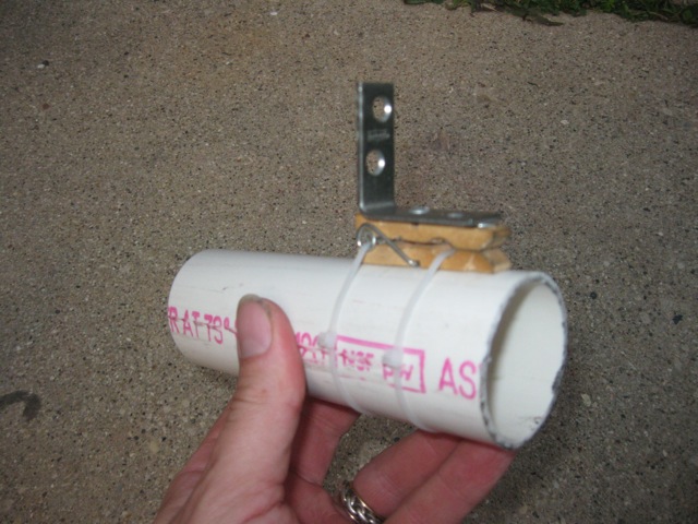
A glamour shot of what may be the least glamourous SNAP ever.


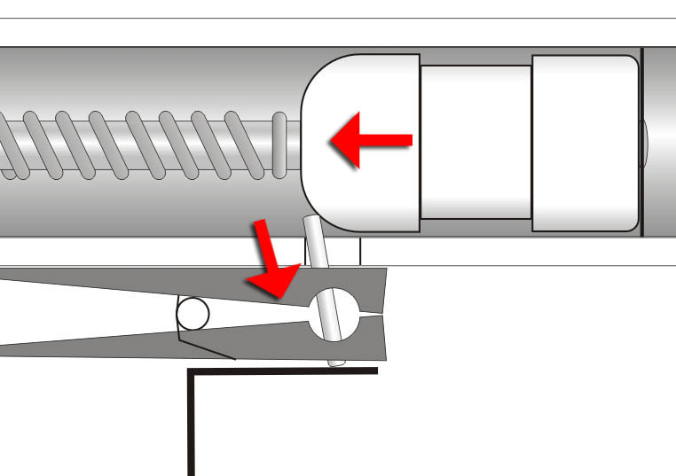
Functionally, it's very similar to the SNAP/Revolution, but has a few differences as far as operation. Here's a side-on view:
Posted Image

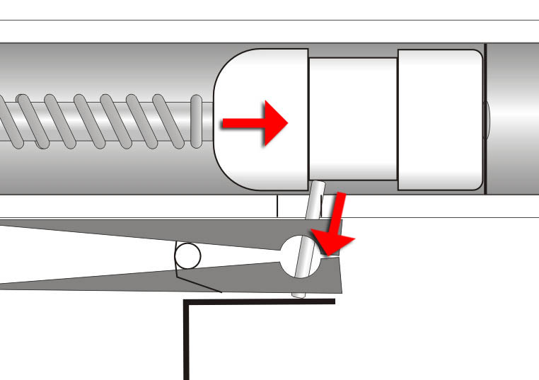
And now a version with 87% more exploded view:
Posted Image

Now then, on to the parts...
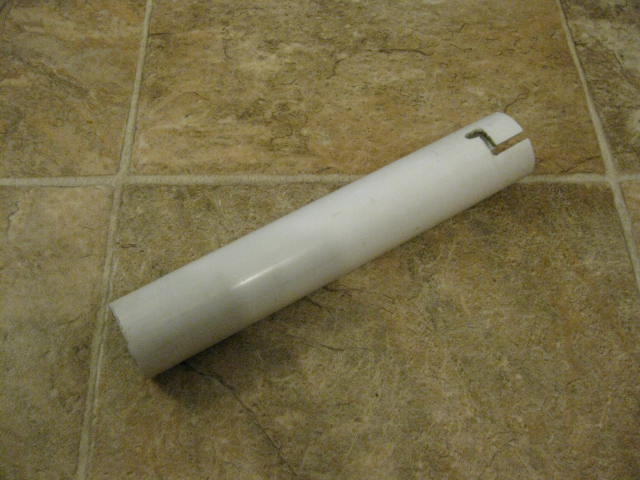
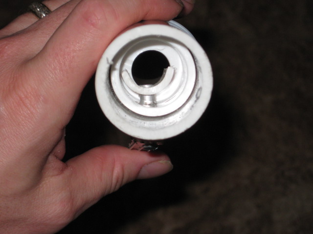
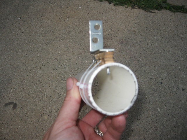
The Receiver:
Posted Image

You can see the slot in the top where the firing pin slides. The slots in the front are for the forward spring stop in the plunger. These slots are in the plunger tube on the SNAP/Revolution. The triggering arm is what actuates the trigger on the trigger slide. It's ugly, but functional (I built it using the first three scraps I could find (the arm is 1/2" CPVC, shoved through a hole in a chunk of 1.25" PVC, in a 1.25" elbow).
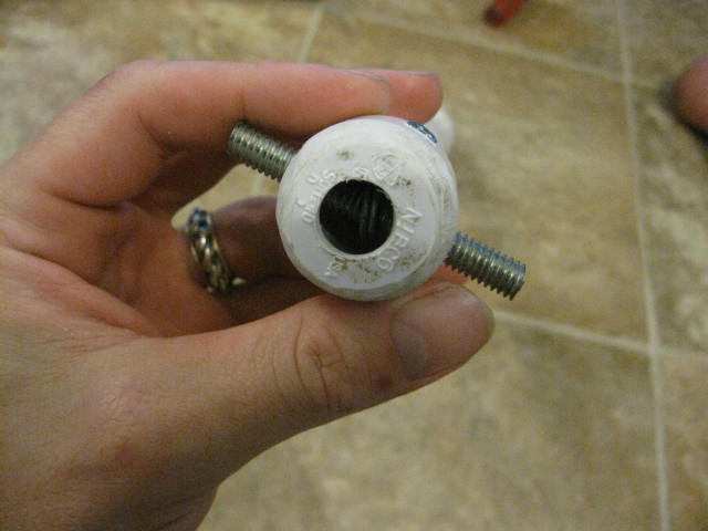
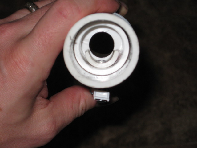
The Plunger:
Posted Image

Here's the biggest difference from the SNAP-9: The catchface is on the end of the plunger (like the SNAP-PAC and the SNAP-8), and the spring is tensioned inside of the plunger tube (as opposed to being hung from the receiver on one end, and the plunger tube on the other end).
Posted Image

The plunger assembly then just drops into the receiver.
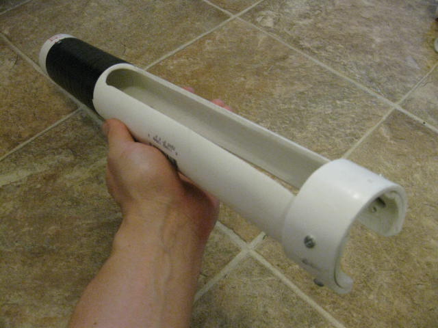
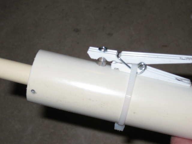
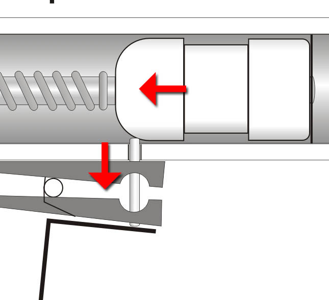
The Charging Slide:
Posted Image
Posted Image

The charging slide is made of 1.5" thinwall, which slides perfectly over 1.25" PVC (thanks to SomethingNerfey for hooking me up!). I was a little surprised that it has enough wall thickness to support a CPT directly, but hey. I'm not going ot argue with success. It's a typical clothespin trigger. The nail rides in the slot on the receiver. Push it forward, and the CPT will engage the rear of the plunger tube. Pull the charging slide back, and the plunger goes along for the ride. When it meets the triggering arm:
Posted Image
Posted Image
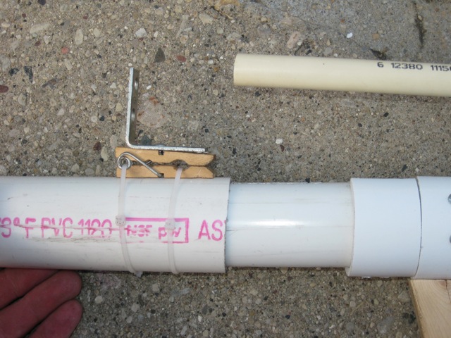
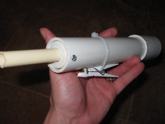
The extra bit in front of the handle clip is there as a travel stop, so the slide can't over-extend and pop out the nail. Future versions could just have a longer charging slide.

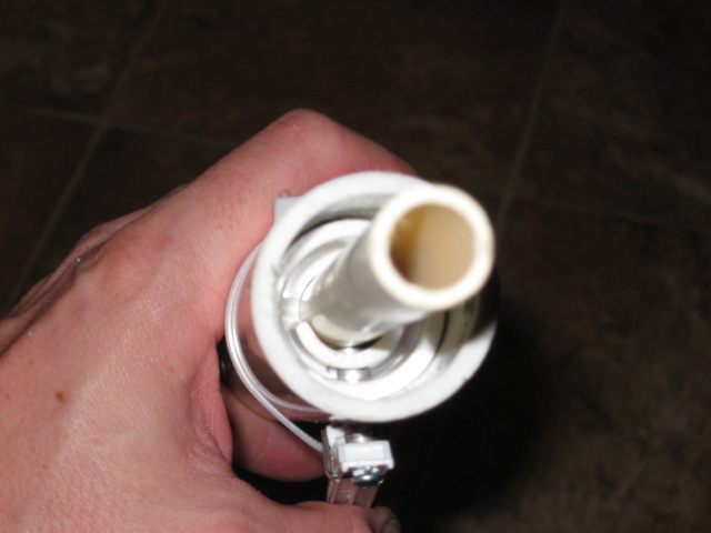
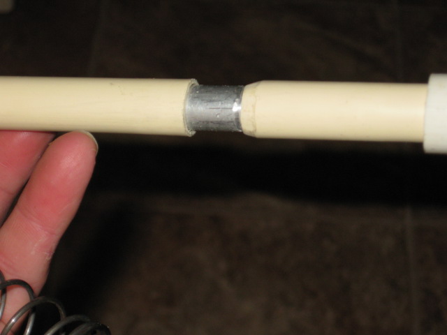
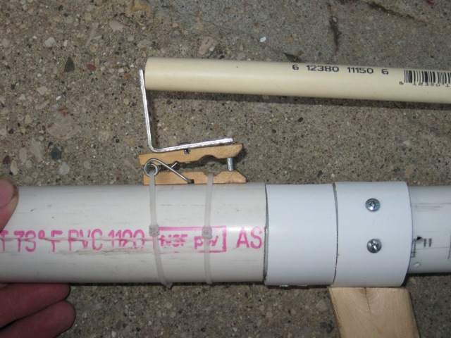
The Hopper, Barrel & Plunger Tube:
Posted Image
Not much to be said here. The plunger tube currently attaches with a screw, but could also use the SNAP/Rev tool-less plunger tube clip method.

Assembly:
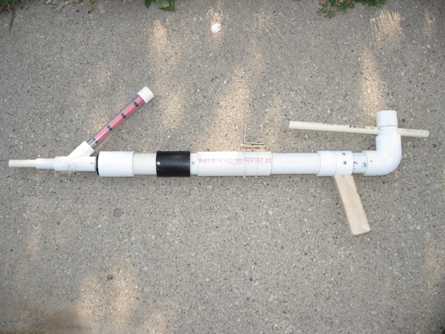
It breaks down and assembles quite easily:
1. Slide the plunger tube into the receiver.
2. Lift the CPT, and slide it onto the receiver until the nail clicks into the top slot on the receiver.
3. Press the plunger tube/barrel assembly into place, and screw down.

Questions:

Q: So, what kind of range does it get?
A: For a proof of concept, Far Enough. I didn't take any accurate measurements, and it's hard to fire a slamfire flat. Estimating, I was spamming darts about 60 feet.

Q: How fast does it fire?
A: I can empty the five shot hopper in under three seconds, arrived at by a highly scientific method of counting "one-one thousand, two-one thousand"...

Q: How strong is that spring?
A: Not exactly sure. The spring in the SNAP/Rev is about 14 pounds, and this one is far weaker. I'd guess...8 pounds?

Q: Isn't a five shot hopper sorta useless for a slamfire gun?
A: This is a proof of concept. Future builds will use a larger spring, will be able to use a larger hopper, and will probably get better range.

Q: That triggering arm doesn't look very stable.
A: The current shape was built for easy adjustments and tuning. Even so, I put a few hundred darts through it this afternoon, and it never shifted on me.

Q: That thing's really ugly, like it got hit in the head with a really ugly thing.
A: She may not look like much, but she's got it where it counts, kid.

Heavy Metal Nerf

20 May 2012 - 10:49 PM

Found this project tonight. If you were making a homemade Tesla gun, what kind of case would you make for it?

Why, a cast aluminum Nerf shell, of course.


This photo set is from a larger overview of the building of a portable Tesla gun (which doesn't seem like the sort of thing that should get posted on NH)...but if you live in the Seattle area, apparently you can take metal casting classes with the guy who did the casting of the Nerf gun.

The SNAP/Revolution

19 June 2011 - 10:01 PM

After thinking on this design for the past year, I finally decided to do something about it, especially since it meant I could war test it at SPANO. Here's the tuned prototype:

Posted Image

As I said in the photo thread, this is a SNAP, but with very different internals. Let's explode that sumbitch:
Posted Image

And now: the ridiculously photo-heavy writeup.

Design Process:
The idea for this blaster came about after MANO last September. I had just finished the SNAP-8, my take on an internally sprung PAC-style blaster. Aside from mechanical issues, I just ended up not liking it. What keeps drawing me back to the PAC is how smooth the priming action is, with almost no friction. Compression spring systems have far more friction points, so the priming action isn't as smooth. So I decided that I needed to build a blaster using extension springs. (For those keeping track, yeah, I never posted the SNAP-8. There's a reason for that.)

Rather than run the spring external to the plunger tube, I decided to run the spring down the middle, with a coupler sanded to the traditional ramp and catchface. This was mostly due to the length of an extension spring system. It didn't take me much figuring before the benefits became pretty clear:

• Greatly reduced plunger friction means a weaker spring can be used. Easier to prime, equal performance.
• Safety: when the system is primed, the spring is trying to pull the blaster together, rather than blow it apart.
• Making a dry-fireable system would be trivial, as the spring itself limits the range of travel.
• Having the spring inside the plunger tube means no more snagging the nail on the spring.
• The nail rests on the plunger tube for the entire action of priming. Because of this, it doesn't matter how long the nail is. Goodbye, fussy nail trimming.

The design of this blaster ended up with another benefit: it can be almost completely torn down without tools. Future updates to this design will be able to be completely taken apart without tools. It should also be pretty simple to make this dry-fireable, as the spring itself limits travel. It pretty much is dry-firable right now, as the plunger head doesn't impact the front bushing.

So, let's look at the parts a little closer:
Posted Image

Materials used:

This is a general list, as this isn't a step-by-step writeup. Your mileage may vary.

Blaster Body:
1.25" Sched 40 PVC
1.25" couplers
1.25" -> 1.5" bushing
1" -> .5" bushing
1.25" Tee
2" Sched 40 PVC

Plunger:
.75" thinwall PVC
.75" Sched 40 PVC
.75" coupler
.75" endcaps
Threaded rod, or any manner of sturdy metal
9.75" x .5", .062 extension spring (available at Menards)

Basic SNAP parts:
Clothespin trigger
Handle (this handle is my basic firring strip/PVC clip method)
Endcap plunger seal

Receiver:
Posted Image

This is pretty much standard SNAP: basic CPT, usual handle. I cut the slot all the way through the back for ease of assembly (decided upon during the build process). We'll get into how this is put together later on. I chose an arbitrary draw length of around 6" (which is reasonable for my ~10" extension spring).

Plunger:
Posted Image

Here's what makes it different. The catchface, instead of being right by the plunger head or at the end of the rod, is situated in the middle. Instead of an endcap, it's a standard 3/4" coupler. I took a few minutes to slope the rear of it to create the ramp for the nail. Benefit of this design: the ramp can be very gradual, making for smooth priming action. Also, the nail itself is limited in its travel by the rear of the plunger tube. In other words, there is no nail "tuning" needed for this style of SNAP. A too long nail which wouldn't work in a standard SNAP will just rest on the rear of the plunger tube, and glide until the catch.

The rear of the plunger is .75" sched 40 PVC. The front is .75" thinwall, for easy slot cutting and light weight. The plunger head doesn't impact a bushing, so structural integrity is't really needed. The slot os also not for any accuracy, it's more for "get the hell out of the way of the spring".

The plunger needs some manner of securing, to keep it from pulling apart during priming (thinwall doesn't hold in a coupler that securely, and grinding off the end of the coupler means the sched 40 PVC doesn't hold that well, either. I'm currently using two small screws. The hole in the coupler is wide enough to let the head all the way through, and it screws into the tube. It's enough to pin the tube together. I'm going to use adhesive on later builds.

The spring is from Menards. 9.75"x.5", .062 wire. The spring at rest sits in the solid tubing on the right, pinned by the thicker bolt through the endcap. The thinner bolt holds the loop at the other end. The slotted length allows the plunger to move back while the spring increases in length.

I did a post-war disassembly to check on the durability of this design. As it stands right now, it seems that reinforcement won't be necessary. This follows, as the spring in this blaster is a little weaker than the springs I used for a basic SNAP-1, which never needed reinforcement.

Plunger tube:
Posted Image

Yeah, it's a tube. The cuts allow it to be snapped on to the front spring rest (the thinner bolt). I need to work on this section a little, as it can occasionally wiggle its way off. Ideally, this part should also be under spring tension, so the pull of the spring itself can hold the entire blaster together.

Priming shroud:
Posted Image

What you'd expect. It's actually a couple pieces taped together, because I built this gun out of scraps. The top slot doesn't need to be as long as it is, but it helps keep weight down a little. The bottom slot is a little wide, so it's being guided by the screws that hold the handle on (screws will be replaced by epoxy, and strips of PVC for guides.) There's a sanded out ring of 1.25" coupler in front to keep the thing from wobbling. It just pushes the bolt in the rear, pushing back the plunger.

Putting it together:
1. Drop the spring into the plunger tube and pin it with the large bolt. When all is said and done, you'll want to keep the spring centered on the bolt.
Posted Image

2. Slide the plunger into the receiver.
Posted Image

3. The spring is under a bit of preload, so reach in with a screwdriver and lift it up. Hold it in place with the screwdriver. Then, slide the bolt under it and slide out the screwdriver.
Posted Image
Posted Image
Posted Image

4. Pop on the plunger tube.
Posted Image
Posted Image
And stick the rubber washer endcap on the end. The seal style I'm using is identical to the SNAP-1.
Posted Image

5. To allow the Tee for the stock to slide on, I used a 1"->.5" bushing wrapped in tape, then shoved on the tee.
Posted Image
Posted Image

Final thoughts:
I'm very pleased with how this blaster turned out. I used it the entire day on Saturday, and had no failures. The spring popped loose once when someone else dry fired it repeatedly, but restringing it was easy to do in the field. Ranges were comparable to any pump action SNAP on the field, with an easy priming action. Refinements are needed, but I have my new go-to primary.

Things to do:
• Reinforce the plunger catch
Yeah, I said it didn't need it, but I want to make this thing bombroof. I'll test out JSB's suggestion, as well.
• Attach the handle with epoxy
Currently, there are screws holding it on that have to be backed out a bit to remove the plunger. I'm going to trim those off and use epoxy to permanently attach the handle (and possible add a better, slightly more shapely handle).
• Fix the plunger tube attachment method.
It has a bad habit of wiggling off. I want to find a method that will hold it securely, but not use screws.

The Clothespin Trigger Mk2

17 October 2010 - 11:25 PM

The clothespin trigger is really simple to make, but it has its issues. Mainly, adjusting the plunger head ramp and nail length takes trial and error, and tuning to get it just right. Also, since the catch is before the spring stop, there can be problems with the nail hooking on the spring.

Things finally clicked for me when I saw Stark's fantastic RainBow. Needless to say, this catch wouldn't have happened without the Rainbow and the Minnesota crew. Major props, guys.

The goals with a CPT improvement was to get rid of the issues with nail length tuning and spring size issues, while making sure it could still be built with basic hand tools. Check and check. Here's how it currently looks.

The trigger installed:
Posted Image

Main deviation from the Rainbow catch is that it uses the clothespin to push up and keep the catch caught (whereas in the Rainbow, the push up fires the blaster). This keeps the motion the same as the old CPT. (EDIT: Yeah, the clothespin is backwards. I used a short piece of PVC for the test install, so it wouldn't fit the other way. The clothespin can go in either direction.)

Held in place by one screw and the firing pin:
Posted Image

The view of the inner workings, with the rear endcap removed:
Posted Image

The aluminum tube is screwed into the clothespin. The actual catch is made of 1/2" PVC with a hole to accept the aluminum tube. Currently, it's just pressed together, and it seems to hold fine. Later refinements will probably used threaded spacers from the hardware store.

The rear endcap keeps the plunger rod centered in endcap holes, and keeps the plunger rod catch from hooking on the front endcap hole. The front hole needs to be a bit looser than the back, to make sure that the plunger rod notch doesn't hook on the front hole.

Here's how the plunger rod is set up:
Posted Image

1/2" Aluminum tube nests in 1/2" CPVC with some convincing. Once again, a stronger spring may need a retaining pin, but currently, it's not going anywhere. I beveled the front edge to allow the plunger to keep moving if I overdraw. Otherwise, the plunger draw would stop suddenly when the draw reached the front of the catch indent.

Another view of the catch, with no plunger rod in place:
Posted Image
Posted Image

This is mainly a proof of concept, built with scraps around my workshop. Improvements can be made in the form of ease of assembly. Mainly, I'd like to see the aluminum tube be threaded into the catch, as opposed to just pressed in place. Still, even with this assembly, it built just fine, and required none of the tuning of a normal SNAP catch. The only slightly critical part is placement of the hole for the catch rod: it needs to be placed so the catchface is sliding up and down against the back of the endcap, so the force of the spring can be transferred to the front endcap. Otherwise, the catchpin will tilt, and cause similar issues to a standard CPT where the hole is too big. Then again, this system is probably a bit more tolerant of issues like that, since the catchface is in constant contact with the plunger rod. More building is needed to find out.

The Clothespin Trigger

24 September 2010 - 10:29 PM

I’ve talked to a lot of people, and seen a lot of SNAPs at wars and in pictures…and I know that getting the clothespin trigger (hereafter referred to as CPT) to work correctly is something that can take a bit of doing. From what I’ve seen, though, most problems with a clothespin trigger can be tracked down to one spot: the hole in the plunger tube.

For the lazy, here’s a TL:DR. If you’re having problems with a clothespin trigger, the hole in the plunger tube is probably too big.

For the reasons why, read on.

First, some explanations about how it works, and what the parts do, starting with that most visible part.

First things first: the clothespin does absolutely no work in resisting the force of the plunger spring. I’ve heard some comments from people about how their clothespin is “too wimpy” and how it can’t stand up to the force of the spring, or seen SNAPs with rubber bands around the clothespin to keep it shut. Both are symptoms of the same problem….and the only reason to put a rubber band on a CPT is if you like a stiffer trigger pull.

The clothespin serves as a lever with a return spring to lift the nail, and then put it back in place: that’s all. The work of resisting the plunger spring is done by the nail and the hole.

(A note about the hole in the clothespin: that actually needs to be a fair bit larger than the nail. We want the nail to slide straight up and down in the hole, but the clothespin moves on a pivot. Since its motion is circular, the hole needs to be bigger to allow for a bit of wiggle. After all, the clothespin is just lifting the nail. The spring is putting the nail back into place. All that can be done by the nail head, and doesn't need any contact on the shaft of the nail...so make the hole in the clothespin loose.)

For all practical purposes, a plunger spring cannot shear through metal. That’s why most any nail works in a SNAP trigger. The most important part is that the nail is only able to move straight up and down, and not tilt. This is why a snug hole is so important: the thickness of the PVC is what keeps the nail straight against the force of the spring (and is also why thinwall PVC doesn't work well with CPTs). The catchface ramp will also work most efficiently if the nail is straight up and down, with no tilt. If the nail is able to wiggle at all, then the clothespin has to start fighting against the strength of the plunger spring, and the motion of the plunger….and this is where diagrams come in handy.

Posted Image
Standard CPT: the plunger moves back, causing the ramp on the rear of the plunger head to push the nail straight down.

But what if the hole is too big? (Only a slight exaggeration of scale here, I've seen some SNAPs with nail holes this big...)
Posted Image
If the nail rocks back at all, then the direction it has to move becomes down and slightly forward...which means the nail is starting to fight against the plunger motion/direction. This also causes the nail to bind up in the hole.

If you manage to cock it, there are problems in the other direction:

Posted Image
The plunger is being held in place by an angled surface, rather than a straight up-and-down pin, so there's reduced surface area actually holding the plunger back. The nail itself is acting like a ramp, and helping the plunger head slide past it. This is why additional rubber bands are often needed to keep the clothespin shut: it's not that the clothespin spring is too weak, it's that the hole is too big.

So how snug should the hole be? he nail should be able to slide up and down without too much force, but not easily drop all the way in. After all, the clothespin is there to push the nail back in, so it doesn't matter if it sticks a little bit.