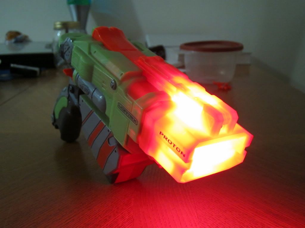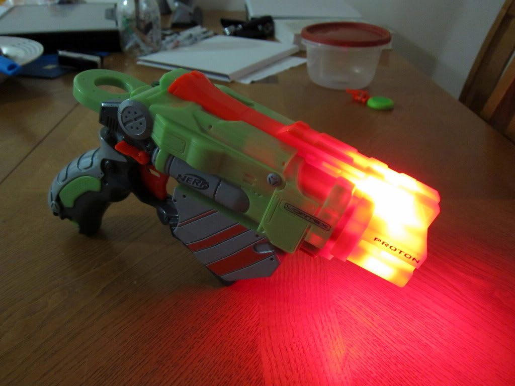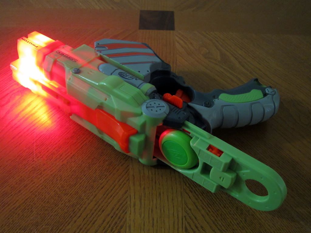
My camera is over-exaggerating the lighting effect; it's about 25% less bright than it seems.

The Proton pistol is styled as an energy weapon; the lighting effect emphasizes this.

The lighting effect is also visible from the rear breech. This adds a nice touch.

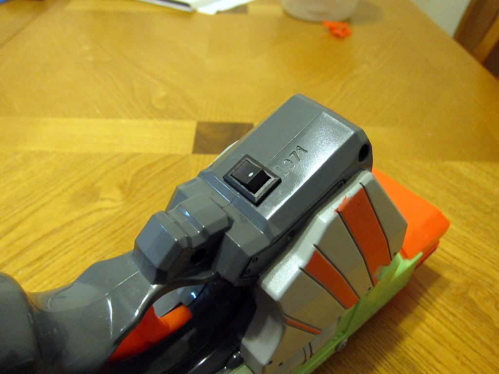
The lighting effect is turned on and off with a small rocker switch in front of the trigger.
DISASSEMBLY
Pistol Frame
Front Cowling
The frame of the Proton pistol is held together with twelve screws. Ten screws are located on the side of the pistol while the other two are on the front of the pistol. Remove these screws with a size 0 Philips head screwdriver to avoid stripping the screws.
Opened Frame
Remove the front cowling of the pistol and carefully pry the frame apart. You don't have to worry about any secret pegs, springs, or glued joints; the frame should easily separate with a bit of patience.
Spring Module
Remove the spring module. It is attached to the frame with two screws. Fortunately, the Proton pistol seems like it was designed with modification in mind.
SAFETY REMOVAL
Fire Control 1
Fire Control 2
Carefully remove the covering of the fire control module. Some spring might pop out of the module if you aren't careful. It is held together by six screws; two of which are not black. In the picture, the trigger and one of the safeties is removed. Notice how sturdy the mechanism is; the Proton pistol doesn't rely on tiny pathetic nubs of plastic to retain the spring. It's likely much more resistant to wearing than most N-Strike blasters.
Fire Control Safeties
Along the top of this picture you will see three components. The leftmost T-shaped component is responsible for the slick reloading action of the Proton pistol. Keep this component. The middle component prevents the weapon from firing at certain points of the reloading process. Although it is not necessary, I prefer to keep this component. The rightmost component prevents the weapon from firing if there is no disk loaded into the pistol. This component is unnecessary; removing it will allow you to fire non-standard ammunition.
Upper Rail Safeties
In this picture you can see two components removed from the frame and upper rail. These components prevent the weapon from firing if there is no disk loaded into the pistol. Remove these components to provide room for the internal LED wiring.
INTERNAL LED WIRING
You will need two 5mm ultra-bright LEDs (~3V, ~20mA), a ~10 Ohm resistor (brown-black-black-gold), two AAA batteries, a small toggling switch, a battery case, wire, and solder. The battery case shown was scavenged from the "Red-Dot Sight" module of the Nerf N-Strike Recon. Use fine grade sandpaper to sand the LEDs; the LEDs will provide a diffuse light that allow it to blend very well with the orange plastic. Use a soldering iron to build the circuit and use a glue gun to glue the wiring into place. If you cannot find a battery case you can try soldering the wires directly to the batteries, wrapping them in foam, and stuffing them into the pistol grip.

Wiring 1
Wiring 2
Wiring 3
Wiring 4
Wiring 5
Shaved Peg
You need to remove a small portion of this peg to give the wires enough room to squeeze through the upper rail.
Lower LED
Be very careful with the LED mounted under the front cowling. The slide will interfere with the LED if it is not mounted forward enough.
RANGE
~60 feet. Theoretically better with safety removal, but probably unnoticeable.
~2 ricochets in a 3 feet wide hallway.


 Find content


