Jump to content


Photo

Too Much Friction

Discussion coninued in "semi auto firefly valve"

37 replies to this topic

#1 Dyxlesic

Dyxlesic

    Member

  • Members
  • 100 posts

Posted 11 February 2011 - 06:19 PM

Im working on something pretty big, and i dont want to give away too many spoilers or hints.

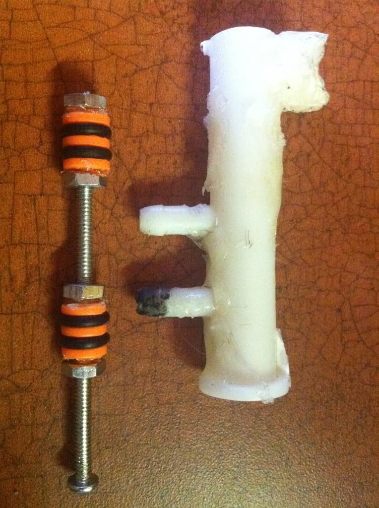
Here is the current setup of one of the parts.
Posted Image
The valve is similar to Cheesy's, using hornet parts. The bolt with the orange O rings slides inside the white piece. It moves back and forth inside of it pulled by a trigger. However, there is way too much friction inside than i would like. What can i do to reduce friction/lubricate it. What type of lube will reduce friction, not melt the plastic or Orings, and not clog the 2 nipples?

all help is greatly appreciated :)

Edited by Dyxlesic, 16 February 2011 - 12:38 AM.

  • 0
Anything you can do I can do backwards

#2 RedShot

RedShot

    Member

  • Members
  • 455 posts

Posted 11 February 2011 - 06:29 PM

I would think that silicon grease would work.
  • 0
Duct tape is like the force. It has a light side and a dark side, and it holds the universe together!
[RedShot]

#3 Inferno Falcon

Inferno Falcon

    Member

  • Members
  • 196 posts

Posted 11 February 2011 - 06:29 PM

http://nerfhaven.com...showtopic=16267
  • 0

#4 Dyxlesic

Dyxlesic

    Member

  • Members
  • 100 posts

Posted 11 February 2011 - 06:38 PM

http://nerfhaven.com...showtopic=16267

thanks for the help. I searched for a post like that and couldent find it. Must've overlooked it or something. will a lubricant clog the holes for the nipples?

Edited by Dyxlesic, 11 February 2011 - 06:41 PM.

  • 0
Anything you can do I can do backwards

#5 utahnerf

utahnerf

    Member

  • Members
  • 339 posts

Posted 11 February 2011 - 06:53 PM

You only need to lightly lubricate the o-rings, so no, it will not clog the nipples. Also, the pressure would most likely push the lubricant out of the way of the nipples.

Edited by utahnerf, 11 February 2011 - 07:26 PM.

  • 0

#6 Daniel Beaver

Daniel Beaver

    HQRSE CQCK

  • Moderators
  • 2,099 posts

Posted 11 February 2011 - 07:24 PM

There's a dirty joke in here somewhere, I know it.
  • 0

#7 Dyxlesic

Dyxlesic

    Member

  • Members
  • 100 posts

Posted 11 February 2011 - 08:26 PM

There's a dirty joke in here somewhere, I know it.

I know. I was gonna say no dirty jokes, but I thought people would just overlook it
  • 0
Anything you can do I can do backwards

#8 Possemhunter

Possemhunter

    Member

  • Members
  • 138 posts

Posted 11 February 2011 - 09:11 PM

If there's that much friction, have you considered smaller o rings?
  • 0

#9 utahnerf

utahnerf

    Member

  • Members
  • 339 posts

Posted 11 February 2011 - 09:28 PM

If he can insert the rod, he probably doesn't need to size down. Only go smaller if you have to force it into the tube, with like.... force.

Edited by utahnerf, 11 February 2011 - 09:29 PM.

  • 0

#10 ricochet

ricochet

    Member

  • Members
  • 108 posts

Posted 11 February 2011 - 09:43 PM

From personal experience I have 3 suggestions.

1. Lubricant always helps, I use barium based lubricant from mcmaster.

2. Scale down from 2 o-rings to 1 o-ring on each orange piece, unless of course, your design can't sacrifice them. Less o-ring contact = less surface area to apply friction inside the cylinder.

3. Using thinner wall thickness o-rings will reduce surface area, once again, reducing o-ring contact, thus reducing friction. For example, switch from a 1/8" wall thickness to 1/16".
  • 0

#11 VelveetaAvenger

VelveetaAvenger

    Member

  • Members
  • 630 posts

Posted 12 February 2011 - 03:48 AM

There's a dirty joke in here somewhere, I know it.

I know. I was gonna say no dirty jokes, but I thought people would just overlook it


Nerds never overlook a dirty joke. Never!
  • 0
"I never saw Beastmaster, I just wanted to be cool..."

#12 Split

Split

    Member

  • Members
  • 1,771 posts

Posted 12 February 2011 - 09:58 AM

3. Using thinner wall thickness o-rings will reduce surface area, once again, reducing o-ring contact, thus reducing friction. For example, switch from a 1/8" wall thickness to 1/16".

Close, but not quite right. For the sake of having the correct information, reducing the outer diameter (OD) of the oring actually reduces the normal force between the oring and the surface, thus reducing friction. Same effect, different reason.

If that doesn't make immediate sense to you, imagine the thickness of the o-ring as a spring. If the OD is 5/16", but the hole it has to fit into is only 1/4", the OD will have to reduce by 1/16" - it'll have to compress. Because it's acting like a spring, the force it's pushing back with as it's being compressed increases with the compression distance. So if the o-ring is only 9/32" (in between 5/16 and 1/4) it'll have to compress less and will exert less force on the surface that's compressing it.


As for this particular issue, those look like stock parts to me, so they probably fit fine and just need some lube. See Captain Slug's thread about lube, already linked in here.

Edited by Split, 12 February 2011 - 09:59 AM.

  • 0
Teehee.

#13 ricochet

ricochet

    Member

  • Members
  • 108 posts

Posted 12 February 2011 - 11:43 AM

3. Using thinner wall thickness o-rings will reduce surface area, once again, reducing o-ring contact, thus reducing friction. For example, switch from a 1/8" wall thickness to 1/16".

Close, but not quite right. For the sake of having the correct information, reducing the outer diameter (OD) of the oring actually reduces the normal force between the oring and the surface, thus reducing friction. Same effect, different reason.

If that doesn't make immediate sense to you, imagine the thickness of the o-ring as a spring. If the OD is 5/16", but the hole it has to fit into is only 1/4", the OD will have to reduce by 1/16" - it'll have to compress. Because it's acting like a spring, the force it's pushing back with as it's being compressed increases with the compression distance. So if the o-ring is only 9/32" (in between 5/16 and 1/4) it'll have to compress less and will exert less force on the surface that's compressing it.


As for this particular issue, those look like stock parts to me, so they probably fit fine and just need some lube. See Captain Slug's thread about lube, already linked in here.


Makes sense, my suggestion was just based off my personal experience and experimentation with o-rings and valves. Good little tidbit of info to know. Props.

Edit: Would this still be the cause of extra friction if the OD of the o-ring wasn't compromised? For example, using a 1/8"x1/4"x1/2" and a 1/16"x3/8"x1/2" (notice only the OD stays the same with a wall thickness change). I assumed it was a surface area change, rather than a o-ring deformation/compression change, because in theory they should be compressing the same. That thought assumes you match the correct OD rod to the same ID o-ring.

Edited by ricochet, 12 February 2011 - 11:56 AM.

  • 0

#14 Split

Split

    Member

  • Members
  • 1,771 posts

Posted 12 February 2011 - 12:30 PM

Would this still be the cause of extra friction if the OD of the o-ring wasn't compromised? For example, using a 1/8"x1/4"x1/2" and a 1/16"x3/8"x1/2" (notice only the OD stays the same with a wall thickness change). I assumed it was a surface area change, rather than a o-ring deformation/compression change, because in theory they should be compressing the same. That thought assumes you match the correct OD rod to the same ID o-ring.

It gets a bit more complicated here. If you have both of those o-rings on the same shaft ("rod OD" doesn't change), the o-ring with the larger ID has more room to move around, so the rubber material doesn't need to compress as much (it'll just move into the empty space). In this scenario, bigger ID is better (might be difficult to keep a good seal though).
If you have each o-ring on a shaft whose OD matches the o-ring's ID, the o-rings have to compress the same distance. It's easier to compress a big object by 1/2" than a small object by .5", which is probably obvious, but comes back to materials science. Since the thicker o-ring has more material, and they both have to compress the same distance, it'll be easier to compress. In this scenario, the thicker o-ring is better.
  • 0
Teehee.

#15 Dyxlesic

Dyxlesic

    Member

  • Members
  • 100 posts

Posted 12 February 2011 - 04:46 PM

Would this still be the cause of extra friction if the OD of the o-ring wasn't compromised? For example, using a 1/8"x1/4"x1/2" and a 1/16"x3/8"x1/2" (notice only the OD stays the same with a wall thickness change). I assumed it was a surface area change, rather than a o-ring deformation/compression change, because in theory they should be compressing the same. That thought assumes you match the correct OD rod to the same ID o-ring.

It gets a bit more complicated here. If you have both of those o-rings on the same shaft ("rod OD" doesn't change), the o-ring with the larger ID has more room to move around, so the rubber material doesn't need to compress as much (it'll just move into the empty space). In this scenario, bigger ID is better (might be difficult to keep a good seal though).
If you have each o-ring on a shaft whose OD matches the o-ring's ID, the o-rings have to compress the same distance. It's easier to compress a big object by 1/2" than a small object by .5", which is probably obvious, but comes back to materials science. Since the thicker o-ring has more material, and they both have to compress the same distance, it'll be easier to compress. In this scenario, the thicker o-ring is better.

I think my head just exploded
  • 0
Anything you can do I can do backwards

#16 Jewstein

Jewstein

    Member

  • Members
  • 81 posts

Posted 12 February 2011 - 04:50 PM

There's a dirty joke in here somewhere, I know it.

I know. I was gonna say no dirty jokes, but I thought people would just overlook it

Nerds never overlook a dirty joke. Never!

If he can insert the rod, he probably doesn't need to size down. Only go smaller if you have to force it into the tube, with like.... force.

Yeah, we really don't overlook dirty jokes. We can also find the humor in little things.

Back on topic, silicon lubricant or Jig-A-Loo should work,

Jig-A-Loo is an invisible, water resistant lube used in speedcubes in the Rubik's Cubing world as it does no melt the plastic inside the cube, so it should work for what you are doing, and it does not goop up.
  • 0
QUOTE

Most people don't use anything near that thick, so I am curious as to what you are up to? I'd offer to sell you some, but alas... I used all that I had when I upgraded the bullet proof glass on my pope-mobile.

#17 utahnerf

utahnerf

    Member

  • Members
  • 339 posts

Posted 12 February 2011 - 10:29 PM

Yeah, and Ice uses it.
  • 0

#18 Dyxlesic

Dyxlesic

    Member

  • Members
  • 100 posts

Posted 12 February 2011 - 10:35 PM

So i found out the problem: the holes in the orange pieces are slightly crooked. how should i straighten them?
  • 0
Anything you can do I can do backwards

#19 shmmee

shmmee

    Member

  • Members
  • 467 posts

Posted 13 February 2011 - 01:04 AM

So i found out the problem: the holes in the orange pieces are slightly crooked. how should i straighten them?


I'd suggest expanding the holes slightly more than the rod so they have a little bit of wiggle. From there remove the o-rings, and get a brass tube that matches the diameter of the orange plastic parts. Chop off a piece of tube, and split it length wise into two halves. De-burr, goop or epoxy putty the orange pieces onto the rod, then splint them with the brass tube halves to make sure they cure straight. Just don't glue the brass tube to the orange piece.

I have a talent for over complicating things. That may be more work than is needed, guess that would be the OCD way of making sure they are straight.

For lube, i like the grease sold in the little canisters (about as big as a 50 cent piece, and about 1/2" high) in the faucet guts section of the hardware store, It's thick, and makes a more forgiving seal where thinner lubricants wouldn't. It's also marked non toxic, and safe for all o-rings. Though I haven't done any long term testing with it, so i don't know if it gums up after a year or two. That's about my only concern with it so far.
  • 0
"and we should respect the people who make our blasters. Even if we do molest the hell out of them..."
~BritNerfMogul


#20 Doom

Doom

    NH's Official In-House Physicist

  • Administrators
  • 559 posts

Posted 13 February 2011 - 11:20 AM

Like in many past threads, I'll suggest off-the-shelf valves to avoid these problems. Making valves is difficult, as is adapting existing valves to do what you want.

Look at 3-way valves like 6464K11 from McMaster-Carr and MJVO-3 or MAVO-3P from Clippard. These valves do what you want (or at least what I think you want given the layout of the valve you have) for relatively cheap.

Edited by Doom, 13 February 2011 - 04:47 PM.

  • 0

#21 Dyxlesic

Dyxlesic

    Member

  • Members
  • 100 posts

Posted 13 February 2011 - 12:17 PM

So i found out the problem: the holes in the orange pieces are slightly crooked. how should i straighten them?


I'd suggest expanding the holes slightly more than the rod so they have a little bit of wiggle. From there remove the o-rings, and get a brass tube that matches the diameter of the orange plastic parts. Chop off a piece of tube, and split it length wise into two halves. De-burr, goop or epoxy putty the orange pieces onto the rod, then splint them with the brass tube halves to make sure they cure straight. Just don't glue the brass tube to the orange piece.

I have a talent for over complicating things. That may be more work than is needed, guess that would be the OCD way of making sure they are straight.

For lube, i like the grease sold in the little canisters (about as big as a 50 cent piece, and about 1/2" high) in the faucet guts section of the hardware store, It's thick, and makes a more forgiving seal where thinner lubricants wouldn't. It's also marked non toxic, and safe for all o-rings. Though I haven't done any long term testing with it, so i don't know if it gums up after a year or two. That's about my only concern with it so far.

Thanks, ill give that a try. would it retain the seal if i only used one O-ring one each end instead of 2?

Like in many past threads, I'll suggest off-the-shelf valves to avoid these problems. Making valves difficult, as is adapting existing valves to do what you want.

Look at 3-way valves like 6464K11 from McMaster-Carr and MJVO-3 or MAVO-3P from Clippard. These valves do what you want (or at least what I think you want given the layout of the valve you have) for relatively cheap.

I looked at the valve, and i dont really understand how it works, or how i could manipulate it to be used in this situation. it looks similar to the piece im using, yet completely different. could you explain what its used for/how it works and how i could use it? the valve i made is sort of a hybrid between atomatrons and cheesys.
  • 0
Anything you can do I can do backwards

#22 Doom

Doom

    NH's Official In-House Physicist

  • Administrators
  • 559 posts

Posted 13 February 2011 - 12:47 PM

I looked at the valve, and i dont really understand how it works, or how i could manipulate it to be used in this situation. it looks similar to the piece im using, yet completely different. could you explain what its used for/how it works and how i could use it? the valve i made is sort of a hybrid between atomatrons and cheesys.


Which valve did you look up?

The basics of these valves have been well understood by spudgunners for many years (with sleeve valves, at least), and they're not new to Nerf either. CaptainSlug recognized their ability to pilot "backpressure tanks" back in 2007, though perhaps not fully as he did not apply them in combination with the right valve to ABP5K. I applied the same basic logic to pilot QEVs (i.e. manufactured "backpressure valves") in 2008. You might also be interested in TantumBull's work with one of these valves.

The links above should be very helpful for you.

I am not very familiar with atomatron's or cheesypiza001's work, but what they've made seems to be approximately what I have been doing since 2008.

Edited by Doom, 13 February 2011 - 01:01 PM.

  • 0

#23 Dyxlesic

Dyxlesic

    Member

  • Members
  • 100 posts

Posted 13 February 2011 - 04:00 PM

I looked at the valve, and i dont really understand how it works, or how i could manipulate it to be used in this situation. it looks similar to the piece im using, yet completely different. could you explain what its used for/how it works and how i could use it? the valve i made is sort of a hybrid between atomatrons and cheesys.


Which valve did you look up?

The basics of these valves have been well understood by spudgunners for many years (with sleeve valves, at least), and they're not new to Nerf either. CaptainSlug recognized their ability to pilot "backpressure tanks" back in 2007, though perhaps not fully as he did not apply them in combination with the right valve to ABP5K. I applied the same basic logic to pilot QEVs (i.e. manufactured "backpressure valves") in 2008. You might also be interested in TantumBull's work with one of these valves.

The links above should be very helpful for you.

I am not very familiar with atomatron's or cheesypiza001's work, but what they've made seems to be approximately what I have been doing since 2008.

extremely impressive list. Im just new to working with external hardware and parts such as those you listed, and am relatively new to the haven. Your and slugs work is extremely impressive, but its not exactly what i was going for. Im looking for a piston like motion similar to the last 2 links you sent. My current valve stroke and trigger stroke matches up exactly with the full piston stroke of my valve i have made, and it is compact enough to fit where i need it. it seals perfectly, fits, and works. the only problem is its crooked and there is too much friction.
Again, i cant emphasize how amazing the work you guys have done is, its just not exactly what i need for this specific project.
*spoilers*
When i said hybriding the 2 valves together, it is litterly what i am doing. It is like cheesys, using hornet parts and a firefly shell and turret for a semi automatic valve, but it has been re-worked in order to work with a backpressure tank/QEV like atomatrons as apposed to a at2k tank like in cheesys. this way, it is simplified, there is no need for a 3rd seal, and no need for another mechanism to pull the pin on the tank. I hope that makes sense
  • 0
Anything you can do I can do backwards

#24 shmmee

shmmee

    Member

  • Members
  • 467 posts

Posted 13 February 2011 - 04:40 PM

*spoilers*
When i said hybriding the 2 valves together, it is litterly what i am doing. It is like cheesys, using hornet parts and a firefly shell and turret for a semi automatic valve, but it has been re-worked in order to work with a backpressure tank/QEV like atomatrons as apposed to a at2k tank like in cheesys. this way, it is simplified, there is no need for a 3rd seal, and no need for another mechanism to pull the pin on the tank. I hope that makes sense


I've been working on the exact same thing with a DTG. Only I've been having sealing issues with the stock hornet trigger tube, so I'm going back to my homemade brass tube trigger valve which seals perfectly without doubbleing up on the o-rings and reducing friction. Or at leas i thought I was untill Nerkum posted a youtube link of the clipard valve integrated into a magstrike operating a big salvo tank. nerkums cliffard valve He presented it on page 2 of Buffdaddys semi-auto salvo thread page 2 of Buffdaddys Semiauto Salvo. Now i'm just annoyed my nerfing budget is spent. This may be a good time for both of us to listen to Doom.
  • 0
"and we should respect the people who make our blasters. Even if we do molest the hell out of them..."
~BritNerfMogul


#25 Doom

Doom

    NH's Official In-House Physicist

  • Administrators
  • 559 posts

Posted 13 February 2011 - 05:12 PM

extremely impressive list. Im just new to working with external hardware and parts such as those you listed, and am relatively new to the haven. Your and slugs work is extremely impressive, but its not exactly what i was going for.


Based on what you wrote, it sounds like exactly what you want. You might not understand the system fully yet, but once you do, I bet you'll see the advantages of off-the-shelf valves and change your mind.

Im looking for a piston like motion similar to the last 2 links you sent. My current valve stroke and trigger stroke matches up exactly with the full piston stroke of my valve i have made, and it is compact enough to fit where i need it.


I doubt you couldn't adapt some off-the-shelf valve to work. You can't make the button be pressed at the end of the stroke? A small one like 62475K11 at McMaster-Carr could definitely fit, would seal perfectly, and would be easy to trigger.

Regardless, it's your project, so ultimately the choice is yours. I might get a little carried away with this subject, but I think it's justified as people spend way too much time trying to make valves.

Or at leas i thought I was untill Nerkum posted a youtube link of the clipard valve integrated into a magstrike operating a big salvo tank. nerkums cliffard valve He presented it on page 2 of Buffdaddys semi-auto salvo thread page 2 of Buffdaddys Semiauto Salvo. Now i'm just annoyed my nerfing budget is spent. This may be a good time for both of us to listen to Doom.


nerkum's video is a good example of what these valves can do.

If you're on a budget, I'd suggest trying eBay to find valves. You'll have to wait to find specific types of valves, but it's worthwhile. If you want Clippard valves, finding a local Clippard distributor (see Clippard's website) is the best way to get those valves for cheap, however. The distributors seem to get a significant discount.
  • 0


2 user(s) are reading this topic

0 members, 2 guests, 0 anonymous users