The Fallopian 2 is an internal pump action platform. It was derived from looking at a PAS and the FAL-1 and trying to relocate where the floating tubes occur.
Advantages:
1. Easy to construct
2. Designed to seal better (with only 1 locking seal compared to 2 in the FAL-2)
Disadvantages:
1. Longer blaster (slightly longer without barrel, much longer with barrel)
2. Draw ratio limitations*
There will be a lot of similarity with the Rainfire, although this wasn't inspired or based upon it. There is just so much you can do with tubes inside tubes. A pretty crucial difference is that the catch does not move.
There is also high similarity with Beaver's plunger-prime system. The FAL-2 is also plunger-prime. However, the plunger tube is "free floating" as opposed to anchored around another pipe.
Demo blaster: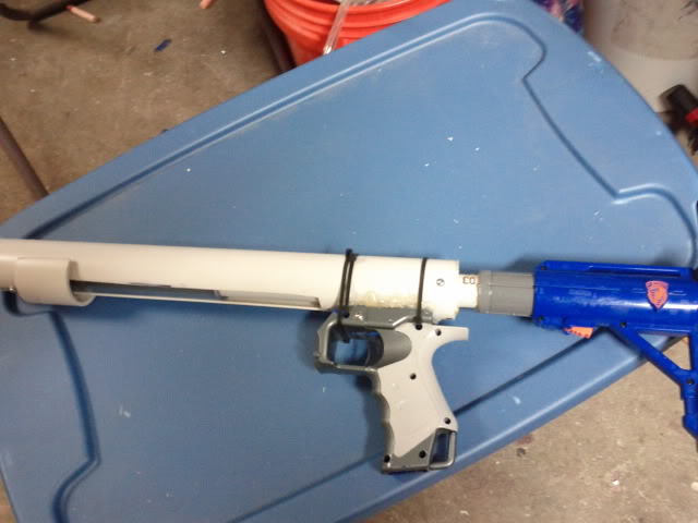
This blaster is 16" long without stock or barrel. It features a full-length plunger rod as opposed to a demi-rod, thus adding around 4" of length (with stock) that could've been removed by moving the stock and handle forward relative to the catch.
It has 10" of spring and 5.25" of draw. Obtaining 6.5" of draw would require 2.5" of compression (nb: not necessarily precompression) spacer to be added behind the spring and an elongation of the blaster by slightly over 2.5".
Plunger Rod and *draw considerations
Due to how the lip of the plunger tube must stop before hitting the catch spring, and then must also extend forward to no more than past the lip of the plunger rod seal, we have this essential equality:
[Draw] <= .5 * [Distance from back of plunger head to spring rest]
In the blaster mentioned, there is .5" of space from the seal to where the spring starts, the spring is 10", and the spring rest is precisely the front catch plate. Thus I am able to obtain 5.25" of draw, and also why moving that up to 6.5" requires the given spacer.
Once this little bit is understood, the rest of the blaster is extremely simple. Here is my plunger rod: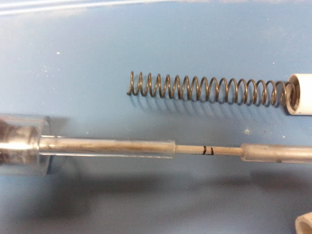
Notice that bit of tube between the rod and the back of the skirt seal. The rod itself is a unidirectional design consisting of 3/8" ID 1/2" OD tube over 3/8" OD aluminum rod. Since the catch surface is semicircular, the 1/8" depth catch contributes enough surface area to make the blaster immune to "drop-firing"
The markings on the rod are to help me measure where the plunger tube will end (it is the one on the left) and where the inner tube support will end (the one on the right). Notice the bit of overlap between the two: this allows the plunger tube to remain support at all times.
Finally, the length of your plunger rod should be enough to just barely pass the end of the catch. The simplest construct method is to over-estimate by a few inches and trim the excess later.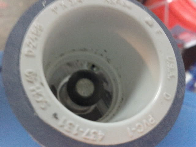
Floating the plunger tube
The best thing ever: 1" PVC nests nicely inside 1.25" PVC which nests nicely inside 1.5" thinwall PVC. The middle pipe will be our plunger tube, and the other two the inner and outer float supports.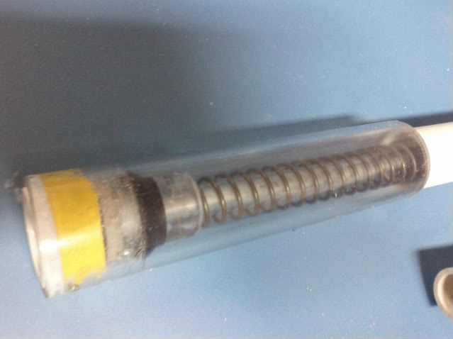
The plunger tube is of length
[Length PT] = [Length space before sealing point] + [Buffer space (~1/8")] + [Draw]
"Space before sealing point" in the front consists of the bushing and the space in front of the plunger head (I have a neoprene square cross-sectional o-ring to act as impact dampening). The buffer space is the gap you want to leave between the actual point of seal and where you want the plunger tube to stop moving. If this is 0, there is a chance of your seal just falling out of the plunger tube.
A large portion of "space before sealing point" is a 1"->1/2" bushing which forms the female receiver of the locking seal. It will make more sense later.
I realized there was some confusion here so this is a diagram of what I meant:
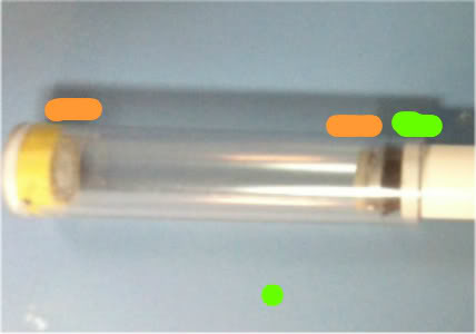
The orange parts are what I consider "space before sealing point" and the neon green is "buffer space" The orange space has no multiplicative length effects (i.e. adding 1" there will just be a flat 1" length addition to your blaster) and does not affect draw. The green space will affect draw and thus is under a 2x multiplier.
...
Here is the full internal mechanism:
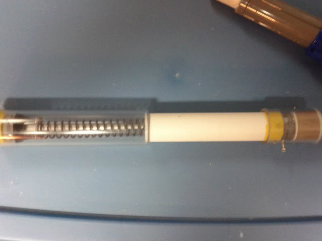
The clear pipe is 1-1/4" PVC. The white pipe is 1" PVC, with a lip beveled to fit around the plunger head seal. The yellow section is electrical tape binding a 1/2" delrin spring rest to the 1" pvc (there is also super glue). As the is no real stress on these parts a high strength bond is not critical. The grey sections are 1/4" polycarbonate pieces finishing up the rainbow catch. The bit of brown at the back is teflon tape around a 1"->3/4" bushing.
Here is the system priming:
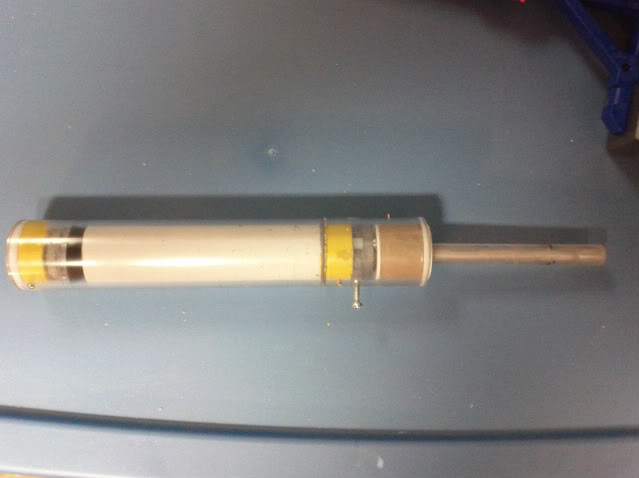
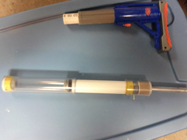
And primed:
Outer shell
The outer float support is the outer shell. I used a piece of leftover rainbowpump priming shroud and just reappropriated it. The cuts should be pretty obvious. The only thing left is a barrel adapter. I took two 1-1/4"->1/2" bushings and cut them down to make 1 super long bushing and then ran some 1/2" PVC halfway through. This PVC stub is the male counterpart to the female receiver on the plunger tube.
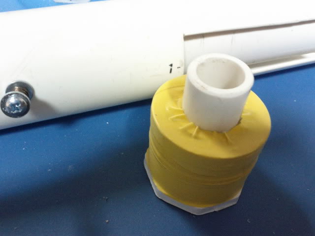
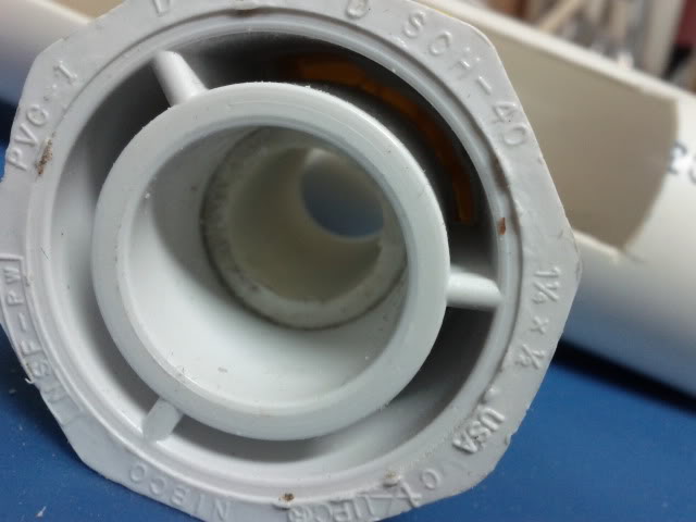
Finally, you will want to drill a hole for the rainbow catch, mount the male barrel receiver to the outer shell with adhesives or fasteners and mount the catch/spring rest/stock section of the internal mechanism.
You will also need to mount a handle and create a trigger.
The priming handle is 2" PVC attached to a section of 1.5" PVC coupler attached to 1.5" thinwall PVC attached to the female barrel receiver on the plunger tube. You may discover superior methods.
Miscellaneous
Completed blaster, priming

Completed blaster, primed
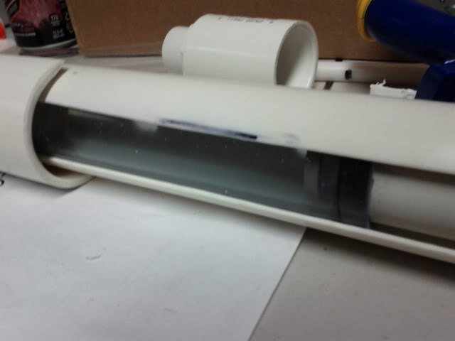
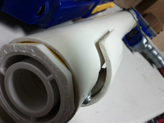
Porn shot:
Edited by CaptainSlug, 01 November 2017 - 07:41 AM.


