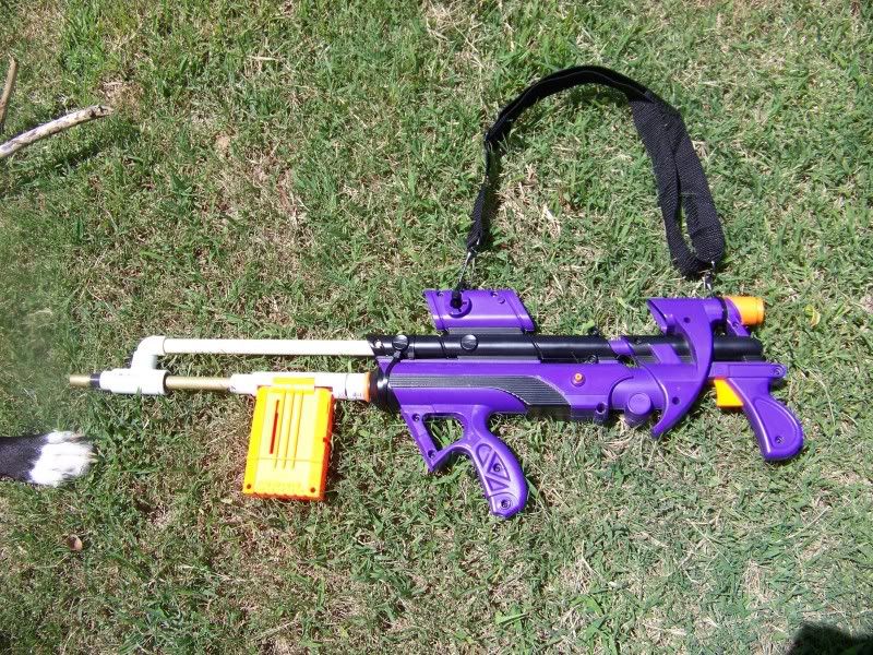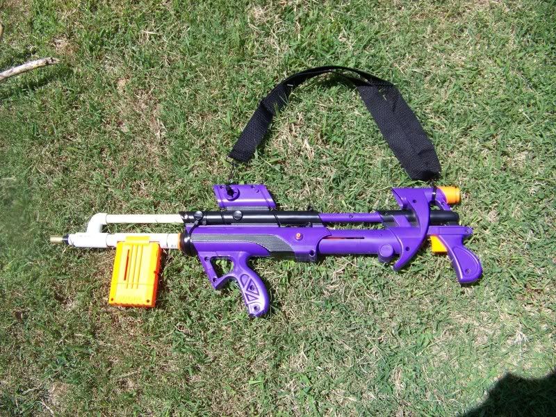
Goals of this mod:
- Coupler system to accept CPVC and PVC/PVC + nested barrel setups
- Attachment point for a removable linked breech
- More reliable plunger head
- Increased draw
- Reinforcements to handle 38+ lbs of draw force
- Air gun integration
I'm not going to bother with the introductory stuff like disassembling the gun and taking out ARs. There's plenty of BBB writeups you can follow. Furthermore, I've done this project over 2 BBBs, so the shell color you see will change.
-------------------------------
Reinforcements
--------------------------------
Let's start with the catch. Add epoxy putty to the catch plate and also the plunger rod:

You want the catch nub on the catch plate to be enlarged enough such that the plunger rod has no horizontal "wriggle room"
I also found that my catch plate was loose in the catch well itself, so I added some epoxy putty to the guide ridges on the catch plate:

I only had to add the epoxy putty to the ridge that went into the side of the shell that contains the internals (right side, if the front of the gun is pointed away from you). To ensure the catch plate would still fit, I pressed the catch back into the well while the putty was still soft and used a knife to cut away the excess.
In the picture, you can also see how the addition to the catch nub is rounded on one side and more perpendicular on the other. The rounded side faces the front and allows for the plunger rod to still slide back under the catch.
Next, buff up on springs:

I use McMaster part 96565K36 for all my catch replacement springs. I also had to buff up the trigger spring because I did a crap job cleaning putty off of the catch well so the catch was a bit sticky.
Finally, add a washer to the back of your plunger tube:

I pushed the washer most of the way down, threw some goop on it, and pushed it the rest of the way in. The washer in question is a 9/16 SAE washer. Actual dimensions are 1-3/16" OD x 19/32" ID. This step serves two purposes. It creates a better force distribution on the back of the plunger tube because the steel won't deform as much as the bare plastic, and it also decreases the ID, allowing use of springs with smaller ID (like the +bow spring) without the spring twisting out of the plunger tube. Blacksunshine solved it by flaring his springs. This is my method.
Because of the smaller ID however, you will also have to shave down the corners of your plunger rod:

Ignore the cut of peg for now.
-------------------------------
Improved plunger head
--------------------------------
Bend the "cup" shape of the plunger head backwards, wrap wire (or some other flexible round material) around the base of the plunger head, and add hot glue:

This expands the gasket which helps ensure a solid seal.
You should also cut off the top of the plunger head:

Also, reinforce the plunger head by adding washers to the orange disc that compresses the springs. This has been done before, so consult b00m13 or Blacksunshine's writeups if you need help.
Method 2: Replacing the plunger head
Materials:
1.5" long 8-32x machine screw
1" long 8-32x 1/4" OD round aluminum standoff (threaded spacer)
Preparing the plunger rod
Start by cutting off the nub that holds the orange disc and plunger head and sanding the tip flat:

Drill a 1/4" hole 1" deep for you standoff

Take your 18-32x 1/4" OD aluminum standoff and epoxy that sucker in. Then add epoxy putty around it for extra support.

The standoff is threaded for a 8-32 screw to screw on the plunger head.
Building the plunger head
Be sure to check out this post too, as it is both lighter and better sealing.
This step is an adaptation of the Longshot plunger head replacement. You want to sandwich a neoprene washer in between metal washers. Here are ideal dimensions:
- 1x 1-1/4" OD x 1/8" ID Neoprene washer
- 1x 1-1/16" OD x 1/8" ID Steel washer (back)
- 1x 1" OD x 1/8" ID Steel washer (front)
Here's what I ended up using, due a lack of materials at ACE:
- 1x 1-1/4" OD x 3/16" ID Neoprene washer
- 1x 1/2" SAE washer (1-1/16 OD x 17/32 ID)
- 1x #10 SAE washer (1/2 OD x 7/32 ID)
- 2x 3/4 OD x 5/32 ID steel washer
- 1x 1" OD x 7/16 ID fiber washer
- 1x 7/16 OD x 7/32 OD fiber washer
The first 3 steel washers create the "back" and the next three create the "front". I nest the washers by putting the smaller one in the larger one, and then glue both of them to the third for support and cohesion. The following two pictures should help enough:


In the first, you can kind of see the third supporting washer hidden behind the front two through the hole.
-------------------------------
Expanding plunger tube/increasing plunger draw
--------------------------------
If you followed method 1 for the plunger head, you're going to want the white AR piece. Dremel it out fully, and bevel the inner lip a bit:

Slap it over your plunger head:

Bam! About .5" of increased volume.
If you followed method 2 for the plunger head you need to do absolutely nothing. The washers will be lying flush against the plunger rod, which gives you the .5".
Notice that method 1 requires expanding the plunger tube out; method 2 reduces the plunger rod in.
To allow for the rear section of shell to move enough for the extra draw, you may also need to dremel down the ridges in the front section of shell that run up along to the front sight. I don't have a picture of this, because you need to dremel down those ridges anyways for a linked breech, so I didn't think it was necessary for the plunger draw expansion. I've been informed it is.
Edited by Zorn's Lemma, 18 September 2009 - 12:32 PM.


