Jump to content


Aeromech's Content

There have been 378 items by Aeromech (Search limited from 27-December 96)


By content type

See this member's


Sort by                Order  

#338767 Handmade Rainbowpump Variant

Posted by Aeromech on 07 May 2014 - 05:57 PM in Homemades

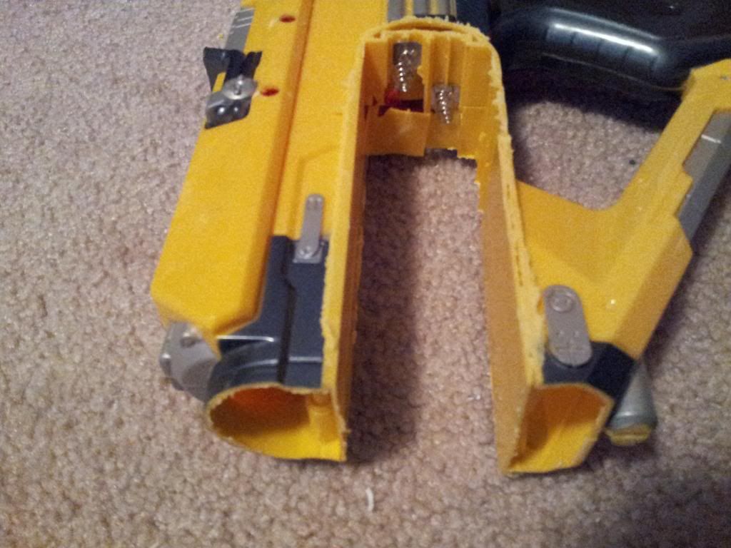
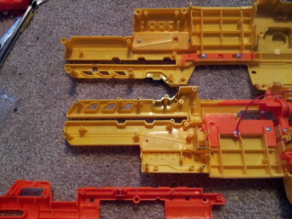
I'm sure there are more exact ways of finding the center of the polycarbonate disk on the plunger head then eyeballing it.

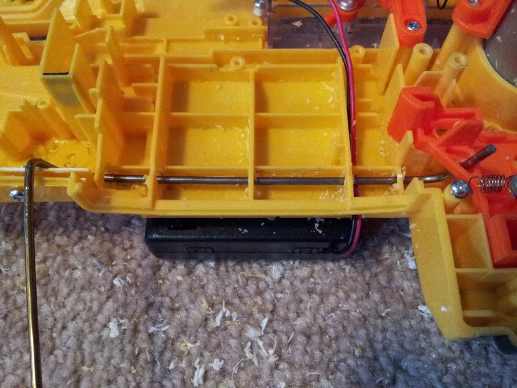
...it seems to me that you are relying solely on the force of the screw from the priming bar to keep the plunger rod in place.


Thanks! Edited the write up to reflect this. And you are correct. If it does loosen up, all it takes to re-tighten it is a screwdriver to the plunger head and rotating it couple of degrees. I would rather not use adhesives and be able to change my design in the future if I see fit than lock the thing down permanently. After all, I'm still learning and I want to try out some ideas in the future.


That must have taken a while with no power tools.


You betcha. Took me three days to complete.


Good work showing what can be done *without* many power tools. One thing though; if you've got a drill, how hard is it to get a couple of hole saws for disc cutting? I think I got my set at sears for like $15, and I'd gladly pay that for not needing to do all the work you do to get discs.


I got the correct diameter hole saw from Ace hardware, and was super excited to use it, knifed through the packaging and discovered my beautiful hole saw shank was too large to fit in my wimpy 3/8" drill chuck. So I adopted this method instead of searching for such a device.


#338761 new style RainbowPump Writeup

Posted by Aeromech on 07 May 2014 - 11:36 AM in Homemades

True statement here. But you do have to slightly lift your face off the gun when priming (obviously). It's not anything to worry about.

Also, a sheath adds considerable weight.


Sheaths do add weight. My rainbowpumps all have sheaths so I can continuously stay "on target." You could drill holes in them if you want to take off maybe 15% of the mass of the tube.

On another note I made sure I did not peek at your rainbowpump design until after I submitted my rainbowpump design to the homemade contest. That being said, sweet writeup.


#338759 NH Homemade Contest Submission Thread

Posted by Aeromech on 07 May 2014 - 11:30 AM in Homemades

http://nerfhaven.com...t=0#entry338754
My Rainbowpump submission. Definitely "plusbow class."

Posted Image


#338754 Handmade Rainbowpump Variant

Posted by Aeromech on 07 May 2014 - 01:00 AM in Homemades

Posted Image
Just like this.

Posted Image
Back out both the top and bottom screws on the lower, and slide the "upper" 1-1/4" PVC tube all the way into the PVC tee. Remove the top screw and drill through this hole through the 1-1/4" PVC lower. Screw the top screw all the way into the tube, securing the upper to the lower. Repeat this process with the bottom screw.


The Barrel Assembly

Posted Image
Take a 2" segment of 1/2" PVC and hammer it into your wye. Drill a 7/32" hole into the rear of the wye, securing the PVC segmentm with one of your 6-32 screws.

Posted Image
This screw prevents darts from being sucked into the plunger tube. When the plunger is pulled back, a vacuum is created, pulling darts into the tube. This screw gets in the way of that, so no darts will be lost in the blaster's insides.

Posted Image
This is a 16" piece of 1/2" CPVC hammered into a 3" segment of 1/2"PVC. This is your actual barrel.

Posted Image
Using a knife, bevel out the inside edge of the PVC-CPVC barrel, allowing darts to more easily be pushed out of the barrel.

Posted Image
Here's the final assembly. Load the darts in through the top ball valve. The "magazine" is just the diagonal 1/2" PVC tube; the darts fit loosely in here. This one is actually a bit longer than I like it; the longer your hopper magazine, the lower your ranges will be. When firing the blaster, air pressure forces a dart forward and out through the barrel.


The Handle

Here is the technique I use to make handles. Everyone's hand is different, but below is the general shape I used, that changed over the course of the trimming. The handle consists of three plates of cutting board, screwed together to increase thickness.

Posted Image
Start by tracing out a basic shape onto your cutting board.

Posted Image
For hard to reach posts, use your drill with a large diameter bit to make sharper corners.

Saw out the general shape, then use your files to trim the part down to your desired shape.

Posted Image
Trace around the completed section twice. The handle will consist of 3 sheets of cutting board screwed together.

Posted Image
Modify your two "outer" plates to include the extensions on the top. These will hold the trigger in place. Roughly cut these shapes out.

Screw together the three pieces with 3/4" long 6-32 screws, your can make a faux-countersink using a 5/16" drill bit and drilling in only 1/8 to 3/16 of an inch. This sinks the screw heads in so it doesn't hit your hand, and this technique save you from buying a whole new set of screws.

Posted Image
File down the edges of the handle to be flat...

Posted Image
Then bevel the corners. From here, blend together the edges to round them out with the course file. The final shape is largely determined by feel.

Posted Image
File out the top plane with the round part of the course file. This creates a plane that is concave-up and will better interface with the body of the "lower;" two round surfaces will connect at opposed to one round and one flat.

Posted Image
Make a mark on the "lower" the location of the trigger screw.

Posted Image
Take a scrap piece of polycarbonate and trace out the shape of the internal section of the trigger, it should be roughly semicircular.

Posted Image
Just like that.

Posted Image
Drill though the rotation point with a 7/32" drill bit.

Posted Image
Insert a small screw into the trigger as shown, then ream out the rotation hole with a 9/64" drill bit. This allows the trigger to rotate freely.

Posted Image
Drill a hole, perhaps 5/16" diameter, into one of the sides of the handle.

Posted Image
This, with the small trigger screw we just inserted, will create a captive trigger; it has a limited degree of rotational motion, and cannot spin all the way around.

Posted Image
Drill all the way through the rotation holes on the assembled handle with a 7/32" drill bit, so a 6-32 screw will fit in there.

Next we need to spring-load the trigger so you can be like all the cool kids.

Posted Image
Drill one of your small screws into the base of the center plate of the handle.

Posted Image
Drill your last small screw into the trigger.

Posted Image
Inserting a small piece of catch spring, held captive by the two small screws, will yield in a spring-loaded, captive trigger.

Posted Image
Drill and tap a hole at the rear end of the trigger, and insert a flat-head 6-32 screw in there.

Posted Image
Mark on the handle the location where the catch screw and the trigger screw will connect. The flat-top screw we previously added to the trigger allows the trigger to hit the catch screw with a little more surface area, and also prevents the metal of the catch screw from wearing down the polymer polycarbonate of the trigger.


Attaching the Handle

Posted Image
Back out the two "lower" screws, and remove the "upper" assembly from the "lower."

Posted Image
Line up these marks on your "upper" and handle.

Posted Image
Mark at least two places on the bottom of the lower assembly where you want to screw in the handle.


Drill only one of the holes into the top of the handle. Make sure you drill deep enough to secure a 1-1/4" 6-32 screw, so use a 7/32" drill bit. Here, I used a tiny piece of blue-tac to hold the screw into place on the head of the screwdriver.

Posted Image
Screw in the screw partway into the handle. To reach the screw, you will have to drill two holes at the top of the upper tube to align with the holes you wish to use to screw in your handle. A 5/16" drill bit should do the job. The location of these holes are not critical, they just need to be over the handle attachment screws and be large enough that the screw head can fit in there.

Posted Image
Screw in the bottom screw just until a mark is formed.

Posted Image
Tough to see here but the screwing action you just did creates a small dent in the soft polymer of the cutting board. This gives you an exact location for your next drilling action. Once this is done, screw the handle completely onto the lower assembly.

Posted Image
Mine's a little crooked but who's counting?

Posted Image
Bam.

Results
->Now you have a cool blaster that can absolutely compete with the big guys.
->The separable upper and lower assemblies allow for a near universal use with every blaster of this type: you can mix and match any upper to any lower so long as the trigger screw and catch screw line up, and the two rear screws are in alignment.
->This plunger yields a perfect air seal. This is the second time I have achieved such results on a blaster.
->No ranges but the thing hits hard. From 20 feet I cracked the clear cover plate of a plastic clock I was aiming at using slugs.

Posted Image
Killin' Time.

Additional Notes
Damn this thing requires some elbow grease. Fabricating Polycarbonate with man-power is absolutely possible, but it is not easy. This method is meant for newer builders or those without machines to get their feet wet in the hobby.

Posted Image
Threw on a sub-optimal paint job. Will definitely be warring with this blaster, I am totally in love with her.

Now go make a gazillion slug darts.

Post away! I look forward to questions, comments, etc.


#338753 Handmade Rainbowpump Variant

Posted by Aeromech on 07 May 2014 - 12:58 AM in Homemades

Posted Image
Ensure that these tape lines extend all the way to the rear of the PVC tube...

Posted Image
And cut out the remaining material with a hacksaw. File smooth the edges of the slot.


Plunger Assembly, Part 2

Posted Image
Cut out about 1/4 inch of the insulation foam.

Posted Image
Use hot glue to unite the seam

Posted Image
This is one more piece that requires the fabrication techniques described in the catch section, however this piece does not require any sort of precision. It simply serves as a guide for the pump (which will be created shortly.)

Posted Image
The only requirements for this piece are that it fit inside the Clear PVC and plunger rod, and that the "wings" that protrude out of the slots fit snuggly inside the PETG that will make up the pump, as shown.

Posted Image
Drill for 7/32", then tap for 6-32 screws at the center of each of the wings.

Posted Image
Focusing on the back of the plunger tube, drill and tap for the remaining 1-1/4" 8-32 screw.

Posted Image
Drill a small through-hole on the side of the plunger rod, about 3 inches from the end. A 3/32 bit will be sufficient. Save this drill bit.

Posted Image
Cut out a polycarbonate rectangle, 1/2" tall and about 2-1/2" wide. This will be the priming rod that the pump will push back.

Posted Image
Drill and tap for the 8-32 1-1/4" screw. Put the #10 washer over the screw before screwing it into place.

Posted Image
Make a plunger-kebob. The order of said kebob is, from the front, [k26] Spring, Rainbow catch, Foam Insulation, Winged Pump Part.

Several things to note: The 3/32 drill bit is holding the [k26] spring forward. The heads of the screws on the catch are facing rearward. If they were facing forward, the screw heads would interfere with the spring.

The foam insulation tube we cut out earlier serves to soften the impact of the pump when the finished blaster is being pumped. The winged pump piece will hit this foam and not more polycarbonate or the screws sticking out of the catch.

Posted Image
Screw on the priming bar, ensuring that the bar is parallel with the floor of the catch notch on the plunger rod. The purpose of this priming bar is not just to prime the blaster, but also to keep the catch notch level with the catch itself. If the plunger rod was not guided by the priming rod, the plunger rod, being cylindrical, would rotate, and fail to engage the catch. The plunger would not lock back.

The plunger internals are now captive.

Posted Image
To add some padding to the plunger head, apply some stick glue to the head face.

Posted Image
Cut out a disk of craft foam and press it against the plunger head. No padding means that two harder materials will slam together every time the blaster is fired. The padding helps preserve the life of the blaster.


Securing the Internals

Posted Image
Remove the drill bit from the plunger rod and slide the plunger-kebob into the PVC tube.

Posted Image
Push the catch forward so the forward catch disk is aligned with the marked circumference. Drill a 7/32" hole through the PVC and into the Polycarbonate disk being careful not to drill into the nylon rod. Temporarily secure the catch with a 6-32 screw. Drill and tap the hole opposite the temporary screw for a 6-32 screw. Repeat for the two remaining marked areas. The screws should form an "X" in the catch disk, that is, the screws should be diagonal not vertical or horizontal.

Posted Image
One at a time, remove one screw from the catch, countersink, and then replace the temporary screw with a flat headed 1/2" 6-32 screw. Repeat for so all four points are secured with flat screws, flush with the PVC tube.

Posted Image
On the bottom of the catch, the hole drilled in the central catch disk should be visible. Drill a 9/64 hole through this region, making sure this new hole in the PVC is in line with the previously drilled hole in the catch. Do not drill into the catch.

Posted Image
Screw a 6-32 screw into this hole with a small piece of catch spring over the screw. The catch spring should rest on the head of the screw and the body of the PVC tube. When screwed into the catch, the spring is constantly pulling down on the catch, so when the notch on the plunger rod interfaces with the catch, it is secured in place by the force of this small spring. When this screw is pressed up, the catch releases the plunger rod and the plunger flies forward.

Posted Image
Trim off the excess material on the priming bar... the bar should fit inside the 2" PVC without any collision. Also note the secured screw and spring at the top of the photo.

Posted Image
Remember that extra taped bushing from earlier? This will be the piece that maintains the shape of the PVC now that the slots have been completely cut through. Secure this part using the same technique as the catch plate: 4 flat headed screws in a diagonal fashion, all countersunk to be flush with the PVC.

Posted Image
The ring of screws securing the catch mechanism is 9-1/4" away from the rear end of the PVC tube. 9-3/8" would also work. This measurement is important only in the final assembly: when the "upper" and "lower" assemblies are connected, this dimension is necessary for the trigger to properly interface with the catch screw. More on that later...

Posted Image
Here, the screws securing the rear bushing are evident. If you trim your PVC tube a bit too short, (as I did in this case,) simply file away at a bit of the PVC tee, as marked on the tee.

Posted Image
When the rear of the tube is eventually secured in the PVC Tee, this bushing will not interfere with the connection, as seen above.

Posted Image
These are "speed holes." Ignore the weird design, basically just drill three holes 3/16-5/16" wide IN FRONT of the catch mechanism, to stop the formation of a vacuum behind the plunger head. Without these holes, a vacuum can form behind the plunger, drastically slowing down the plunger.


The Pump

Posted Image
"Blueprint" four straight lines down the length of the PETG/Polyester tube to mark the quadrants of the pump.

Posted Image
Mark the slot on the bottom rear of the pump tube, IT should be about an inch wide.

Posted Image
Drill holes at the corners of the slot. Round corners distribute stress far better than sharp corners. This drilling ensures that the pump will not fail under stresses at this point.

Posted Image
Cut out the slot with a hacksaw.

Posted Image
Repeat this corner drilling technique for the front of the pump, and hacksaw away the top half of the forward part of the pump.

Posted Image
Here is the pump with the aforementioned cuts, view from the bottom-side.

Posted Image
Drill and 6-32 holes that align with the hole in the pump piece in the plunger assembly. Leave about 1/8" of space between the pump plate in the plunger assembly and the rear face of the pump. We want the pump itself to push back the priming bar, not the pump plate in the plunger assembly. Countersink these holes.

Posted Image
Test fit into place with the flat headed screws.

Posted Image
The winged "pump plate" serves only to guide the pump. The big hole in the center of the pump plate is to allow the plate to glide over the plunger rod without any resistance. Because the wings fit into the slots on the body tube, the pump cannot rotate, being affixed to the winged plate with screws. Additionally, your pump can now only move forwards and backwards the distance that the slots will allow.

Posted Image
Cut out a piece of the skateboard tape to match the front of the pump...

Posted Image
And secure it to the pump. The skateboard tape already has adhesive, so just press it into place. When everything looks good, secure the pump to the pump plate, locking the pump in place with the rest of the "upper."


Constructing the Lower

Posted Image
Secure the 2" PVC over the PVC tee with gorilla tape.

Posted Image
Drill, tap and countersink the top and bottom of the tube-tee assembly. Remove the gorilla tape.

Posted Image
Cut out this small notch on the bottom front of the 2" PVC tube. This is where the spring-screw from the plunger tube will stick out.


#338752 Handmade Rainbowpump Variant

Posted by Aeromech on 07 May 2014 - 12:56 AM in Homemades

Preface
As I have only recently began building homemade Nerf blasters, it is fitting that I share my first-time experiences with those in a similar position that may have less experience or know-how. This write-up marks the culmination of the lessons learned over two blasters before it, and represents an entry level Rainbow-pump blaster with a modified setup.

Additionally, this homemade guide does not necessitate the use of a drill press, hole saw, or mill. This write-up serves to prove that a new homemade builder can create a durable and reliable blaster using only hand tools. That being said, it is not easy, and those new to homemades should still proceed with caution. I have ample experience with crafting and tinkering, and I was able to figure this out pretty easily. Don't jump in headfirst. I try to point out my reasons behind doing things the way I do herein, and I can only recommend proceeding with a firm understanding of the system.

Credits to:
Ryan McNumbers for his Original Rainbowpump writeup

Stark and the Rainbow clan for the brilliant rainbow catch design

Daniel Beaver for hosting the catch templates.


Strap on those safety goggles and let’s begin. All descriptions shall be located BELOW their reference photo for this write-up.

Raw Materials
McMaster-Carr:
49035K86: Schedule 40 Clear PVC Pipe 1.25”
9562K46: Rotary Shaft Ring Seal, 0.95” to 1.07”
8541K18: Black Nylon Rod, 0.5”
9245K51: 2" OD Clear PETG
9637K26: [k26] Compression Spring, 11” Length
8574K28: Polycarbonate Sheet, 12”x12”x0.25”
96565K36: Catch Spring
4880K636: ½” PVC Wye

Ace Hardware:
1 Box Pan Head 6-32 Machine Screw, 3/4” Length
1 Box Flat Phillips 6-32 Machine Screws, ½” Length
1x Pan Head 8-32 Machine Screw, 1-½” Length
1x Pan Head 8-32 Machine Screw, 1-1/4” Length
1x #10 Washer
1 ft of 2” PVC Pipe
1x 1-1/4” PVC Tee Coupler
2 ft of ½” PVC Pipe
1x ½” PVC Ball Valve
2x 1” to ½” Bushing
1-1/2 ft ½” CPVC Pipe
1/2" of 1/2" CPVC foam insulator tubing
1x Tub of Silicone Grease
1x Tube Lithium Grease

Home Depot:
Plumber’s Goop (Couldn’t find it in Ace)

Walmart:
2 Cutting Boards
Packaging Tape
Craft Foam

Zumiez:
Skateboard Tape (optional, but it’s only $5 for a 4 ft sheet)

Tools
Safety Goggles
Safety Gloves; you’re laughing now but they’re damn helpful.
Hacksaw
Course File
Less-Course File
Rat-Tail File
Phillips Head Screwdriver
Tapping Wrench
6-32 Tap
8-32 Tap
Electric Drill
Set of Drill Bits
Countersink
Sandpaper
Gorilla Tape
Sharpie
Printer
Stick glue
Hot glue gun
Tiny bit of blu-tac
Table Vice


The Genesis of the Design

100_0691_zpsd20135ea.jpg
This is my first series of Homemade blasters, as the figure above illustrates. From bottom to top, the first, the second, and the third blaster in the series. This write-up focuses on the third, which takes the lesson learned from the previous two designs.


General Dimensions

100_0695_zpsfdf529f5.jpg

100_0694_zpsd58c2012.jpg

Complex CAD drawings can be intimidating. Here are some simple drawings that outline the lengths of each large piece. Mechanically, I separated the Rainbow Pump into three sections: The “upper,” “lower,” and “pump,” and the plunger rod to reference later in the writeup. This design actually deviates from the original Rainbowpump design, but allows for new plunger tube assemblies, or “uppers” in this case, to be swapped out easily without having to fabricate a new handle.


Adhere the Bushing

100_0497_zps7f6140b2.jpg
Wrap both of the bushings in plumber’s tape until the bushings fit tightly in the 1-1/4” Clear PVC Pipe. Cut off the excess tape from each bushing. Set one aside.

100_0501_zps4d48d698.jpg
Apply Plumber's Goop around the outer diameter of the Bushing and press it in there firmly. Be sure to perform this step outside. There's toluene in that shit.

100_0502_zps8a9902a0.jpg
This is how I allow the Goop to cure. I let it rest vertically for about 12 to 24 hours, to ensure that the goop doesn't drip out of one side. Maybe superstitious, but in any case keep the tube outside until the goop is fully cured.


The Rainbow Catch

Here are the templates for the rainbow catch, hosted by Daniel Beaver. Print out 2 copies. Make sure you click "actual size" and not "fit to page" when you print, otherwise your templates will be too small.

100_0505_zps44018e2b.jpg
Cut out the templates, and a few squares of polycarbonate...

100_0506_zps60178e6a.jpg
and glue them onto each piece using super sticky stick glue.

100_0507_zps2f80a41c.jpg
Stick it in your vice, and use your course file to trim each side right up the the black line of the outer circle on the template, but do not file away any of the black line itself, this actually represents material that is supposed to remain intact.

100_0509_zpsa6ea0502.jpg
Now file down each corner to form an octagon, again trimming right up to the black line.

100_0510_zps2f293ae4.jpg
Use your file to blend together two of the adjacent sides.

100_0511_zps6a1692be.jpg
The knife is pointing to the blended side. Repeat this blending on all corners to create a circular part.

100_0513_zps96550d81.jpg
Repeat this process of filing flats, then blending them together to all rainbow catch parts.

100_0516_zps1aed9ede.jpg
To create the hole in the catch plate, first drill out a 1/2 inch hole in the center of the plate. If the drill torques the part out of the vice, drill the largest diameter you can, and then ream out the hole to 1/2 inch diameter with your rat tail file. The bottom corners should be square. To create this effect, drill a small diameter hole, maybe 1/16 or 3/32 just inside of those corners. Then, use a knife to carve out the flats on the two walls and the floor of the catch plate.

100_0517_zps59162a86.jpg
Now you have the desired shape. Drill out the outer two catch plates, using a 7/32" drill bit for the outer holes. The center hole should also be 1/2 inch in diameter. Drill through and ream out if necessary.

100_0518_zpsa1025b55.jpg
Use a section of 1/2" Nylon rod to keep the outer holes of the outer two catch plates in alignment while drilling.

100_0522_zps0e2682b3.jpg
Drill and tap the bottom of the inner catch plate, first with a 7/32" drill bit, then a 6-32 tap.

TO TAP: Place a bit of lithium grease on the end of the tapping tool. Once the teeth of the tap have gripped the material, screw one turn forward, then one half turn back. One turn forward, half turn back. Repeat until the desired thread depth is achieved. The grease acts as a means of heat dissipation and ensures smooth entry. The backing out after each turn allows the built-up material inside the hole to clear out. I've broken a tap before by not following these rules.

100_0520_zpsf0a6db55.jpg
After drilling both holes, leave the bit in one of the holes, and tap with the entire assembly in a vice. This will ensure the threads line up once the catch assembly is put together post-fabrication. Tap using the 6-32 tapping bit.

100_0523_zpsbcd89f14.jpg
Screw together the two outer catches. Test fit in a piece of 1-1/4" PVC. That's the catch.


Plunger Assembly, Part 1

There are many plunger head designs out there, but I could not find just a "skirt seal" plunger head. Alas, I found it necessary to improvise. This plunger head yields a perfect or damn-near perfect air seal.

100_0524_zps61fa9930.jpg
Take the second Rainbow catch template, and set up the two outer catch plates onto two pieces of polycarbonate. We are only using these templates for the outer circles this time. For the third piece of polycarbonate, trace around the inside of the rubber ring seal with your sharpie.

100_0533_zpse909f0c3.jpg
This time, file slightly inside of the lines, using the same technique as the catch to file flats, then blend. Repeat for the other outer catch template. The smaller traced template should fit snuggly inside the ring seal.

100_0535_zpsdb582820.jpg
Drill and tap using a 1/8" drill bit followed by the 8-32 tapping bit through each polycarbonate disc. Use the template to center the hole on the larger two disks, and eyeball the center of the small one; the best way to do this, I've found, is to center a water bottle cap underneath this piece, and make a center mark based on the central divet of the bottle cap.

100_0536_zps469b452a.jpg
Screw on a large disk then the small disk onto the longer 8-32 screw. This larger diameter screw is used due to higher stresses that the plunger head encounters.

100_0537_zps327188c3.jpg
Slip on the ring seal, and then screw on the final large disk locking everything in place. There should be a firm force pressing the seal together from the outer two disks. The interior disk is used to keep the seal centered.

100_0503_zpsd0b52343.jpg
Cut the Nylon rod down to 11-1/16". File off both ends with the fine file, ensuring a flat surface on each end of the rod.

100_0693_zps4f69d121.jpg
This is the catch notch in the fully assembled blaster. The front is sloped at 45 degrees, and the rear wall is vertical. When the blaster is primed, the spring exerts a force forward on the plunger assembly. the catch is "caught" in that little notch, and basically gets in the way of the plunger rod, stopping it from moving forward. When the trigger is pressed, the catch is pushed upwards and out of the way of the plunger notch, allowing the plunger assembly to slam forward with the force of a thousand laser beams. The notch itself should be about 1/3 of the diameter of the rod.

100_0538_zps10817a29.jpg
Drill one end about 1 inch deep with a 1/8" drill bit, then tap with the 8-32 tap.

100_0540_zps413a1898.jpg
Screw your plunger head onto your plunger rod.


Blueprinting the Body Tube

100_0543_zpscd5f4605.jpg
At this point, your goop is likely dry. Trim off any extra goop that protrudes outside of the diameter of the clear PVC. No need to trim the rest.

100_0547_zps96eddfcb.jpg
Measure out 11-1/2" from the front of the clear PVC and make a mark on the PVC. Using your gorilla tape, wrap around the tube at the mark, and trace around the tape.

100_0548_zps0037de0d.jpg
When the tape is removed, a circumference of distance 11-1/2" from the front of the PVC remains. This allows for clean placement of screws in the blaster.

100_0549_zps2592991a.jpg
Make four marks around the front of the blaster. These marks can be accurately placed using the hexagonal bushing to locate the marks; one on each of two opposite corners of the hexagon, and one on each of two opposite sides of the hexagon.

100_0550_zpsc2402987.jpg
Using gorilla tape again, stretch the tape from the mark to the opposite end of the tube. Ensure it's straight, then draw a line from front to back on each of the four marks.

100_0553_zpsf80fc94f.jpg
Mark a circumference about 1/4" from the rear of the PVC bushing. There are now four points of intersection between this ring and the four straight lines. Drill 7/32" holes on each of these points.

100_0556_zps58b64652.jpg
Countersink these 4 holes so the opening is the same size as the head of the flat headed 6-32 screws. Screw them into place. Tapping here is optional, only because the PVC is so soft. If you are having difficulty in securing the screws, by all means tap the holes with the 6-32 tap. The heads of the screws should be approximately flush with the PVC tube.

100_0557_zps56022ba0.jpg
This is where the catch shall go inside the PVC tube. On the left hand side is the circumference where the forward-most catch plate will rest. Make a mark between each of the straight lines on this circumference. This is where screws will eventually anchor the catch to the PVC tube.

The mark on the right is made 1/2" to the rear of the catch circumference. This marks the extrema of the slots.


Slots

100_0558_zpsfb218e20.jpg
Start by drilling many small holes down the 2 lines on the sides of the blaster, beginning from the previous mark just behind the catch circumference. These slots will eventually extend all the way to the rear end of the blaster, but this method seems to make for straighter slots, as opposed to simply hack-sawing from the rear of the blaster to cut out the channels.

100_0560_zps1c682e9a.jpg
Widen the holes to about 7/16 wide. If this diameter is not achieved, there is no need to worry....

100_0561_zps8c179bb0.jpg
The slots will be widened using the file. The gorilla tape initially protects the rest of the PVC tube.

100_0563_zps6091904f.jpg
When finishing the slots, draw a line using this gorilla tape on each side of the holes. CAREFULLY file up to these lines.


#338732 Front Page Update: May

Posted by Aeromech on 06 May 2014 - 05:17 PM in News

The first thing that comes to mind when I think of a well stocked workshop is a good work bench.


I agree, a good bench is just as important as the tools.


Built one for around $60-$70 last summer with some Home Depot lumber and supplies and have used it on every build since. This paired with a small vice is super helpful. My work space does not allow me to have large machines, and I am very space limited. I don't know your exact situation, Langley, but in my experience I can get by with the following:

Bench with vice
Electric Drill with set of drill bits
Long-shaft screwdriver (from Radioshack or Home Depot)
Taps with tap wrench if you're working with Polycarb
Hacksaw
Course Rasp
Less-course rasp
Rat-tail File
Knife of your choice
Countersink


Keep in mind I have built freakin' Rainbows using only these tools. Hole-saws and drill presses are not necessary but damn it they are sweet if you are in the possession of one. If you lack the space or the funds for more efficient machines, these have kept me afloat just fine.


#338556 Need some help

Posted by Aeromech on 29 April 2014 - 07:00 PM in Homemades

Bought a lovely plusbow made by roboman-


Have you tried talking to roboman?

They appear to hold Nerf style Tactical rails. See if a NF will fit on there.


#338469 Homemades Picture Thread

Posted by Aeromech on 24 April 2014 - 01:54 PM in Homemades

Posted Image

The Number 2.1, a mighty fine rainbow-pump.

Needs some fine tuning that will be implemented in the Number 3.


#338429 [NJ] Babbage Park 0517

Posted by Aeromech on 22 April 2014 - 10:31 PM in Nerf Wars

My rainbows are hungry. I'm game.

Edit: Can confirm that I am bringing a +1


#338274 N.E.N.O 8 BITCHES

Posted by Aeromech on 17 April 2014 - 03:14 PM in Nerf Wars

Count me in.


#338245 Air Max 10

Posted by Aeromech on 15 April 2014 - 10:22 AM in Modifications

I've been working on a writeup for the Air Max 6, basically because nobody has done one in the new Extreme line yet. This puts what ever I might have squirted out to shame.


That makes two of us. Incredible quality writeup. And nice cosmetics if I do say so myself.


#337810 Homemades Picture Thread

Posted by Aeromech on 28 March 2014 - 05:04 PM in Homemades

Posted Image

Posted Image

Posted Image

My first homemade. In tactical pink. Red dot sight was an experiment, might throw a riser on there as well. Damn good air seal too.


#337721 Joint youtube channel

Posted by Aeromech on 26 March 2014 - 08:59 PM in General Nerf

I haven't had anything to upload lately :( I want to upload things, but there's nothing to show nor update, sooooo...
I'm interested to see where this goes. With multiple people putting up videos, the only concern I have is upload overload. Don't become Machinima or other popular channels that upload 5-10 videos a day. It's really annoying.


Even if we pulled together most of the A list builders around here, there's no way in heaven we'd get that many uploads in a day, or in a week for that matter. Correct me if I'm wrong, but this seems more like it would be a once-per-week overview of the activities of builders at that point in time with a few extra goodies tossed in. Personally, I can only put in one, maybe two uploads per month with my schedule. This would be a nice way to keep people interested, and see new channels from Nerfers they otherwise wouldn't know about.

I am also a Youtube Nerfer. I would have no problem lending in some footage so long as credit was given. In this way both the conglomerate channel and my personal channel can grow from this. Even loaning war footage I would be OK with so long as the contributor got credit for it.


#337638 Modification and Paintjob Pictures

Posted by Aeromech on 23 March 2014 - 11:54 PM in Modifications

Posted Image

Posted Image

Based on an antiaircraft gun. No writeup for this one. Stampedes running 18V each, with cut-down big bad bow springs powering the blasters. Video coming soon.


#337552 Terrible Tornado (photo heavy)

Posted by Aeromech on 19 March 2014 - 12:06 PM in Modifications

Thanks for the feedback! To answer some questions:

Just, The 2K advice has been taken, and will be implemented the next time I use one in a mod/integration, as I have an extra 2K laying around.

Boris, The 2K and the Titan fire separately. The Titan fires when the purple pump on top is pulled back, and the 2K is fired from the standard triggeBorisr.

Beaver, Many of these photos were taken at my workbench, which is well lit by necessity. Thanks again.


#337502 Modification and Paintjob Pictures

Posted by Aeromech on 15 March 2014 - 01:34 PM in Modifications

Posted Image


Posted Image

The Terrible Tornado. Writeup here


#337497 Terrible Tornado (photo heavy)

Posted by Aeromech on 14 March 2014 - 05:53 PM in Modifications

This next section is the summary of about five or six hours of troubleshooting. These small changes are what makes the blaster go "pop" every time. Learn from my mistakes.

But First, this is what you should have so far if you followed my directions, which by no means are necessarily the best.

Posted Image

Posted Image

Posted Image


The Finishing Touches

Posted Image
The tubing protruding from the 2K Tank needs to go somewhere. Cut through the structures to form a tight channel for the tubing to ride through. The knife is pointing to a screwport that I needed to sacrifice in order for the tank to properly actuate.

Posted Image
Throw in a return spring behind the Tornado Trigger to prevent the trigger from getting caught in the rearward position. The spring inside the 2K tank is kind of wimpy.

Posted Image
This is how I set up the Titan return spring. This is primarily to prevent leaks in the tank, pulling the actuation bar forward and forcing the tank closed.

Posted Image
The area behind the tank, as well as the space around the tank, are very tight. Hollow out as per the photo.

Posted Image
The knife is pointing to the bevel on the top of the trigger. This helps guide the Top Tornado Pump to the ruler/actuation bar. The photo also alludes to the two fingers protruding from the bottom of the Tornado Pump. Bend one of the fingers up slightly to allow connection to the actuation bar every time; it accounts for some variances in the entry angle.

Posted Image
The item of interest is the small nub on the front of the tank. This keeps the actuation bar on its' rail. previously, it would swing out of place after two or three shots with the blaster. This holds it in place. Now use your superpowers to close the thing.

Posted Image
2 3/4 pounds

Posted Image
Final Product

Results

-AT2K Range: 35-50 ft
-Shotgun Range: 50-60 ft

I am really bad at modding AT2Ks. I think the ranges speak to that. This was my first AT2K mod, next time I will take a little more care and test it before I insert the guts into whatever shell I'm putting it into. Still, I like the compact nature the system offers. The Titan is great fun. The OPRV is still active on the Panther Pump, leaving this blaster war-legal. With such a small pump it takes somewhere on the order of 35-40 pumps to fill from a fully empty tank. When the Titan is full, (you let off a shot with the 2K but not the Titan,) the fill time is only about 10-11 pumps before the OPRV kicks in. The Center of Gravity is about 2 inches ahead of the trigger. It seems heavier than it actually is because of this.

The primary use of this blaster is obviously for indoor wars, and I think I achieved something at at least stands a chance in shorter ranged situations. In any event, I learned a great deal from this build. Most notably that a homemade may have been easier than building this.

EDIT: I believe the 2K problem is deeper than just a poor barrel fit. There is no check valve between the 2K and Titan tanks. The Titan has a built in check valve, whereas the 2K does not. I believe some of the air pressure in the 2K may be bleeding into the Titan in a backflow. Future iterations will have this corrected.

Obligatory overly badass video here

Posted Image
Here's your porn.

Thanks for reading. If I missed anything, please let me know and I'll do my best to add it in. Questions? Comments? Flames? Bring it on.


#337496 Terrible Tornado (photo heavy)

Posted by Aeromech on 14 March 2014 - 05:51 PM in Modifications

A blaster I have always had an admiration for was the Talos blaster created by Forsakenangel24. While I by no means plan to replicate or exceed that great blaster on my first heavy-mod writeup, I feel as though it was the inspiration for the creation described in this document. My goal was to created a blaster with a shotgun blast, as well as a secondary blaster that could fire one or two darts with a higher ROF than a single shot Titan blast, while maintaining ridiculously clean asthetics

The Koosh Tornado was a blaster that I always believed was begging to have a Titan tank inserted into it's sweet insides. The forward grip is completely barren of any working internals, meaning their is ample space to graft some in there. An AT2K fit in there pretty nicely, but looking back, there are certainly other options for this role.

Blaster Sacrifices
Nerf Titan: For the Tank
Nerf AT2K: For the Tank
BuzzBee Air Maxx 6: For the Pump
Koosh Tornado: For the Housing

EDIT: I thought I was using a Panther Pump originally, it is actually from a Buzzbee Air Maxx 6. If I reference a Panther pump, I am actually referring to this pump.

For this build, descriptions will be going underneath the photos they are referring to unless otherwise specified. Start by gutting your Tornado.


The Pump

Posted Image
Gut the pump from the Panther andcut out a slot in the "I-beam" of the pump rod, as shown above.

Posted Image
Place the Tornado "priming handle" into the slot you created until the bottom of the handle is flush with the pump beam. Drill two holes through both parts and screw together to unite the two components. Use the epoxy putty or hot glue to fill in the gaps.

Posted Image
Cut down your pump plunger tube down to be about the size shown above. The idea here is to achieve maximum draw in the limited space available

Posted Image
Sand down the top part of the Panther plunger to allow for an easier fit inside the shell.

Posted Image
It's a bit blurry but the inside of the shell must be hollowed out in order for the pump to fit properly. A screwport must be sacrificed here. Not that the horizontal supporting rib was cut to allow a perfect fit for the pump, and the top of the rearmost portion of the stock was also sanded down to allow for the back of the pump, with a slightly larger outer diamter, to fit properly.

Posted Image
Perfect fit. Note that the Tornado handle has been cut down, it can and should be cut down more to avoid interference later on with the Titan tank controls. Only about 3/4" of guide rail remains in the final iteration, so you can chop it down more at this point.

Posted Image
Test fit.


The Shotugn

Posted Image
Go to town on the inside of your Tornado. You need to fit something larger than a soda can in there.

Posted Image
This is a short 1 1/4" PVC coupler I picked up at Ace hardware. It's about half the length of a typical coupler, so it helps in the small space we're working in. Cut off half the coupler leaving central rim. Sand it flush.

Posted Image
Use plumber's goop to secure the coupler onto your Titan Tank. Mine already had the threaded portion removed, so if you haven't done so, take care of that.

Posted Image
Test fit your Titan tank. A good way to find out where your parts are rubbing is to coat the suspected shell areas in white-out correction fluid, and observe where it rubbed off. Cut away those areas.

Posted Image
To get the clear cover of the Tornado to fit over the coupler, file away at the rear corners until it can easily slide over the coupler, which should be poking out a little less than an inch. This step can be omitted if you don't care for the cover or the asthetics of the blaster.

Posted Image
Lookin' good. When everything fits in place, take an exorbitant amount of epoxy putty an slap it in the shell to secure the Titan Tank to it. Ensure proper alignment. Not here that I plugged the pressure gage on the Titan, and bent the actuation rod on the tank as well, I will explain in a moment.

Posted Image
Here is your "shotgun shell" consisting of five 6" segments of 17/32" brass barrels enclosed by a 1 1/4" PVC pipe length about 7" in length. It's incredibly simple in design. I used hot glue to glue together five brass rod segments. Using strips of foam cut from old darts, I created shims in the empty space between the brass and the PVC to hold the barrels straight. I then hot-glued together. Back to the tank...

Posted Image
This is the trigger system, upside down at the moment. The red strip of material on top is a 6" ruler, cut down slightly and with a corner taken out in order to clear the plugged tube, shown in the next photo. The white semi-translucent chunk screwed onto the ruler in a piece of cutting board shaped to precision with a knife. A hole was drilled into this material to allow the bent actuation rod to fit right in.

The idea here is that the forward pump in the tornado, when pushed all the way back, will push against the ruler, which in turn will pull out the actuation rod in the Titan tank, and fire some darts. This naturally creates a moment about the point right where the actuation rod meets the face of the tank. We really don' want that. The next photo shows how I managed to combat the phenomenon.

Posted Image
That white nub on top of the black Titan rod rests on the orange collet, and is attached to on of the support structures on the Tornado shell. This prevents excessive moments on the Tank, and takes the lateral force instead of the rod. This is also made from a piece of cutting board.


The Rotary

I followed Ryan McNumber's guide for this one, so I won't go into too much detail here. After the turret modifications are complete, the only real difference is the mounting of this hardware.

Posted Image
The only difference here is the reloading hole, put it on the bottom to allow for rear loading in the empty space already in the Tornado shell.

Posted Image
Cut off a tiny bit of the AT2K tank output protrusion, maybe 1/8".

Posted Image
Cut out the shell as shown. Again, the best way to do this is to slowly test fit the parts into the shell.

Posted Image
Here is what it should look like. On the output of the AT2K Tank, it is more apparent now how it was secured to the turret. Wrap the output tube in a few wraps of electrical tape, then use goop or hot glue to ensure an airtight seal. To the rear of the tank is the air input, created by drilling through the old input hole in the tank, and inserting about 1 1/2" of a section of a plastic "crazy straw." The fit was good and it was what I had on hand. Goop it in place to ensure a good seal.

Now it's time to create the trigger for this guy.

Posted Image
Cut off the nub on the bottom of the Tornado trigger, as shown.

Posted Image
This photo illustrates the versatility of cutting board. The white part has a small notch on the front bottom portion that hugs the actuation rod of the AT2K tank. The top face mates with the bottom of the Tornado trigger.

Posted Image
Screw together the rear of the linking bar and the Tornado trigger.

Posted Image
Drill two more holes near the front of the linking bar, and use two zip ties to hold the actuation rod to the linking bar. The AT2K should now be actuated when the tornado trigger is pulled.


Posted Image
Connect together the pump and the two blasters together with adequate tubing. I was using 5/16" OD vinyl tubing I found at Home depot. A T-connector fits atop the tank in the bit of empty space in the top of the shell. The black, red, and green cylindrical device in the bottom arm of the stock is a check valve from McMaster-Carr.

We are almost done, but there are a few more steps needed to guarantee the function of this blaster. To avoid hitting the image limit, I will start a new section.


#337433 GRID CODE MARCH 2ND 2014

Posted by Aeromech on 06 March 2014 - 04:25 PM in Nerf Wars

I was using an upgraded Stampede against homemades and performed reasonably well. The field has more than enough enclosed areas/short sightlines where allowing higher power blasters should not be a problem.

I will definitely be back next time.


#337407 GRID CODE MARCH 2ND 2014

Posted by Aeromech on 04 March 2014 - 09:41 AM in Nerf Wars

Hey guys, I put together this video from my blaster cam footage. What do you think?

Again, thanks to Gears and everyone who participated!


#337176 GRID CODE MARCH 2ND 2014

Posted by Aeromech on 20 February 2014 - 09:32 PM in Nerf Wars

Keep me as a definite, my plus one cannot make it.


#336998 GRID CODE MARCH 2ND 2014

Posted by Aeromech on 12 February 2014 - 12:19 PM in Nerf Wars

I'm definitely in. Will get back to you on additional attendees.


#336471 Modification and Paintjob Pictures

Posted by Aeromech on 13 January 2014 - 12:05 PM in Modifications

[URL=http://s1071.photobucket.com/user/Archangel2014/media/100_0111_zps932638a1.jpg.html]
Posted Image

Newest addition to the project. Sandpaper grips from skateboard tape and a custom wooden stock.


#330952 Dead Flywheel motors

Posted by Aeromech on 17 June 2013 - 09:44 AM in Modifications

I've never used aftermarket motors in my blasters before, but I almost always overclock the motors using standard alkaline batteries. I can't really speak for rechargeables, but I've found that the current in the alkalines I use is not high enough to do any short term damage. Granted, overclocking a motor in any way WILL shorten the lifespan of that motor in the long run, but I tend to go on the notion that it is current that will kill an electrical component before the voltage does.

Adhering to this mantra, one could easily reduce the current flowing through a motor by placing a resistor in parallel with said motor. This keeps voltage the same, but reduces current over the motor. Any physics 2 class will cover this, or I find hyperphysics to be an excellent tool in learning the topic. There are also numerous apps out there to estimate electrical flows as well.


#329649 EAT Giveaway

Posted by Aeromech on 11 May 2013 - 09:53 AM in General Nerf

You must be mistaken, duke. I have TWO EATs.

This is a most amusing thread you have started. Make 'em work for their plastic toys!


#329348 Elite Aplha Trooper CS-12, in US stores.

Posted by Aeromech on 04 May 2013 - 01:33 PM in General Nerf

It all depends on location.


Just be ready to spend the full $20 if you have to. I'm on Long Island (NY) so that may have something to do with it.


#329346 Free Nerf USB thumb drives?

Posted by Aeromech on 04 May 2013 - 12:56 PM in General Nerf

What is the capacity on those things?

Very cool, either way.


#329345 Elite Aplha Trooper CS-12, in US stores.

Posted by Aeromech on 04 May 2013 - 12:47 PM in General Nerf

The SKU number is valid, but the price no longer is. I got two of them, but they were 20 bucks per blaster. Beware, they are available, but the price is now at full retail.


#328199 Nerf Modifications Directory

Posted by Aeromech on 19 March 2013 - 11:59 AM in Modifications

Bullpup Stampede [http://nerfhaven.com/forums/index.php?showtopic=23757&st=0&p=328105&#entry328105]Bullpup configuration and ambi mag release[/url]


#328193 Bullpup Stampede

Posted by Aeromech on 19 March 2013 - 07:52 AM in Modifications

This is really cool. You do a lot of cool things with stampedes.
Why would you use PVC to attach the handle instead of directly securing it to the shell or tac rail? I think this would save a lot of space and make it more compact.


The PVC give me a flat-ish surface to work with that extends beyond the meager fore end on the Stampede. Plus it gives me room later to add a light or other attachments underbarrel.

Why? You just relocated the batteries and trigger. I don't see anything that would cause the mechanical parts to behave differently.


The entire original white lever that originally depressed the electrical trigger was removed from the circuit. The only switch in the entire blaster post-mod is the one behind the trigger. Originally, when the trigger is pressed, the plunger moves forward a quarter inch, and then depresses the white lever, therefore closing the circuit. The trigger can then be released and the blaster will continue the firing cycle on it's own. Not so after this lever is removed from the system.

FOR SOME REASON, putting the original switch in parallel with another one would not work. When the new trigger was pulled in this configuration, the plunger would just barely move forward until the plunger actuated the original switch. I've no idea why, so I removed the original.


Good god that stock looks uncomfortable. How does it feel? To me it seems like the weird angle would kill your shoulder.


Stock is pretty comfy actually. Your shoulder rests on the PVC.


#327999 Bullpup Stampede

Posted by Aeromech on 14 March 2013 - 04:14 PM in Modifications

To preface this build: There very well may not be a point to this build. But I had an idea and some free time, as well as four Stampedes left over from a previous build. I was able to take off a few inches from the overall length of the stampede, as well as change the ergonomics of the blaster for the better. The handle and trigger are further forward, but it's not at all uncomfortable.

Let's get started.

Use a small saw or a rotary tool to remove the bulges of the battery compartment on the shell of the blaster. Make it look like this:

Posted Image

I could have taken off another half an inch, but I would have sacrificed the screw port behind the plunger assembly. I decided it was not worth the risk.

You'll be removing the springs that used to connect the battery tray. In fact, you can completely detach all wiring from the battery. Yes, this necessitates listening for when the blaster fires the round before the trigger can be released, but even with this removed, double feeding has been very rare. More on this later I can already hear the protests but bear with me.

Pop it open and perform any modifications you want, AR removal, spring replacement, padding, whatever. There are writeups all over the place for that stuff. Just be sure to remove every single lock in this thing, it will save you a lot of trouble in the end.

Posted Image


Remove the bottom rail from the orange inside barrel assembly of the Stampede, as shown below.

Posted Image


When you test fit the blaster back, you'll be left with this; the recess in the center of the forward end is necessary.

Posted Image


Oh Jesus, no turning back now.

Posted Image


The next part involves powering the blaster. The stock battery tray has been tossed, so two 4x AA battery holders have been replaced, with one on each side. Use two or three small screws drilled through each box to secure them onto the side of the blaster. This will yield a potential of 12V with standard AAs.

Posted Image


You should have this; the black boxes behind the magazine well are battery boxes that were just installed.

Posted Image


For the forward magazine release, a picture speaks a thousand words.

Posted Image


Drill through the inner walls of the magazine well, leaving enough room for whatever metal rod you choose to use for your magazine release. After the straight rod is inserted into the channel you drilled, then bend it at each end, and drill a hole through the orange magazine release. I only used a wire hanger, so it's a tad squishy, but if a beefier steel rod was used, this won't give you any problems.

As seen in the same image, the wires from the battery compartments have been run through the same recess in the magazine well. Cut another channel just above and parallel to the mag release rod, leading the wires to the front of the blaster, inside the space in the fore end. You will need to add extra wire for this, the wires with the battery boxes aren't quite long enough for this.

Now for the new trigger,

Posted Image


The Housing of the whole operation is 2 inch PVC, the momentary switch, salvaged from one of the locks, is held in place by two small screws. The Handle itself is secured with a few longer screws into the PVC. A small slot needs to be cut into the bottom of the PVC to allow the mag release wire to pop through.

Posted Image


Wire up the whole thing in series, and connect the motor into the circuit as well, remember that we cut of the original hardware from the circuit.

Here is a photo of the almost completed blaster; the duct tape on the bottom rear of the blaster is holding on a piece of plywood with epoxy curing, this wood covers up the recess created when we hacked off the handle.

Posted Image


The PVC pipe itself is secured onto the orange "rail" of the blaster by several screws. The holes seen on the bottom of the pipe were drilled to allow my screwdriver to secure screws through the top of the pipe through the orange rail of the blaster. Four screws bolt the pipe to the yellow fore end as well, though only two are visible. The 1/2" PVC on the bottom right on the image is part of the stock, and a square of plywood is also secured onto the PVC using epoxy. Screws are then screwed into the corner part of the squares, and into the blaster shell. The next picture shows the nearly completed blaster.

Posted Image


The above photo was taken before the previous one, so no epoxy or wood squares on the 1/2" PVC are visible, but this is what the profile view looks like now. I'm in school, so as soon as I return home, I'll upload another completed photo.

Results:
-Because of the removal of the original hardware, the blaster needs to have the trigger puled until the dart leaves the barrel, otherwise the dart tooth will retract and theoretically jam the blaster. Honestly though, this has not been a problem in my experience.
-Blaster is now about three inches shorter overall. Yes, it could be shorter, but I still want the thing to be visually appealing, (if that's still possible.)
-Ergonomics are alright, handle extends just a bit further than I would like, but when you're running around with this thing, you don't notice it that much. I'm also of a smaller stature, so a normal sized human should have no problem wielding one.
-Empty space in the 2 inch PVC leaves room for other additions like a tac light or series of infrared lights. Night vision, anyone?
-Yeah, there is nothing new in terms of ranges or functionality, but damn it is cool.

Video coming soon

Thanks for reading!


#327473 Modification and Paintjob Pictures

Posted by Aeromech on 01 March 2013 - 01:09 PM in Modifications

I call it the Quatra-pede. Exactly what it sounds like. 4 Stampedes bolted together.


Posted Image


Posted Image


Posted Image


#324771 Happy Holidays!

Posted by Aeromech on 26 December 2012 - 05:04 PM in Off Topic

Now I can mod in the Dark!

Posted Image


#324623 Super Clean Elite Triad EX-3 AR removal

Posted by Aeromech on 20 December 2012 - 12:36 PM in Modifications

That is really incredible. Well done, and great write up

How difficult is the stock spring to prime? Is the spring basically the same as a Jolt?

And perhaps I am missing something, but it looks like there is a lot of deadspace in there judging by your shot of the AR mechanism/assembly.


#324298 Stampede motor replacement question

Posted by Aeromech on 09 December 2012 - 04:31 PM in Modifications

I have poured 36 volts through a Stampede motor. I didn't really use the blaster, as it was more of an experiment to see how much the motor could take. My setup would have eventually worn the motor down, but yours is much more reasonable.

14.8V is 164% what the motor accepts in stock form. I was pushing almost 400% through it. You can keep the stock motor, but your lifespan may decrease slightly.


#323858 Broken Guns

Posted by Aeromech on 23 November 2012 - 05:35 PM in General Nerf

the cock thingy won't go all the way


Let me google that for you....


#323568 Modification and Paintjob Pictures

Posted by Aeromech on 14 November 2012 - 03:43 PM in Modifications

Posted Image

Matching Over-Under Double Shot "rifle" and "pistol."


#323260 Hurricane Sandy

Posted by Aeromech on 01 November 2012 - 10:28 AM in Off Topic

As of now most of the trees are cleared out of the road, some are still down in people's yards but the roads are mostly clear.

The big problem now is going to be getting power back. I've heard reports of anywhere from a week to a month, so many people are out that it's going to take a while to fix everything. One of the problems being the power guys can't take care of the downed lines until the tree guys take care of the downed trees on those downed lines.

Here's a video of my block the morning after Sandy hit, if you're interested.


#323231 Hurricane Sandy

Posted by Aeromech on 31 October 2012 - 12:58 PM in Off Topic

If anyone is familiar with the geography of Long Island:

I'm in Levittown. 8 trees down on my block, further inland like where I am the wind was the only real issue. Rain and flooding affected the coastal regions more, Long beach was hit hard, parts of Baldwin are flooded. I'm able to type this from my Uncle's house who is one of the few people in town that have power.

It could have been much worse, but that's not to say it's good. Hanging in there = )