
 Find content


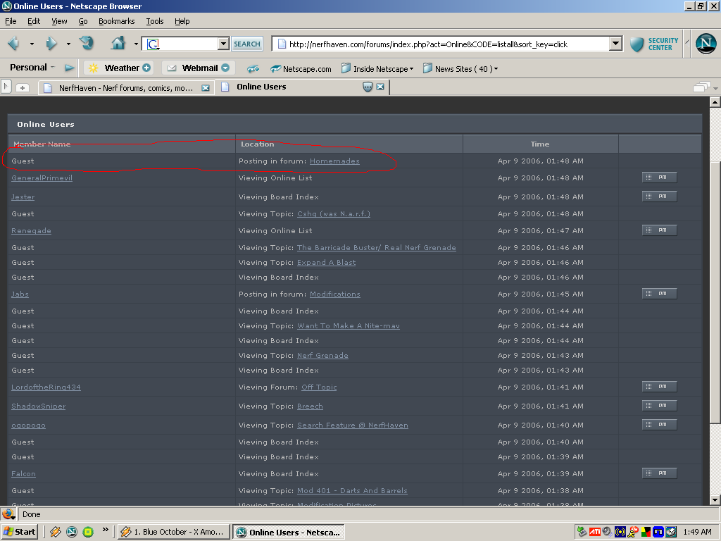
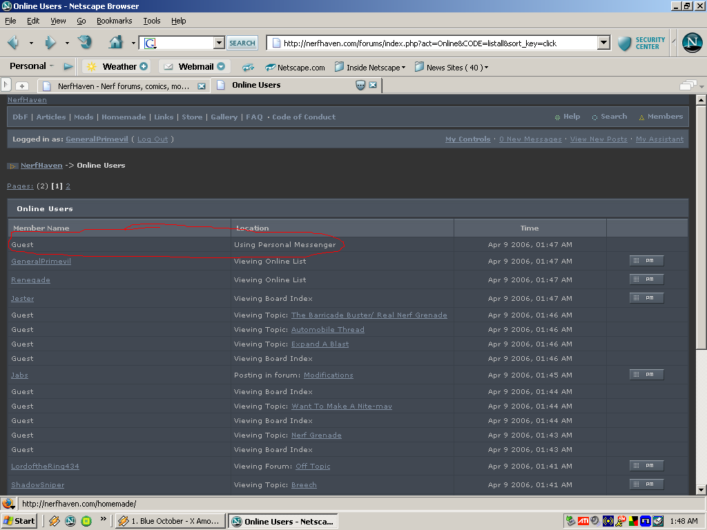
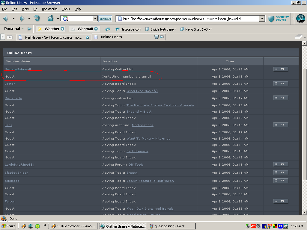
Well, since I was bored last night, I found some interesting stuff happening with the "Last Click" sorting...
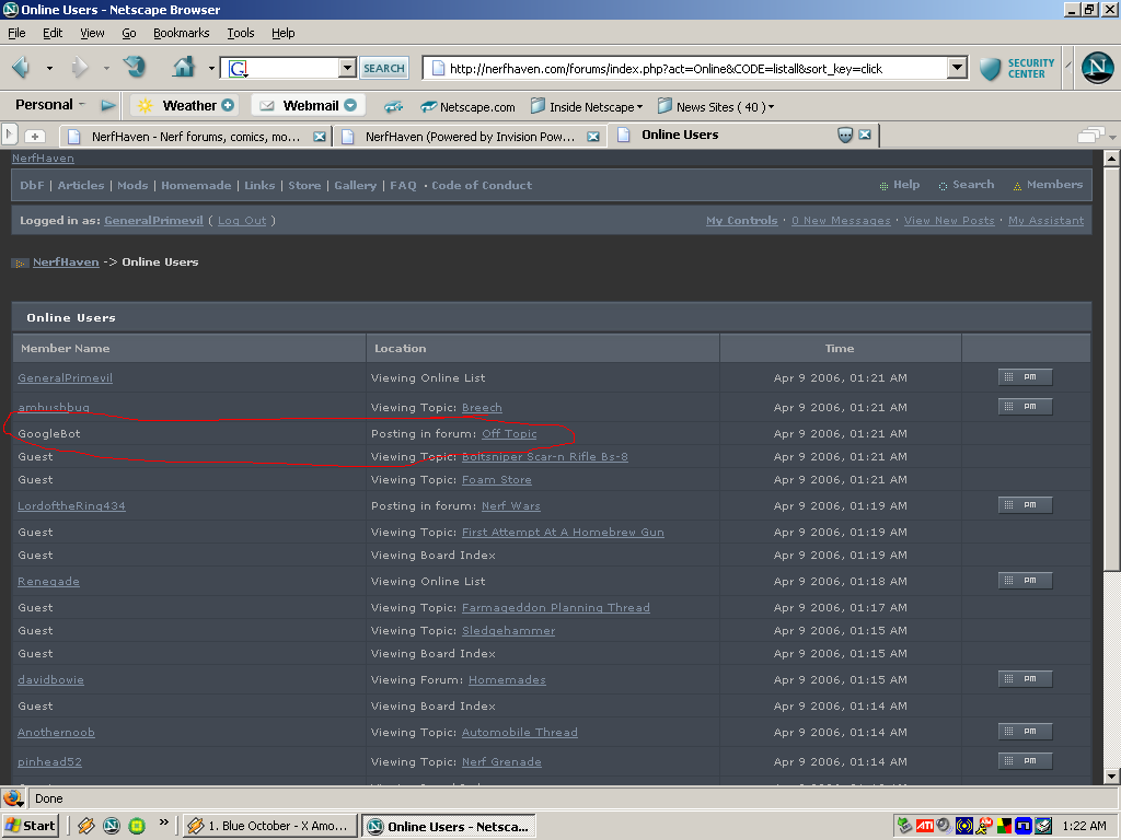
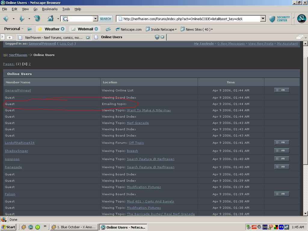
Guests can post?
Guests can PM?
A member has something in their inbox...
GoogleBot posting?
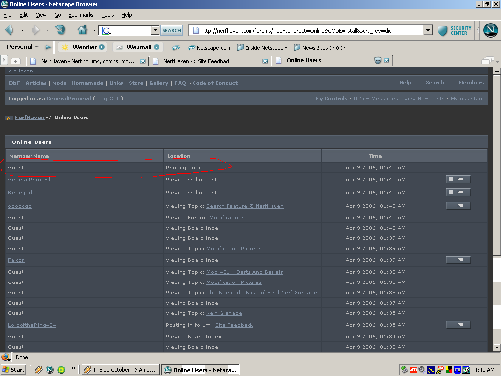
People actually print this stuff out?
I guess they wanted to tell a co-worker or something...
Dubya Tee Eff, mate, there better be some good exs-splanations regardin' some d'ose...
And, uhh, for all of those "Guest" things, there were no anonymous users on during those times.
Seriously, what is up with that shtuff?
GeneralPrimevil
Member Since 08 May 2004Offline Last Active Sep 19 2010 04:33 PM
Topics I've Started
How-to: Laser Pointer Leads
04 April 2006 - 03:17 AM
How-to: Laser Pointer Leads
Part 2: "Tadpole"
I needed to make a laser pointer have small leads on it so that I could mount it further away from where I wanted the switch. So, I real quick thought of this.
First off, you will need:
This is what I did to relocate the switch. I did not move the battery since I didn't have to; however, if you have a battery holder for two AAA, AA, A, B, C, D, don't be afraid to wire it in between the switch and the body of the laser. I'm pretty sure that if you have a holder on hand, you probably don't need my instruction on how to bypass those tw button cells.
1.) Remove both ends of the laser. No picture necessary.
2.) Remove the batteries. Also, carefully remove the sticker on the outside of the laser pointer body. Put the sticker on the coupler so that the rectangle is coplaner with a plane section perpendicular to the bases. Wrap clear tape around the information sticker to keep in in place and ledgible. If you don't remove that sticker, you life will be slightly harder since the coupler will remove it for you later.
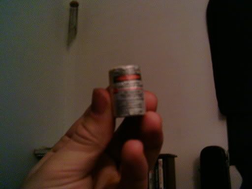
3.) Take the back cover of the pointer (the thing which holds the button cells in). Remove any key chain attachment. This is easily done with those pliers/hemostat. Now take your drill and make a 1/16" hole through this back plate. Make it anywhere as long as it goes through. See picture later down in the guide.
4.) Take a battery. Either battery. Now place in on the paperboard and trace it. Good. Now take your knife. Do not cut off a digit in this step. Cut that circle you just made to the best of your abilities. Check to make sure that it fits in the laser pointer by assembling the pointer, putting in both button cells then the paperboard, followed by the cap. More than likely, those cells will be posi-up. Make sure that the pointer does NOT turn on when you press the button. Disassemble the pointer once you make the paperboard cicle fit right. Good job, have a cookie!
5.) Take your drill bit. Make a hole the same place in the paperboard as it is in the battery endcap. Make another hole about 3/16" towards the opposite side of that hole. Make sure that neither of the holes are within 1/32" of the edge of the paperboard. Set it down where you will not lose it.
6.) Take a length of 20ga wire. Thread it through the hole in the battery endcap. Now strip the insulation off of the first 5/16" of wire. Bend it just after the insulation ends to a right angle. Thread the paperboard circle onto it. Now carefully bend the remaing wire into that other hole. If it doesn't fit, remove the paperboard, straighten the wire a bit and strip of a little bit more insulation. You may repeat that process once more after that. Any more and you will have to scrap that piece of wire.
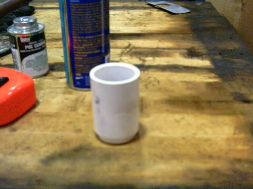
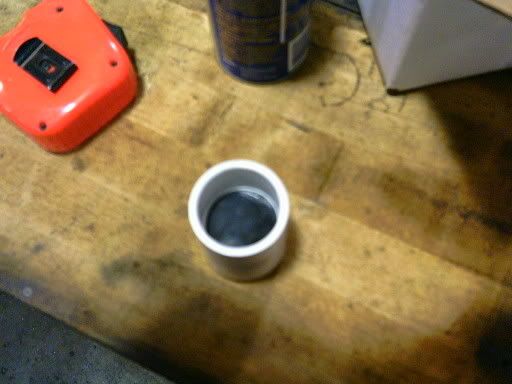
7.) You should have this now:
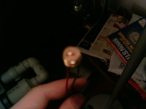
(shitty photo)
Take the empty laser pointer body. Put it through the 1/2" CPVC coupler, making sure that the button is depressed. Now take a 2.5" (roughly) length of 20ga wire and wrap it around the pointer's body, stuffing it into the coupler. This stabilizes the pointer within the coupler and keeps the button depressed. You should now have this:
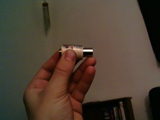
(another shitty photo)
10.) Take your other piece of wire. Strip the first 5/16" of insulation off of the wire, Now thread it through the hole on the endcap that used to have the keychain attached to it. Make the insulation be flush with the edge of the hole. Bend the wire around the keychain adapter hole.
11.) Reassemble your laser pointer. Remember the polarity of the button cells, if you still are using them. Strip the first 1/4"-5/16" of insulation from both leads (the wires sticking off the back of the pointer). Attach your connectors to these stripped ends. You should hopefully know how to use a crimp connector. Attach your switch and try it out. You may now put the protective cap back on the front of the pointer. Why did you take it off? I wanted to show you that it was pointless except to protect the emitter.
Well, it should look similar to a tadpole now:
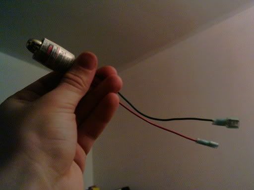
(a tadpole)
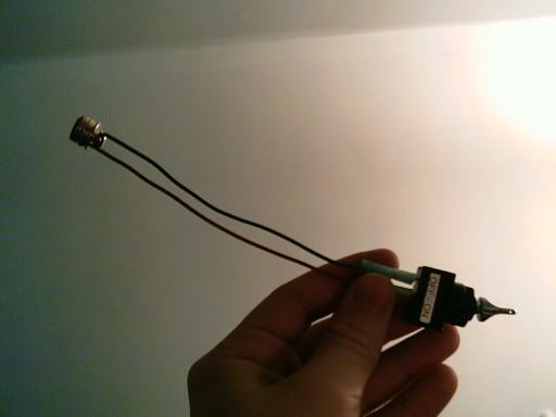
(a constant toggle switch attached via 1/4" blade connectors to the battery endcap)
I'll probably do this to a KAF member's laser pointer (a plastic Class II one, not a metal Class IIIA) and retake some of those pictures.
Questions? Comments?
Edit: the point of the coupler is to give both a surface to mount this thing using a machine screw and to keep that button depressed, since I didn't feel like soldering the connection together by removing the whole laser emittor and integrated leaf switch. If I did that, then I would've jsut made a new body for it out of 1/2" CPVC so that I could then mount it in even more places.
Part 2: "Tadpole"
I needed to make a laser pointer have small leads on it so that I could mount it further away from where I wanted the switch. So, I real quick thought of this.
First off, you will need:
- A laser pointer
- A 1/2" CPVC coupler
- A two-way electrical switch
- Two insulated crimp-style connectors which work for your switch*
- Two identical length pieces of 20 AWG electrical wire and a 2.5" length of 20 AWG electrical wire.
- Wire cutter
- Electrical wire insulation stripper
- A 1/16" drill
- A hand drill (preferred), but electric will do
- Very fine needle-nose pliers or a 6" hemostat
- Clear Tape
- Paperboard from a cereal box
- Writing tool, preferably something with a sharp, fine edge.
- Sharp, fine pointed knife, like an Xacto knife with a #11 blade.
This is what I did to relocate the switch. I did not move the battery since I didn't have to; however, if you have a battery holder for two AAA, AA, A, B, C, D, don't be afraid to wire it in between the switch and the body of the laser. I'm pretty sure that if you have a holder on hand, you probably don't need my instruction on how to bypass those tw button cells.
1.) Remove both ends of the laser. No picture necessary.
2.) Remove the batteries. Also, carefully remove the sticker on the outside of the laser pointer body. Put the sticker on the coupler so that the rectangle is coplaner with a plane section perpendicular to the bases. Wrap clear tape around the information sticker to keep in in place and ledgible. If you don't remove that sticker, you life will be slightly harder since the coupler will remove it for you later.
3.) Take the back cover of the pointer (the thing which holds the button cells in). Remove any key chain attachment. This is easily done with those pliers/hemostat. Now take your drill and make a 1/16" hole through this back plate. Make it anywhere as long as it goes through. See picture later down in the guide.
4.) Take a battery. Either battery. Now place in on the paperboard and trace it. Good. Now take your knife. Do not cut off a digit in this step. Cut that circle you just made to the best of your abilities. Check to make sure that it fits in the laser pointer by assembling the pointer, putting in both button cells then the paperboard, followed by the cap. More than likely, those cells will be posi-up. Make sure that the pointer does NOT turn on when you press the button. Disassemble the pointer once you make the paperboard cicle fit right. Good job, have a cookie!
5.) Take your drill bit. Make a hole the same place in the paperboard as it is in the battery endcap. Make another hole about 3/16" towards the opposite side of that hole. Make sure that neither of the holes are within 1/32" of the edge of the paperboard. Set it down where you will not lose it.
6.) Take a length of 20ga wire. Thread it through the hole in the battery endcap. Now strip the insulation off of the first 5/16" of wire. Bend it just after the insulation ends to a right angle. Thread the paperboard circle onto it. Now carefully bend the remaing wire into that other hole. If it doesn't fit, remove the paperboard, straighten the wire a bit and strip of a little bit more insulation. You may repeat that process once more after that. Any more and you will have to scrap that piece of wire.
7.) You should have this now:
(shitty photo)
Take the empty laser pointer body. Put it through the 1/2" CPVC coupler, making sure that the button is depressed. Now take a 2.5" (roughly) length of 20ga wire and wrap it around the pointer's body, stuffing it into the coupler. This stabilizes the pointer within the coupler and keeps the button depressed. You should now have this:
(another shitty photo)
10.) Take your other piece of wire. Strip the first 5/16" of insulation off of the wire, Now thread it through the hole on the endcap that used to have the keychain attached to it. Make the insulation be flush with the edge of the hole. Bend the wire around the keychain adapter hole.
11.) Reassemble your laser pointer. Remember the polarity of the button cells, if you still are using them. Strip the first 1/4"-5/16" of insulation from both leads (the wires sticking off the back of the pointer). Attach your connectors to these stripped ends. You should hopefully know how to use a crimp connector. Attach your switch and try it out. You may now put the protective cap back on the front of the pointer. Why did you take it off? I wanted to show you that it was pointless except to protect the emitter.
Well, it should look similar to a tadpole now:
(a tadpole)
(a constant toggle switch attached via 1/4" blade connectors to the battery endcap)
I'll probably do this to a KAF member's laser pointer (a plastic Class II one, not a metal Class IIIA) and retake some of those pictures.
Questions? Comments?
Edit: the point of the coupler is to give both a surface to mount this thing using a machine screw and to keep that button depressed, since I didn't feel like soldering the connection together by removing the whole laser emittor and integrated leaf switch. If I did that, then I would've jsut made a new body for it out of 1/2" CPVC so that I could then mount it in even more places.
Sobr-p
03 April 2006 - 11:12 PM
Well, after much deliberation, the first SOBR variant I will be punching out is going to be finished sometime this week. First off, this thing is a bullpup rifle usign parts from an AT3k, but only the valve and maybe the pump, so it is still a homemade. Now, on to why I called it what it is called, which also make up the parameters I neded to meet with the design.
Silent: I made a silencer. I deserve a cookie. In all seriousness, after making 20+ silencers in my 8 year Nerf career, I have finally developed something which works better than most (if not all). I have pictures of it later in this post. The secret to it: toilet tissue. Yes, that magical thing which seperates the Western world from the Middle East, since TP over there is too expensive for most of the poverty-stricken countries' populations to afford it. Do NOT touch their left hands, whatever you do. It's called "southpaw" for a reason. Okay, that was not meant to be offensive, unlike my new homemade.
Offensive: I needed something which would still fit my playing style: screwing with the enemy in their own base (I'm Covert Operations for a reason, people). What I mean by this is shooting them once to get them to withstand only one more shot before they are out. That is the greatest thing to do for two-shot CTF. In order to do that as undetectedly (umm...I like to make up words...) as possible, I would have to have a silent, yet compact, blaster.
Bantam: This is a synonym for short(er/ened). I wanted the gun to be less than 30", even though the spring design I have is roughly 42" in length, or the length of an M16A2 with 20" barrel. Yeah, anything from compact. That is one of the other things which lead me to make it pneumatic instead.
Rifle: It's a rifle. Duh. It could be a pistol, but I want (re: need) a rifle.
Pneumatic: This is the pneumatic version. Yes, there are two versions. One spring, one pneumatic. The spring one will start to be made after MidMI.
SOBR: Pronounced "so-ber," as in, sober, like not under the influence. I took a nice break from posting for 24 hrs. after posting a total of 26 (3 after the timestamp of a PM I received telling me I was at 23) posts within 24 hrs. Yikes...Now that I am sobered up from posting, well, I felt that one of my first posts should be about this neat project.
Well, I can not take full credit for that name. Flaming Hilt and Carbon gave me the idea with a few names they came up with.
Other info: I'm using the same breach described by a member of East Side Nerf. Google them, if you want. The gun is based off of an AT3k, since they still are available at my local Meijer and TRU. I think they may even be at my local Target. Anyway, I will be using a peculiar trigger link to get the actual trigger in front of the valve as far forward as my barrel will allow me. Pretty much, I'd like to use 10" of 1/2" CPVC as a barrel and have my trigger at the 6" mark, allowing me to put the valve 6" behind the trigger and have 6"-x"=y" behind the valve for the stock, where x=length of the valve and y=length of the 1" Sch40 PVC attached to the valve between the valve and the 90deg elbow which starts off the stock. I have a peculiar way of priming this gun, by the way, which makes this a homemade. Since I want to have a quick follow-up shot, I decided to use a tube of 1" PVC 4" long attached in front of the trigger guard as a reservoir for the firing valve. Inside that 4" of PVC, there is 125 psi of air from my air compressor (135 at MidMI), reg'd down to 20-30 psi for firing. That way, I should get at least five shots off before having to resort to a contigency plan. Anyway, the reg is attached directly to the PVC. After that, a fitting gets me from pipe threads to vinyl tubing used in Nerf guns. Now, so that I can fire without having to be near a compressed air source, I can use the stock AT3k pump to prime the chamber as well via a tee fitting I will be adding later. Oh yeah, I have a double-needle air gauge monitoring both the pre-out (reservior) and regulated (vinyl tubing) pressures. I like that gauge. It goes up to 150 psi, but I will never really be needing that high of a pressure...or will I...
So far, I have the silencer completed and have started work on the breach. I have a question for everyone before proceeding, however, which is: Is there an easier breach to make for 1/2" CPVC besides the one which a member of East Side Nerf made out of 1/2" PVC? I'm trying to attempt that with a piece of 1/2" steel pipe, since it has a slightly larger I.D.
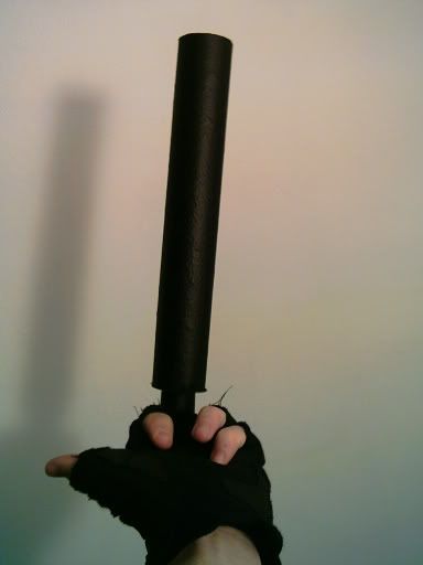
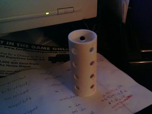
Complete Suppressor (is that picture offensive to anyone? If so, well, that was the goal of the rifle).
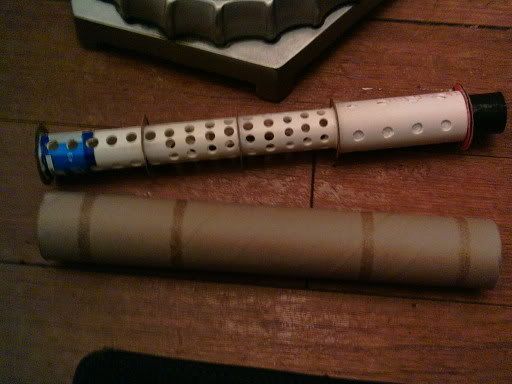
Suppressor core and sheath (prior to rubber coating)
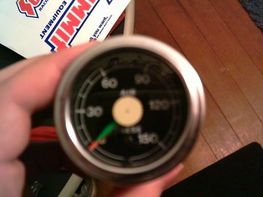
Dual needle air gauge. Schuweeet... Oh yeah, that's out of a 1973 Ford school bus. See, since we got rid of the last one of those six years ago, I figured that we wouldn't need this anymore since all of the Internationals, GMCs, and every other bus we have has remote senders and idiot lights for the airbrake systems.
More pics later (like tomorrow night). Too tired, shitty lighting, not enough components to dry-fit the thing, pick an excuse.
Anyway, questions, comments? Oh yeah, all of this stuff is not only feasable, I have done it all in previous homemades. I really don't know why I switched designs to something so simple besides the fact that I haven't owned a Nerf gun in almost a year and really need to get back to rebuilding my armory. That and well, why make a gun which takes almost a week to build when all that is left for this one is to buy a length of 1" Sch40, a 1" plug, and a 1" slip to 1/2" NPT adapter bushing.
Silent: I made a silencer. I deserve a cookie. In all seriousness, after making 20+ silencers in my 8 year Nerf career, I have finally developed something which works better than most (if not all). I have pictures of it later in this post. The secret to it: toilet tissue. Yes, that magical thing which seperates the Western world from the Middle East, since TP over there is too expensive for most of the poverty-stricken countries' populations to afford it. Do NOT touch their left hands, whatever you do. It's called "southpaw" for a reason. Okay, that was not meant to be offensive, unlike my new homemade.
Offensive: I needed something which would still fit my playing style: screwing with the enemy in their own base (I'm Covert Operations for a reason, people). What I mean by this is shooting them once to get them to withstand only one more shot before they are out. That is the greatest thing to do for two-shot CTF. In order to do that as undetectedly (umm...I like to make up words...) as possible, I would have to have a silent, yet compact, blaster.
Bantam: This is a synonym for short(er/ened). I wanted the gun to be less than 30", even though the spring design I have is roughly 42" in length, or the length of an M16A2 with 20" barrel. Yeah, anything from compact. That is one of the other things which lead me to make it pneumatic instead.
Rifle: It's a rifle. Duh. It could be a pistol, but I want (re: need) a rifle.
Pneumatic: This is the pneumatic version. Yes, there are two versions. One spring, one pneumatic. The spring one will start to be made after MidMI.
SOBR: Pronounced "so-ber," as in, sober, like not under the influence. I took a nice break from posting for 24 hrs. after posting a total of 26 (3 after the timestamp of a PM I received telling me I was at 23) posts within 24 hrs. Yikes...Now that I am sobered up from posting, well, I felt that one of my first posts should be about this neat project.
Well, I can not take full credit for that name. Flaming Hilt and Carbon gave me the idea with a few names they came up with.
Other info: I'm using the same breach described by a member of East Side Nerf. Google them, if you want. The gun is based off of an AT3k, since they still are available at my local Meijer and TRU. I think they may even be at my local Target. Anyway, I will be using a peculiar trigger link to get the actual trigger in front of the valve as far forward as my barrel will allow me. Pretty much, I'd like to use 10" of 1/2" CPVC as a barrel and have my trigger at the 6" mark, allowing me to put the valve 6" behind the trigger and have 6"-x"=y" behind the valve for the stock, where x=length of the valve and y=length of the 1" Sch40 PVC attached to the valve between the valve and the 90deg elbow which starts off the stock. I have a peculiar way of priming this gun, by the way, which makes this a homemade. Since I want to have a quick follow-up shot, I decided to use a tube of 1" PVC 4" long attached in front of the trigger guard as a reservoir for the firing valve. Inside that 4" of PVC, there is 125 psi of air from my air compressor (135 at MidMI), reg'd down to 20-30 psi for firing. That way, I should get at least five shots off before having to resort to a contigency plan. Anyway, the reg is attached directly to the PVC. After that, a fitting gets me from pipe threads to vinyl tubing used in Nerf guns. Now, so that I can fire without having to be near a compressed air source, I can use the stock AT3k pump to prime the chamber as well via a tee fitting I will be adding later. Oh yeah, I have a double-needle air gauge monitoring both the pre-out (reservior) and regulated (vinyl tubing) pressures. I like that gauge. It goes up to 150 psi, but I will never really be needing that high of a pressure...or will I...
So far, I have the silencer completed and have started work on the breach. I have a question for everyone before proceeding, however, which is: Is there an easier breach to make for 1/2" CPVC besides the one which a member of East Side Nerf made out of 1/2" PVC? I'm trying to attempt that with a piece of 1/2" steel pipe, since it has a slightly larger I.D.
Complete Suppressor (is that picture offensive to anyone? If so, well, that was the goal of the rifle).
Suppressor core and sheath (prior to rubber coating)
Dual needle air gauge. Schuweeet...
Oh yeah, that's out of a 1973 Ford school bus. See, since we got rid of the last one of those six years ago, I figured that we wouldn't need this anymore since all of the Internationals, GMCs, and every other bus we have has remote senders and idiot lights for the airbrake systems.More pics later (like tomorrow night). Too tired, shitty lighting, not enough components to dry-fit the thing, pick an excuse.
Anyway, questions, comments? Oh yeah, all of this stuff is not only feasable, I have done it all in previous homemades. I really don't know why I switched designs to something so simple besides the fact that I haven't owned a Nerf gun in almost a year and really need to get back to rebuilding my armory. That and well, why make a gun which takes almost a week to build when all that is left for this one is to buy a length of 1" Sch40, a 1" plug, and a 1" slip to 1/2" NPT adapter bushing.
How-to: Porting
31 March 2006 - 10:08 PM
One person said "Pointless" and another said "Go for it" so here it is...
How-To: Porting
Part One: "Properties of a Cylinder"
Well, a long time ago, in a galaxy not far, far away, a very artistic member of NH ranted about hole patterns (or lack there of) in homemade silencers (was it NinjZ?). Hopefully that will never happen again. There are a lot of pictures here, most taken in shit lighting, so stick with me...
This guide is to prevent one of these. Sorry about the owner of that pic, who I will keep anonymous, for using it in such a way...
First off, what you will need (to make your life easier):
1.) Start with the piece of paper. Wrap it around the pipe like so:
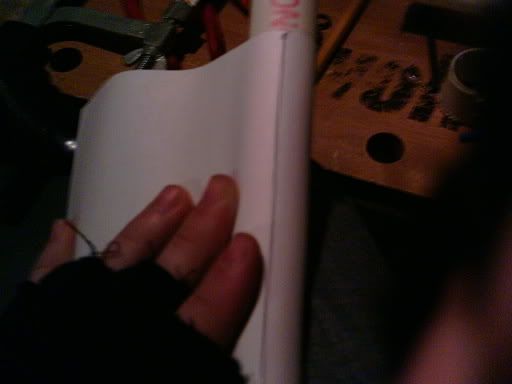
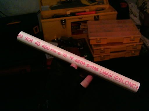
Then mark where it overlaps, like in that previous picture. That piece of office-size paper is a bit small for the length used; however, this is going to be a 12" total-length silencer made of 3/4" decade-plus-old Sch40 pipe. The pipe (cut, squared, trued, lapped, sanded slightly) is here:
2.) Now that you have that done, remove the paper and grab your indexed straight edge. Use either millimeters or inches; I prefer inches since that is on the outside of my 8-sided architectual-ruled straightedge. Measure the length you have to work with, as in, what would be the circumference of the cylinder net (width of the rectangle) you just made:
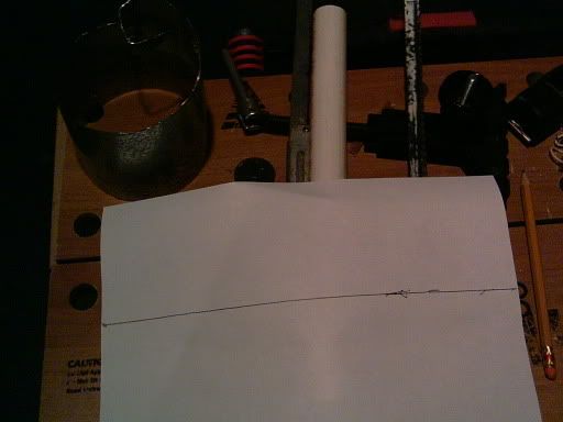
Now take that measurement, and divide by a whole number until you get a fraction/decimal which can be used for your scale. Try and make the number of holes fit with the piece; If you are making a silencer, four holes per row would be "t3h Sh!t5" since there is not enough total surface area to give any good flow. Remember to keep in mind the size of the drill you are working with; a .25" drill will not be good for a small pipe like 1/2" CPVC, unless that truly is what you need if for (two holes on opposite sides?). Write the spacing (circumference divided by number of holes) and write it down someplace. That will be needed later.
3.) Find out how much space between rows you want. I usually use twice the diameter of the drill.
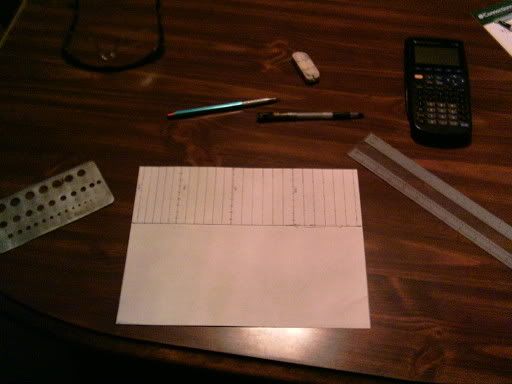
Draw lines which go parallel to where the base of the cylinder net would be, like so:
(picture coming soon)
4.)Then take that number you wrote down, and start measuring off each tic starting from the first circumferenctial line. The number of holes should be the number of tics. See here:
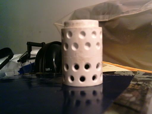
5-a.) Now, for straight lined holes, like this:
(secondary baffle for a silencer)
You simply start each row of holes at the same place. Otherwise, for spiral porting (5-b.):
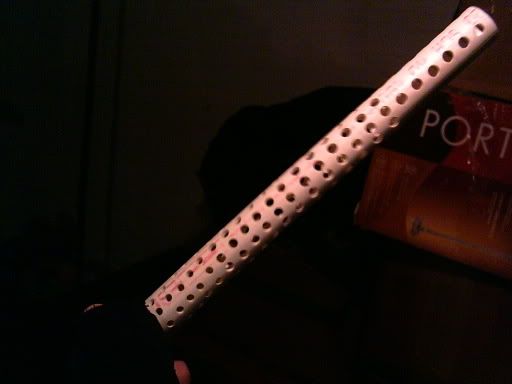
(a large suppressor core)
Or staggered porting (5-c.):
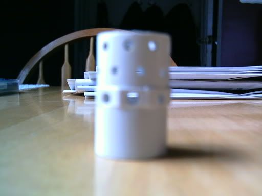
(muzzle brake)
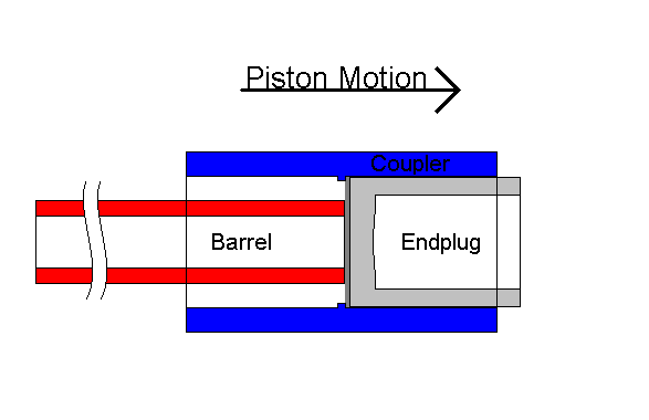
(piston for BSC-LR)
5-b.) Take that half and divide it again, starting the first row at zero, second at 1/4, third at 1/2, fourth at 3/4, and fifth at zero, etc. Then you get something similar to this:
(picture coming soon)
5-c.) Take the space between each hole and divide it in half (staggered) to start every other row:
Now, if you are just porting something for an interesting muzzle brake:
(picture coming soon)
Only use half the circumference or 3/4th or whatever and go back to step 2.
Also note that step 5-B is just an example. My silencer did not use that; every hole in a row was spaced 3/8" so I made the stagger 3/8" across 6 rows, or each row was 1/16" offset -clockwise- from the previous.
6.) Center punch each cross. Drill at the center punch indentation. Remember feed and speed rates. I was running as slow as my drill press could go (720 RPM), but should've been having the bit turn slower (400 RPM).
(need to redo video)
7.) Clean up the whole pipe, both inside and out. Use that ka-nife I listed earlier.
(need to redo video)
8.) Sand down the outside of the pipe because I told you to. Also sand the inside if it is short.
9.) Install and Enjoy! Alternatively, use 3" pipe to make a ceiling fan light cover you broke while yanking too hard on the pull switch!
(pictures coming soon)
I will probably make this go a bit smoother by removing some of the vocabulary and whatnot, but that is for a later edit. I also need to make a muzzle brake for a friend's SuperSoaker, which I will take the remaining pictures for and edit them in here. Also, I will take new video and post it. I kinda messed up due to lighting and whatnot. That and I'm too lazy to install the software to edit it...
Edit: I think this was my 400th post...wow...
Edit2: Added pics, fixed some grammer/spelling errors...
How-To: Porting
Part One: "Properties of a Cylinder"
Well, a long time ago, in a galaxy not far, far away, a very artistic member of NH ranted about hole patterns (or lack there of) in homemade silencers (was it NinjZ?). Hopefully that will never happen again. There are a lot of pictures here, most taken in shit lighting, so stick with me...
This guide is to prevent one of these. Sorry about the owner of that pic, who I will keep anonymous, for using it in such a way...
First off, what you will need (to make your life easier):
- A drill press
- Drills
- Masking tape
- A ruled straight edge
- Scissors/Paper Cutter
- A writing tool
- A piece of unlined paper
- A very sharp, very fine bladed knife (i.e. Xacto knife with #11 blade)
- A center punch
- Something round to turn into Swiss cheese
- Sandpaper
1.) Start with the piece of paper. Wrap it around the pipe like so:
Then mark where it overlaps, like in that previous picture. That piece of office-size paper is a bit small for the length used; however, this is going to be a 12" total-length silencer made of 3/4" decade-plus-old Sch40 pipe. The pipe (cut, squared, trued, lapped, sanded slightly) is here:
2.) Now that you have that done, remove the paper and grab your indexed straight edge. Use either millimeters or inches; I prefer inches since that is on the outside of my 8-sided architectual-ruled straightedge. Measure the length you have to work with, as in, what would be the circumference of the cylinder net (width of the rectangle) you just made:
Now take that measurement, and divide by a whole number until you get a fraction/decimal which can be used for your scale. Try and make the number of holes fit with the piece; If you are making a silencer, four holes per row would be "t3h Sh!t5" since there is not enough total surface area to give any good flow. Remember to keep in mind the size of the drill you are working with; a .25" drill will not be good for a small pipe like 1/2" CPVC, unless that truly is what you need if for (two holes on opposite sides?). Write the spacing (circumference divided by number of holes) and write it down someplace. That will be needed later.
3.) Find out how much space between rows you want. I usually use twice the diameter of the drill.
Draw lines which go parallel to where the base of the cylinder net would be, like so:
(picture coming soon)
4.)Then take that number you wrote down, and start measuring off each tic starting from the first circumferenctial line. The number of holes should be the number of tics. See here:
5-a.) Now, for straight lined holes, like this:
(secondary baffle for a silencer)
You simply start each row of holes at the same place. Otherwise, for spiral porting (5-b.):
(a large suppressor core)
Or staggered porting (5-c.):
(muzzle brake)
(piston for BSC-LR)
5-b.) Take that half and divide it again, starting the first row at zero, second at 1/4, third at 1/2, fourth at 3/4, and fifth at zero, etc. Then you get something similar to this:
(picture coming soon)
5-c.) Take the space between each hole and divide it in half (staggered) to start every other row:
Now, if you are just porting something for an interesting muzzle brake:
(picture coming soon)
Only use half the circumference or 3/4th or whatever and go back to step 2.
Also note that step 5-B is just an example. My silencer did not use that; every hole in a row was spaced 3/8" so I made the stagger 3/8" across 6 rows, or each row was 1/16" offset -clockwise- from the previous.
6.) Center punch each cross. Drill at the center punch indentation. Remember feed and speed rates. I was running as slow as my drill press could go (720 RPM), but should've been having the bit turn slower (400 RPM).
(need to redo video)
7.) Clean up the whole pipe, both inside and out. Use that ka-nife I listed earlier.
(need to redo video)
8.) Sand down the outside of the pipe because I told you to. Also sand the inside if it is short.
9.) Install and Enjoy! Alternatively, use 3" pipe to make a ceiling fan light cover you broke while yanking too hard on the pull switch!
(pictures coming soon)
I will probably make this go a bit smoother by removing some of the vocabulary and whatnot, but that is for a later edit. I also need to make a muzzle brake for a friend's SuperSoaker, which I will take the remaining pictures for and edit them in here. Also, I will take new video and post it. I kinda messed up due to lighting and whatnot. That and I'm too lazy to install the software to edit it...
Edit: I think this was my 400th post...wow...
Edit2: Added pics, fixed some grammer/spelling errors...
Bsc-lr
29 March 2006 - 09:07 PM
Well, I finished one of my homemades. This one utilizes a barrel sealing piston coaxial valve. I have yet to fire it, but will over the weekend (have to wait for a quarter of a cement can to set and make new Stefans). Well, on to the cannon.
First off, it is about three feet long with a 32.5" barrel. By using GGDT (made by D_Hall over at spudtech.com/forums), I was able to create some numbers. I will see how accurate my inputs were when I test it. It needs to set for three days and I finished it about two horus ago, so... Anyway, pics!
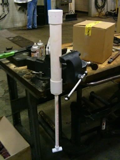
That is the chamber/valve body and barrel, suspended from a $300 lifetime warrantied vise so that the glue poured into the reducer bushing will set evenly. I poured a quarter to half inch of cement down there. I had to re-adhere the barrel after I had already cemented the whole deal to the chamber. Since it wasn't far enough in the first time, the bond had to be broken (did that within a minute) and redon. Wow, that muzzle break is really white. That's what I get for hand sanding it with 100 and 240 grit sandpaper.
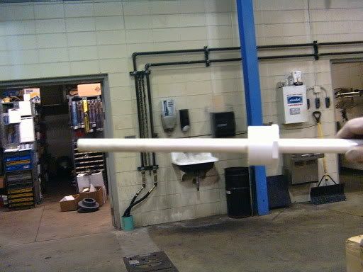
That was my first attempt at doing the bushing on the barrel. The bushing needs to be a whole 'nother two inches closer to the muzzle (the hand in that photo, which isn't mine by the way. Looks the same...).
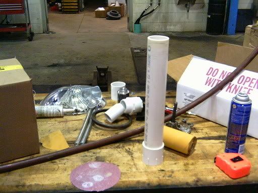
There's some random stuff with the chamber/valve body without barrel adapter and coupler attached. The coupler is behind it on the table.
That's the piston. It is made of 1 1/4" PVC fittings: a ground down bushing plug and a coupler.
There's the piston sealing face. It is made of 2.214mm thick reinforced rubber sheet, industrial super glue holds the sealing face to the piston, then it is held in securely by the ridge on the inside of the coupler. Yes, the bushing plug was put in upside down. There is a paint cross-section of the piston here.

That is the removeable pilot/fill valve. I plug it into a compressor when I need it filled, then unplug it and open the blowgun to fire it. Since the whole deal is removeable, I can breach load and/or remove the piston without having to break any joints.
Well, that's all for now. I'll edit this later with ranges and whatnot.
edit: There...I finally read all of the post again and fixed the errors and things which I messed up on the night before. Picking up the cannon today after school to let it dry at my house. Then I will charge it to 40 psi and try it out on Saturday. How many layers of cardboard would be necessary to simulate what would be ballistically safe for Nerf at a hundred or so feet? Three? Four? I'll just add more until the dart doesn't penatrate or something...
First off, it is about three feet long with a 32.5" barrel. By using GGDT (made by D_Hall over at spudtech.com/forums), I was able to create some numbers. I will see how accurate my inputs were when I test it. It needs to set for three days and I finished it about two horus ago, so... Anyway, pics!
That is the chamber/valve body and barrel, suspended from a $300 lifetime warrantied vise so that the glue poured into the reducer bushing will set evenly. I poured a quarter to half inch of cement down there. I had to re-adhere the barrel after I had already cemented the whole deal to the chamber. Since it wasn't far enough in the first time, the bond had to be broken (did that within a minute) and redon. Wow, that muzzle break is really white. That's what I get for hand sanding it with 100 and 240 grit sandpaper.
That was my first attempt at doing the bushing on the barrel. The bushing needs to be a whole 'nother two inches closer to the muzzle (the hand in that photo, which isn't mine by the way. Looks the same...).
There's some random stuff with the chamber/valve body without barrel adapter and coupler attached. The coupler is behind it on the table.
That's the piston. It is made of 1 1/4" PVC fittings: a ground down bushing plug and a coupler.
There's the piston sealing face. It is made of 2.214mm thick reinforced rubber sheet, industrial super glue holds the sealing face to the piston, then it is held in securely by the ridge on the inside of the coupler. Yes, the bushing plug was put in upside down. There is a paint cross-section of the piston here.
That is the removeable pilot/fill valve. I plug it into a compressor when I need it filled, then unplug it and open the blowgun to fire it. Since the whole deal is removeable, I can breach load and/or remove the piston without having to break any joints.
Well, that's all for now. I'll edit this later with ranges and whatnot.
edit: There...I finally read all of the post again and fixed the errors and things which I messed up on the night before. Picking up the cannon today after school to let it dry at my house. Then I will charge it to 40 psi and try it out on Saturday. How many layers of cardboard would be necessary to simulate what would be ballistically safe for Nerf at a hundred or so feet? Three? Four? I'll just add more until the dart doesn't penatrate or something...

