Jump to content


Whisper101

Member Since 30 Apr 2009
Offline Last Active Aug 26 2015 09:49 PM

Topics I've Started

FOMAS 2.0

29 July 2011 - 01:35 PM

FOMAS 2.0
Preface:
When I built the original FOMAS, I was aiming for a relatively cheap, relatively easily reproducible homemade airgun. Utilizing a modified version of Lt. Stefan’s PVAT, a Titan pump, and a rough interpretation of the templates for the L+L provided by CaptainSlug, I believe I succeeded. The FOMAS 2.0, however, was created, basically, because I saw potential in the original FOMAS to be something more than a standard “pump up the tank and pull the pin” air blaster.

Credits:
Lt. Stefan - It was his design for the PVAT and idea to somehow turn it into a functional gun that inspired me to implement it.
Ricochet - The valve connecting the airtank to the PVAT was his design. His video writeup for it is superb.

Links:
Original FOMAS - http://www.nerfrevol....php?f=9&t=2528
PVAT- http://nerfhaven.com...=1
Richochet’s valve -
McMaster - http://www.mcmaster.com/#
Ark-Plas plastics - http://www.ark-plas.com/
Parts list:
- 1x PVAT – I would recommend also getting an o-ring to help the front seal (see below for dimensions)
- 1x Ricochet’s valve (you DON’T need a barb for the side)
- 2x 4” PVC endcaps
- 13 “ of 4” PVC
- 2x 1” PVC endcaps
- 15” of 1” PVC
- 1x ¾” PVC tee, endcap
- 12” of ¾” PVC
- 1x ½’ PVC endcap, 45 degree elbow, 90 degree elbow
- 12” of ½’ PVC
- 1x ¾” CPVC endcap, 90 degree elbow, ¾” to ½” reducing coupler
- 2 pcs. Of ¾’ CPVC, one 2 1/4” and the other 1 1/4”
- 13” of ½” CPVC
- ¼” polycarbonate
- 2 ft. of 9245K51
- Metal washer- ID between 3/16” and 1/4” (either will work), and OD between 7/8” and 1” (same as before)
- 2x metal washers w/OD that fits into a ¾” tee and is held by the lip, ID just has to hold the checkvalve
- Assorted 6-32 thread screws – 2x 1”, 4x ¼”, 4x 3/8”, 1x1/2”
- Your choice of size in vinyl tubing, brass/plastic barbs (x3), and quick connect fittings (x1). I used 3/16” ID, ¼” OD tubing to increase airflow a little, but 1/8” ID tubing and fittings would work fine as well.
- LOTS of electrical tape
- 1x 13/16” OD, 5/8” ID o-ring for PVAT
- 0-100 PSI guage
- 3x check valves, only 2 have to fit your tubing size (AP19CV0012NL for 1/8”, AP19CV0018NL for 3/16”)
- 1x 3 way toggle valve (AP12SCL3SSSCL)
^^^These items can be easily sourced from Ark-PLas plastics (link in preface) for FREE. The company offers free samples, and you simply add the items to your samples cart, give them your address, and they pay for shipping to you.

TOOLS (necessary and Optional):
- Something to cut plastic tubing with (coping saw, bandsaw, crosscut/chopsaw, pipe cutters, etc) - Necessary
- Belt sander - Optional
- 6-32 tapping bit – Necessary
- Assorted drill bits – Necessary
- Drillpress or drill – Necessary (drill probably more practical for this application)
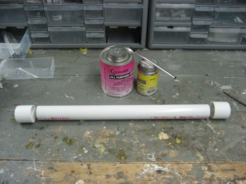
- Adhesives: superglue, PVC cement, PVC primer, epoxy putty, GOOP - ALL necessary
- Hot glue gun and hot glue - Necessary


WrIteup

PVAT and trigger
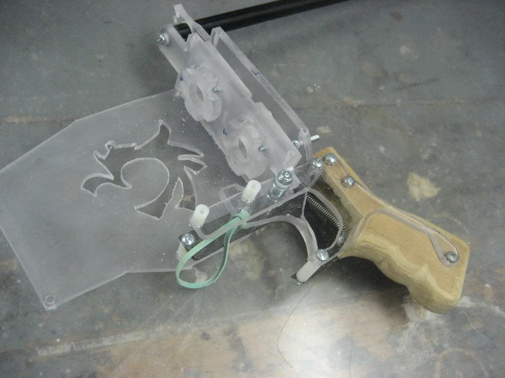
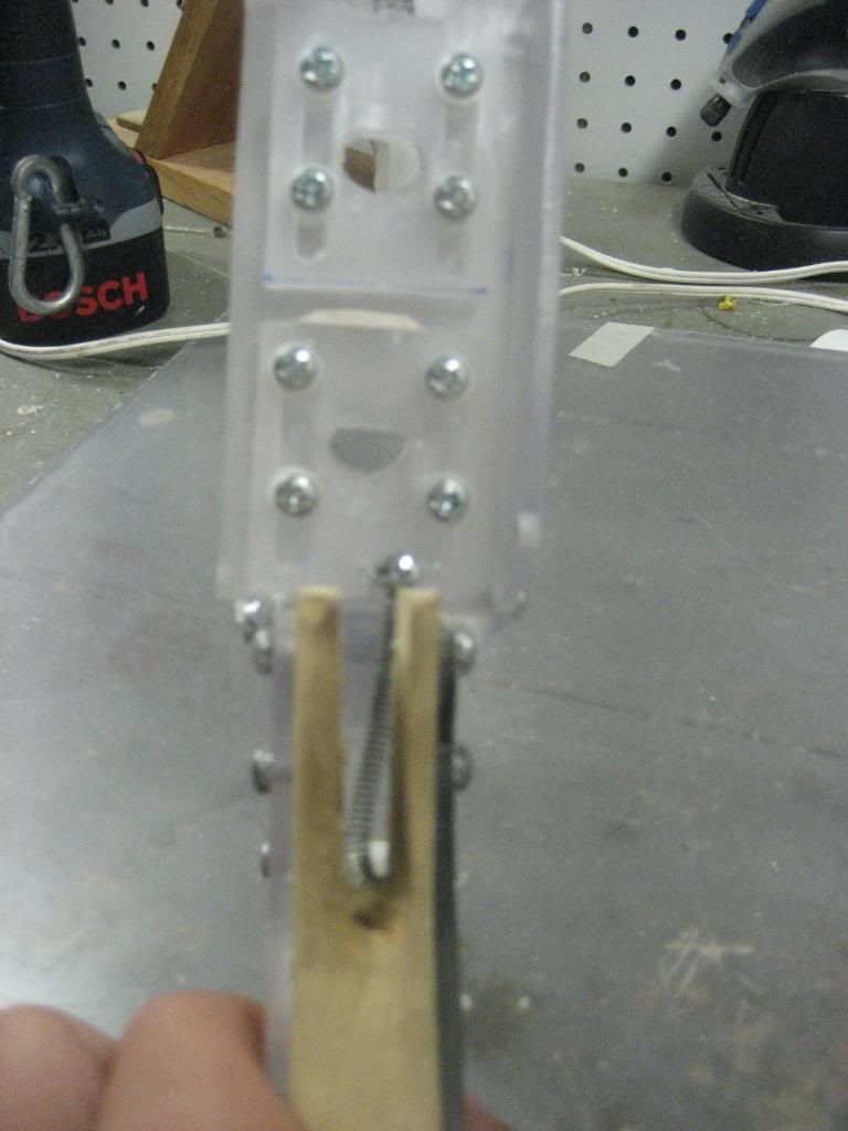
We will start with the trigger. The following picture is self explanatory. After doing this, drill a 7/64” hole through the two prongs at the bottom, thread one of the holes with your tapping bit, and enlarge the other to 5/32”.
Posted Image
Posted Image
READ BEFORE BUILDING THE PVAT:
Insert an o-ring into the front coupler part of the PVAT to help the seal
Posted Image
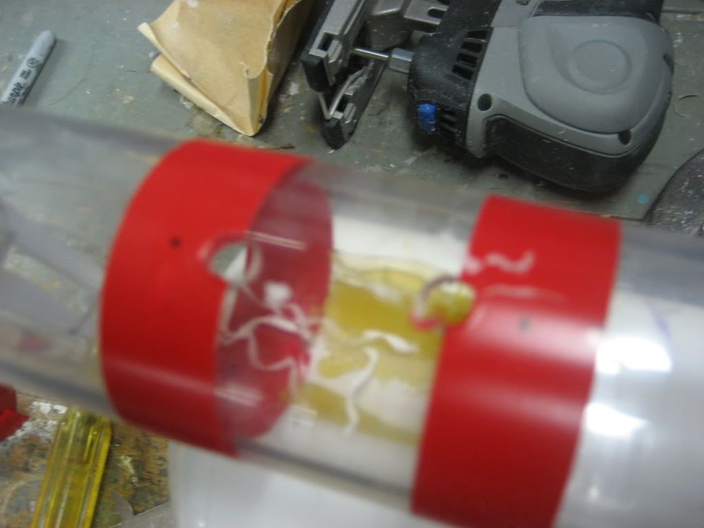
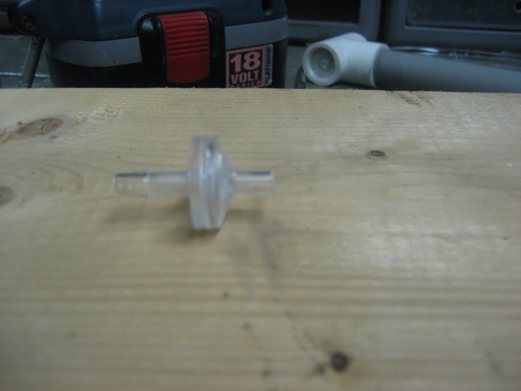
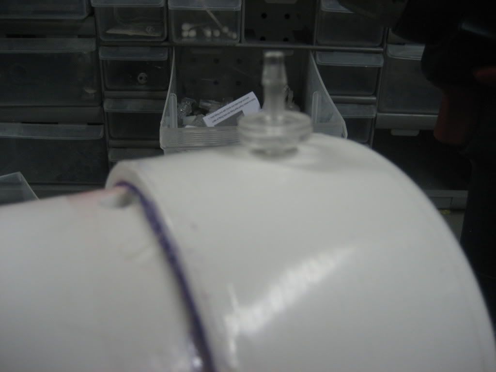
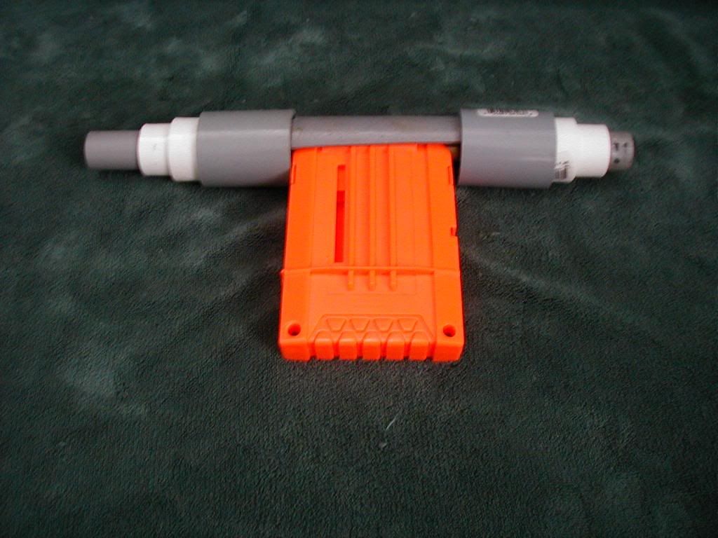
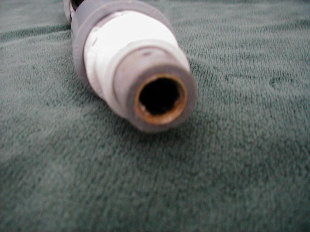
Forget the barb mentioned in the writeup. You want to end up with something like the picture below, so just drill a ¼” hole in the tank, goop 3” of your tubing in, and let it dry.
Posted Image
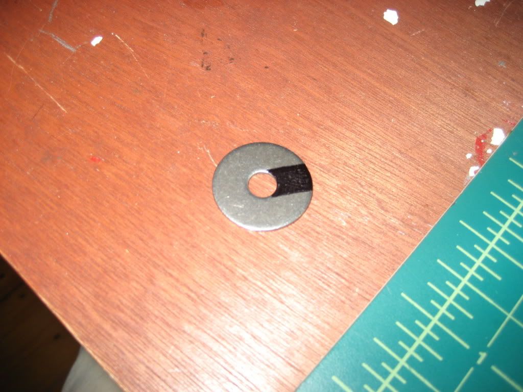
Lastly, you will want to glue a metal washer to the very end of the carriage bolt. The washer should look like this (the black part should be cut out so you can slip the washer over the shaft of the carriage bolt. This helps to increase the rate of air delivery because it enables the piston to be pulled farther over a shorter period of time.
Posted Image
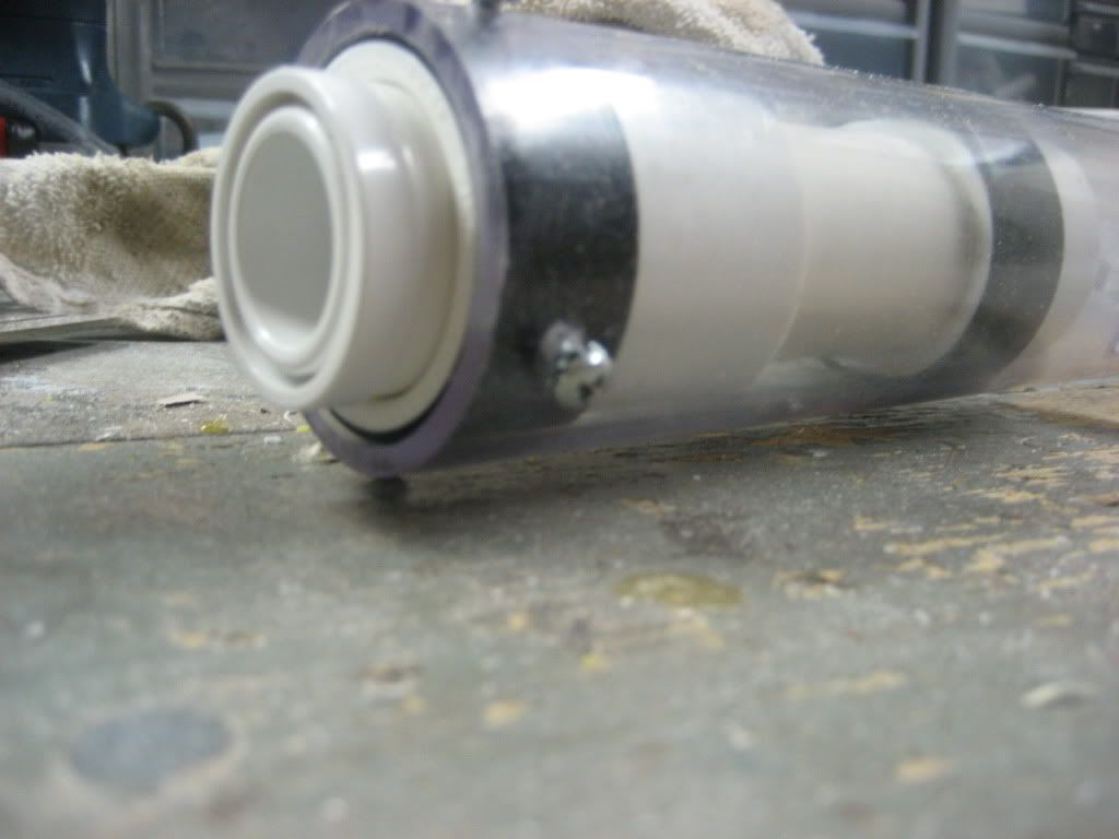
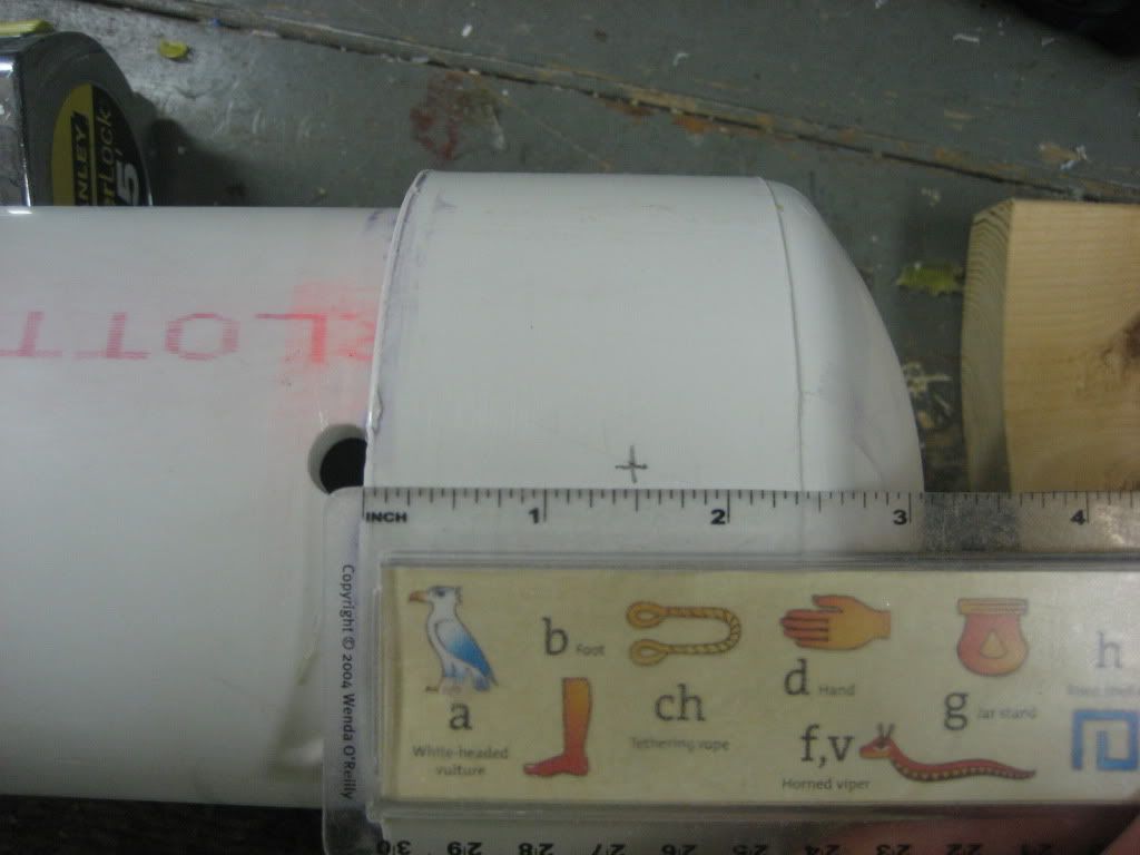
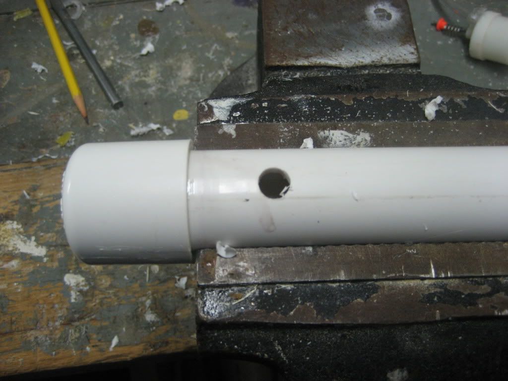
Next, wrap the PVAT in electrical tape until it fits snugly in the PETG. You want it to be snug, but also easy enough to take out when needed. Drill a hole 3 1/4” from the front of the tube at whatever angle you want the tubing to come out of the tank from. The hole needs to be large, so drill with a ½” bit and then sand it out to about the size of a penny.

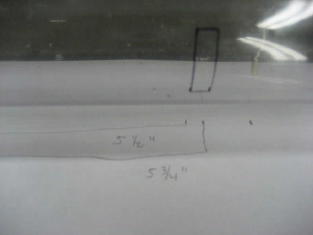
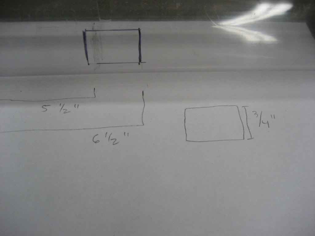
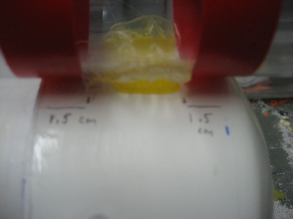
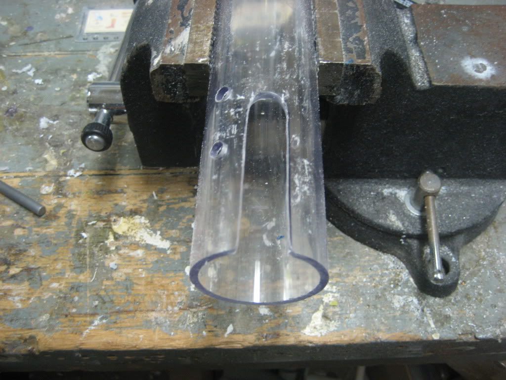
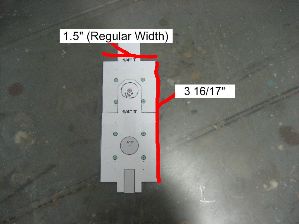
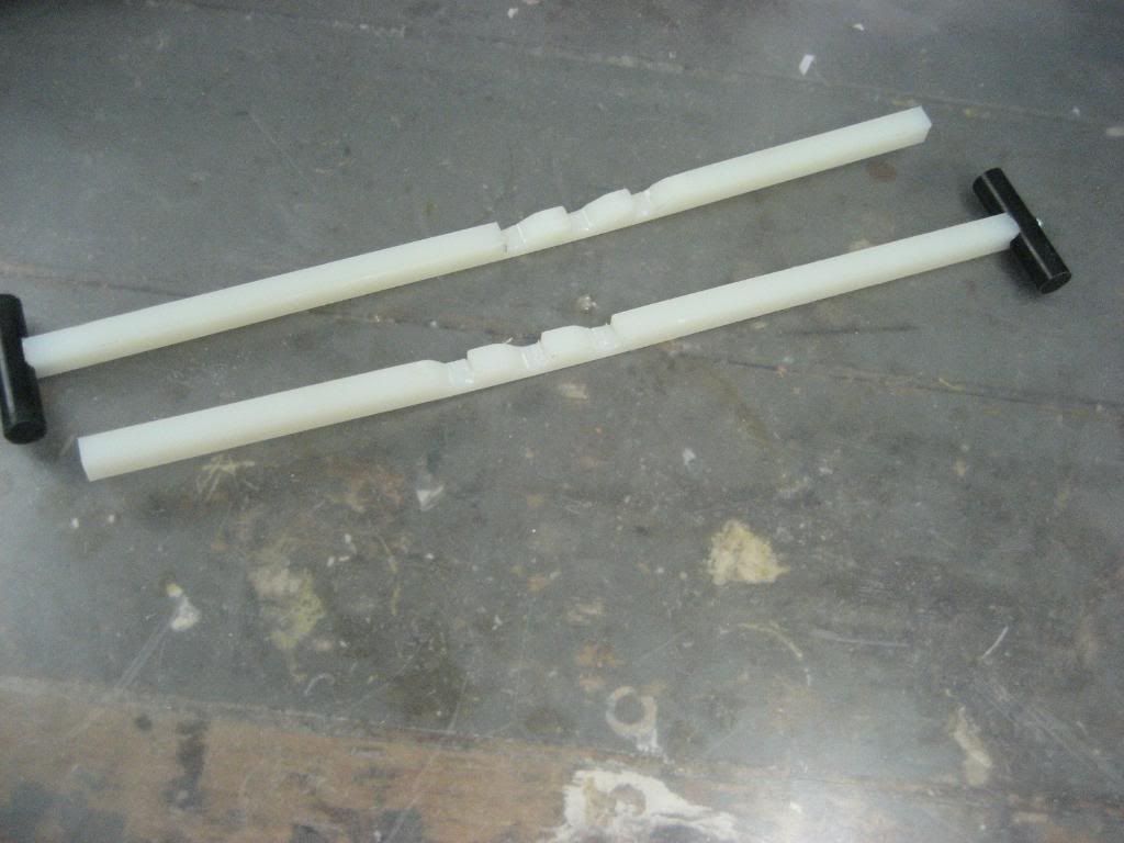
Next, take your PETG tube and cut it down to 22.5” long. As shown in the picture, measure the given lengths from the FRONT end, and cut it out. The slot is about 7/8” in width. An easy way to measure this is to measure 7/8” onto a piece of paper and then wrap it around the tube.
Posted Image
Posted Image

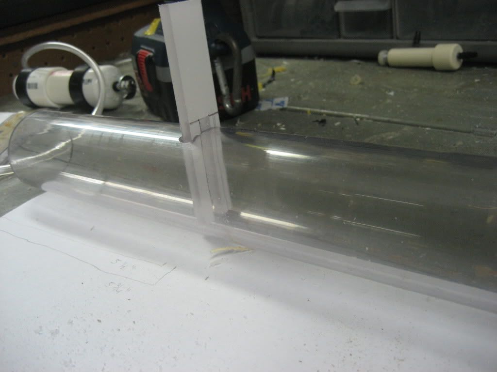
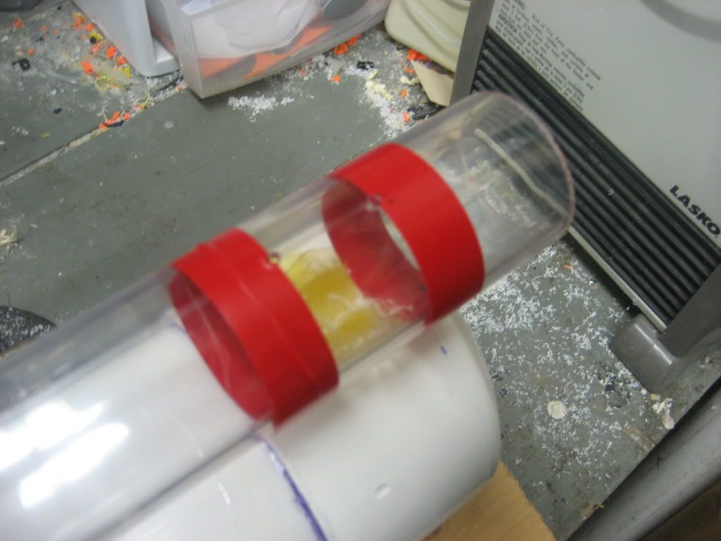
Check that your slot is the correct size by sliding the trigger into it. It should be a loose enough fit that the trigger can slide in and out easily, but it shouldn’t “rattle” around in the slot. This is the top of the tube now.
Posted Image
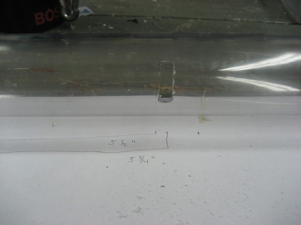
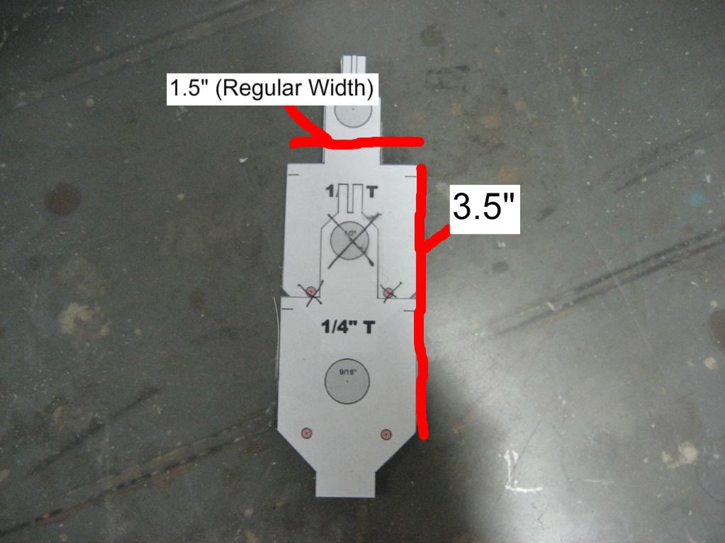
Next, mark out the given measurements on the UNDERSIDE of your tube, still at the same end as before. Cut this larger slot out.
Posted Image
Posted Image
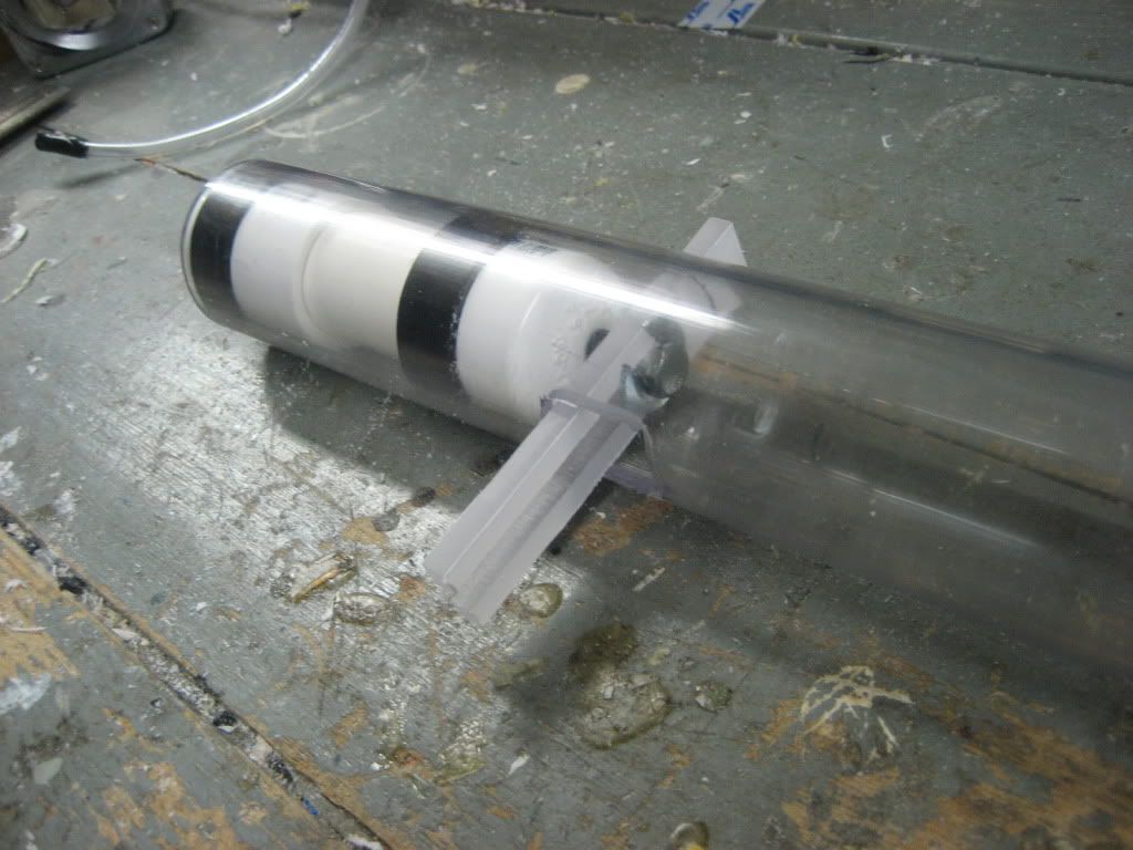
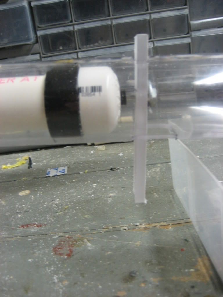
Slide the PVAT into the tube and test your trigger for fit. The two prongs should slide over the carriage bolt of the PVAT and then exit through the larger slot in the bottom.
Posted Image
Posted Image
------------------------------------------------------------------------------------------------------------------------------------------
Main Tank
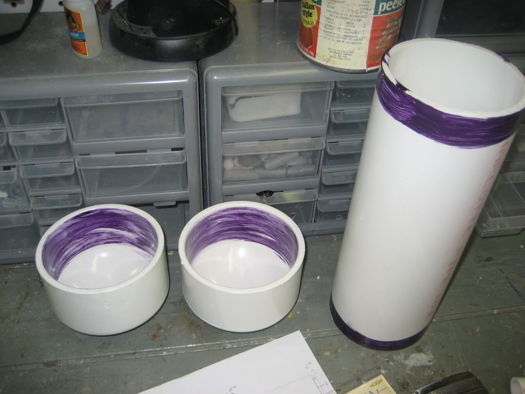
Take all of your 4” PVC components (endcaps and tube) and prime them with purple primer. Let that dry and then apply PVC cement. Slide the endcaps over the ends of the tube and let dry.
Posted Image
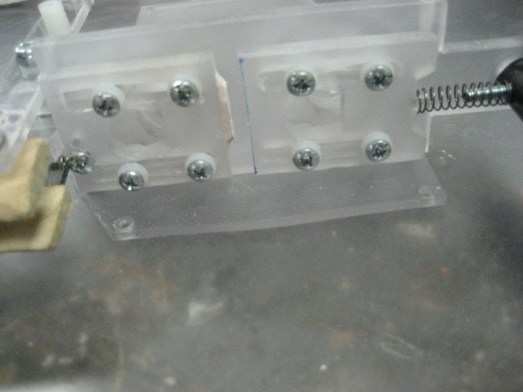
While that’s drying, insert your PVAT into the front of the tube and drill 4 7/64” holes equally spaced around the tube. Tap them with your tapping bit. Eventually, we will insert the ¼” 6-32 screws in these and tighten them down to keep the PVAT from sliding when the trigger is pulled.
Posted Image
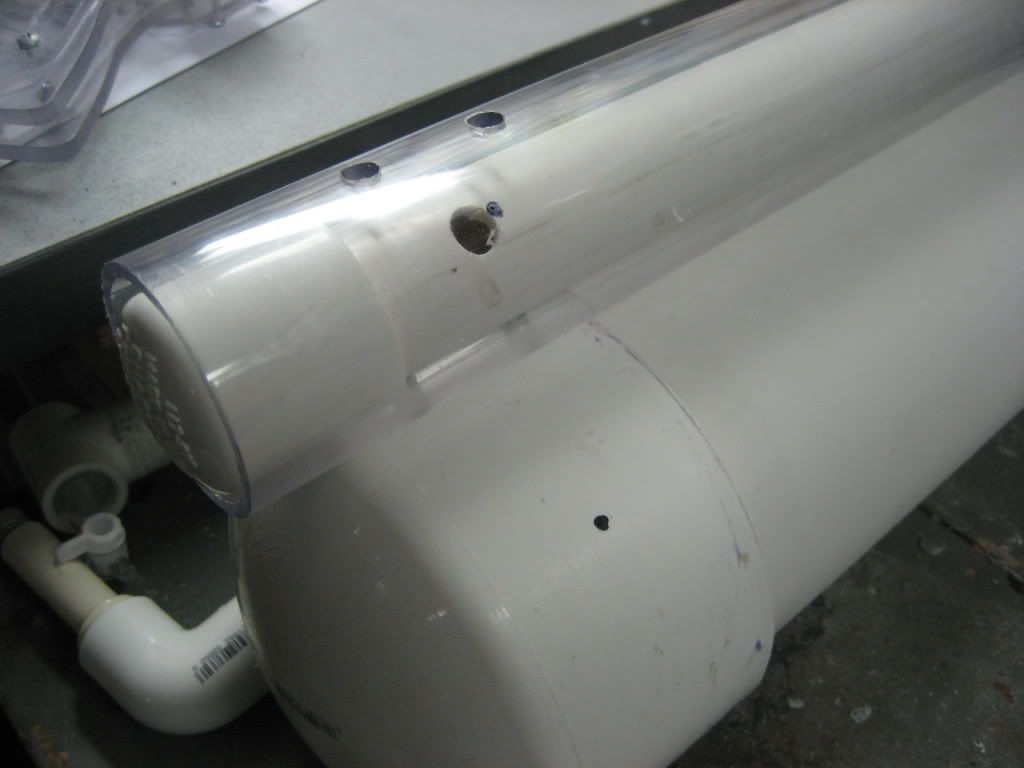
Next hot glue your tube to the 4” PVC tank so that the end of the tube and the end of the tank are square, or that they form a perpendicular line to the table.
Posted Image
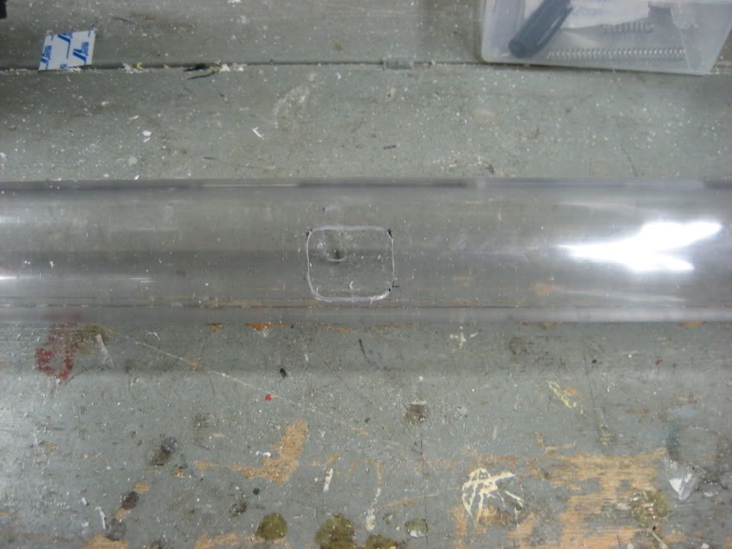
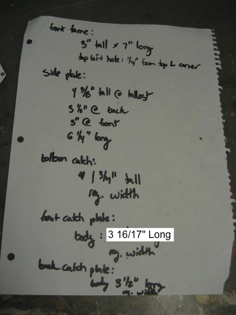
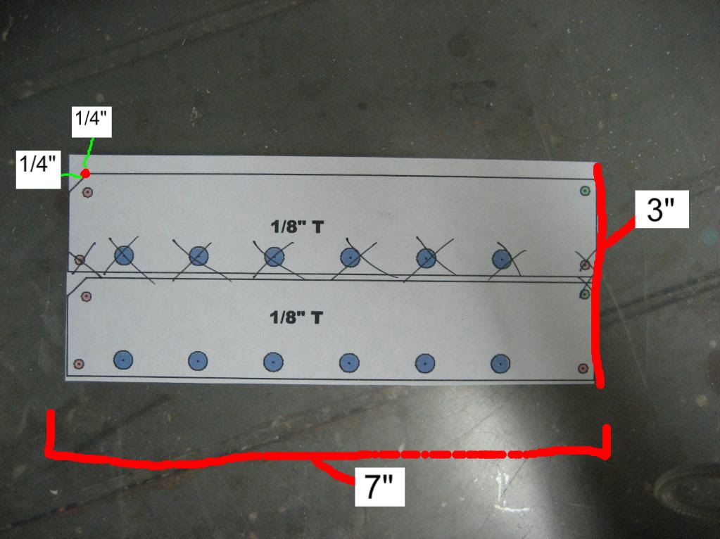
Now, set your drill bit in your drill chuck so that after drilling through the thickest part of the tube it still have about ¼” of clearance. On the front endcap, drill perpendicularly through the tube and ¼” into the PVC endcap in two places, shown below.
Posted Image
Widen the 4 top holes to 1/4”
Posted Image

Posted Image
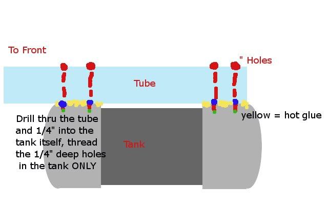
In the diagram, the 4 red dots at the top are 1/4” holes, the blue dots are 5/32” holes, and the green dots signify the original 7/64” holes. The hot glue is then removed (or left on if you want, it doesn’t matter)
------------------------------------------------------------------------------------------------------------------------------------------
Now insert the 4 3/8” long 6-32 thread screws. Make sure everything is tight and sturdy, and then disassemble the two parts.
Posted Image
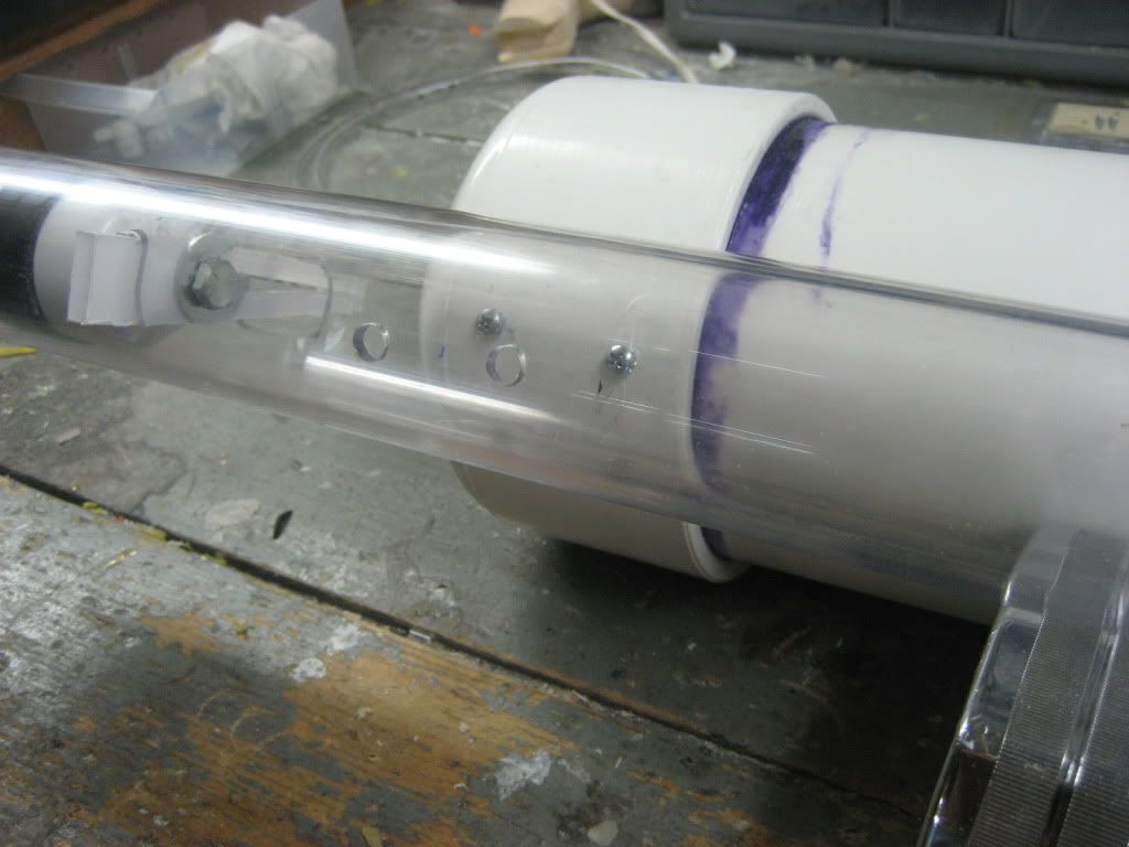
Mark and drill a hole about a ½” away from the back endcap. In the picture I drilled mine too close. It’s not a problem really, it just makes things easier later on if you drill it a little farther away.
Posted Image
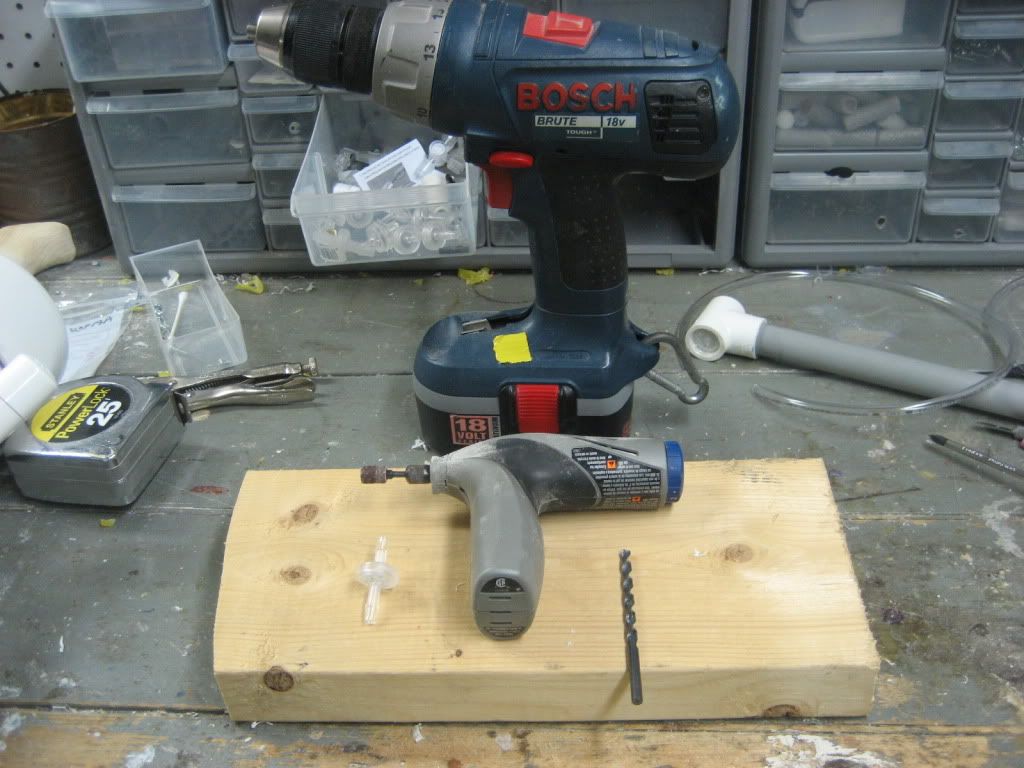
Here’s what you’ll need for this next step (that’s a dremel, a drill, a 3/16” drill bit, and a check valve):
Posted Image
Measure an inch and a half from the hole you drilled earlier (This is the one on the bottom), and drill it out with the 3/16” drill bit.
Posted Image
See how the check valve comes to a point on one side, but is flat on the other? That’s a built in arrow to signify which direction it will let air flow. Use the dremel to sand the flared portion of the nipple on the side that the arrow points to until it is flush with the “stem” of the nipple.
Posted Image
Test for fit, rough the stem with sandpaper, then superglue, solvent weld, goop, and epoxy putty it into the hole you drilled. (The picture doesn’t show the epoxy putty, but I promise I did it!)
Posted Image

2nd tank
Moving on, assemble your PVC primer and cement, as well as your 1” PVC components. Prime solvent weld, cure, blah blah blah
Posted Image
Drill a 3/8” hole 1” from the endcap
Posted Image
Pop the tank into the back end of the tube. Turn the tank so that the hole is at about 45 degree angle between the top of the tube and the tank. Posted Image
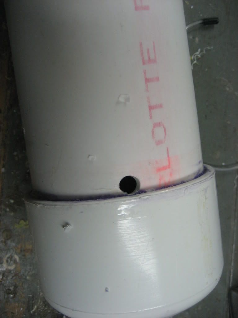
Mark the spot on the tube where the hole in the tank lies, and drill it out with a 1/2” bit, then extend the hole as shown in the picture
Posted Image
Lastly, and this is sort of a feel thing, drill a 3/8” hole on the side of the main tank you tilted the secondary tank towards
Posted Image
-----------------------------------------------------------------------

Fomas

04 March 2011 - 11:50 PM

-FOMAS-

Cool Philosophical Babble: There is a blatant lack of new, homemade air guns on this site. I could hypothesize and speculate, and generally get nothing done for days about why exactly this is, but it may just boil down to the fact that air guns are harder to make and therefore take more time to build and make work consistently. They’re in a different class from homemade springers because lines between nerf and paintball begin to blur when considering the homemade nerf air gun. Often times the air source for these guns are HPA tanks used in paintball. These and all of the fittings associated with them are expensive, and deter many people, myself included. Rather than turn away from homemade nerf airguns altogether, I set out thinking about how to make a relatively inexpensive and relatively well-performing homemade nerf air gun. I think I succeeded on both counts. As for you nitpickers, I mean the guns that have air TANKS, either pin or backpressure, so I better not get any smartasses saying, “well technically, all nerf guns are AIR guns…”. That pisses me off to no end, just like whoever said that we shouldn’t call our guns guns. Idiocy!!

Next up, a big shoutout to Lt. For inventing the PVAT, and for also jumpstarting my brain by hinting at something along the lines of this project. I thought, after having made my own PVAT and seeing it’s power and potential, that the tank itself finally had to be harnessed in the form of a gun. This is where the inspiration for this gun came from if any of you are wondering. Lt. also took the time to answer my many questions and was more than patient in helping me work out the kinks in my original PVAT.
So the general premise of the L+LPVAT is a PVAT filled L+L. I constructed the “shell” from one of the various write-ups around the haven. You will need everything except anything to do with firing of a springer L+L. For this reason, I won’t put in the write-up how to make the shell, as it is readily available elsewhere.

Places to look for additional information:
- Lt. Stefan’s PVAT writeup: http://nerfhaven.com...c=19073&hl=PVAT
- Hereticorp’s L+L writeup- no pics, but if you are literate this will help: http://nerfhaven.com...c=19073&hl=PVAT
- CaptainSlug’s partlist and template files: http://nerfhaven.com...showtopic=13999
- Slug’s guide to machining plastics as well as the tutorial on solvent welding could be useful, but only if you haven’t read them before. If you haven’t read those two guides or something more comprehensive, you shouldn’t be building this homemade.

On the topic of who this is geared towards, I would not recommend starting with this as your first homemade, or even your second, third or fourth. It’s fairly involved in cutting the “shell” parts, and getting the PVAT to seal perfectly can sometimes be a bitch. Bottom line: If you have made a polycarbonate homemade and a PVAT before, this gun is one you should be able to build.

Begin Picture Barrage:
Posted Image
Finished product- there are no in progress pics, as I never take them. Ever.
Posted Image
Posted Image
Posted Image
Trigger mech
Posted Image
Side off
Posted Image
Side off closeup
Posted Image
Posted Image
Posted Image
Posted Image
With stock
Posted Image
Stock and hopper
Posted Image
Stock and dipshit barrel, used for general jackassery when engaging in shenanigans
Posted Image
Shotgun! Oh mah gawd!!
Posted Image
Posted Image
-wait for 2nd post-

Double +bow

23 July 2010 - 07:29 PM

Before I begin this writeup, I have a few shout outs and comments I'd like to make. If you hate reading long prefaces and are more interested in the actual writeup then fine, but I'm gonna say this anyway because I think it's important.

CREDIT:

Captain Slug: For inventing the +Bow, the L+L CS, and for answering all my questions when I first began making homemades.

Louiec3 and Rogue: For coming up with the Double L+L and also for answering my questionsof which I have a lot.

McMaster Carr: Do I really need to explain why?

Split: For the discovery of the skirt seal

CaliforniaPants: For his idea of using O-rings to seal the hex bushing.

Lt. Stefan: For selling me some of his super special PVC.

Cheesypiza: For turning me onto wood handles by posting his wood handled L+L in the homemades picture thread.

Ben: He's a bit of a lurker on NRev but he did say this in response to the Double L+L:
"Wow all you need to do now is make a +bow version haha"........I hope he sees this.


Explanation:

This gun began to take shape in my mind just after Louie posted the Double L+L and Ben made that comment. +Bow catches and L+L catches are very similar and I thought that I could adapt what Louie did to fit the L+L's badass brother the +bow. I say catches because that's the key point to this gun, how the catch and firing mechanism is configured. I was right; the hardest part of the process was getting the templates right. That took some time and was frustrating as hell. After that it was smooth sailing though, just like making a regular +bow, with a few of my own personal tweaks of course! Now without further adieu, I present to you the Double +bow writeup.

1) Print out 2 sets of +bow templates, cut them out.

2) Grab both of the catches, front catch plates, back catch plates, the four sideplates , as well as all four front frame pieces

3) Combine the templates like so:
Posted Image
Here are the dimensions:
Posted Image
And now more clearly and detailed (I apologize for the crudely edited pictures. I do not have a CAD program at my disposal):
The front frame piece (you’ll obviously need 2):
Posted Image
The side plate ( again you’ll need 2):
Posted Image
The catches:
Posted Image
The front catch plate:
Posted Image
The back catch plate:
Posted Image
Those are all of the pieces that need to be modified. Any hole with a black X through it is one that I did not drill.

4) Now paste the templates on the appropriate polycarbonate pieces and cut them out.

4.5) For the second front frame piece and the side plates you can trace the piece that you already cut out onto
the protective film on the polycarbonate with a sharpie. Cut that out then line the two pieces up and use the holes that you already drilled in the first piece as a guide for the holes in the second piece.

5) Assemble! This assembles exactly like an ordinary +Bow except for the catch/fire mechanism, it just takes longer, but not twice as long as you might think! See the link to Captain Slug’s writeup in the Links section below. I have included as many in process building pictures as I can.

Here’s how the catch/firing mechanism works:

There are 2 catches. One is pushed down by a compression spring like in an ordinary +Bow. The other is held down by an extension spring like in an L+L. The extension spring is anchored both to the bottom catch as well as a hole drilled and tapped into the grip. If you were to think of the grip as a backwards L shape, you know, above where you hold the piece, the hole is drilled into the bottom of the L. If you were using a polycarbonate handle, you might think about popping an extra ¾’ machine screw through the handle to anchor the spring. The bottom catch is just tall enough so that I can prime the top gun and fire it without the bottom one being primed, I can prime the bottom gun and fire it without the top gun being primed, or I can prime both of them and shoot them in rapid succession or fire the bottom gun, walk around, and then fire the top gun. Think a double shot on lots of HGH and without the break action barrels and a lot, well, better in every way.


A list of the pieces that you will need TWO/double the amount of:

-IMPORTANT! A strong extension spring of some sort. I used ACE #71.
-[k26] spring
-Hex bushing
-12” polycarbonate tube
-2” 6-32 bolt
-6-32 lock nut
-Your choice of plunger head ( traditional dry washer, skirt seal, or grommet)
-13” plunger rod (1/2” nylon round bar or other. I used 3/8” nylon square bar.)
-Plunger tube cross
-¾” 6-32 bolts – you’ll need a total of 8
-#6 screw size Nylon washer- you’ll need a total of 16
-E-tape – you’ll need double the wraps
-ACE #61 O-rings if you choose to enhance the seal with them ( I did. )
-PATIENCE
-TIME
PICTURES!!! I’ll try to explain them as best as I can…
Posted Image
Posted Image
Posted Image
Posted Image
Posted Image
That’s right Louie, you’re not the only one who can do custom side plates!
Posted Image
The plunger rods: I used 3/8” nylon square bar because I had it on hand. It is very durable and I have not seen any signs of stress whatsoever. I changed the handles up as you will need to as well because the regular handles will not fit.
Posted Image
Posted Image

PICTURE LIMIT-DO NOT POST

Alternate +bow Plunger Tube Mat'l?

19 July 2010 - 06:59 AM

Hey all,

We all know about the evolution of the +bow and L+L plunger head, from the dry rubber washer to Split's skirt seal and now Lt.'s grommet idea which seems to solve the priciness of the +bow plunger head, but how about trying to buy polycarbonate tube in bulk? It suckas almost as bad as the skirt seal in terms of price at around $3.48 per foot. I was poking around Mcmaster online looking for something to solve this dilemma when I came across part number 8565K41. It's Butyrate tubing and it's less expensive at $11.48 for six feet. You do the math.

Anyhow, I was just wondering if anybody with a little more experience with Butyrate tubing knows or can help to figure out if it would make a suuitable plunger tube. Any and all comments and quesions are welcome. I know very little about butyrate so whatever you know will help.

Zbreech

17 February 2010 - 01:17 PM

Ok kiddies, here goes.

I recently made myself a +bow. I currentlyy love it, we are best buds 4evar, and it might possibly be the culprit of a dent in my plaster drywall. But don't tell my parents that. I noticed that the biggest problem (Which, and I think you'll agree, is pretty small) wiht the +bow is the ROF. To remedy this, I invented the Zbreech. The Zbreech is compatible with ANY blaster that is 1/2" PVC couplered. It accepts standard NERF clips, you just have to remove this tab:
Posted Image
In the picture, its already removed...

Here she is as a whole:
Posted Image
closed

Posted Image
open

[Posted ImageIMG]
still open

Posted Image
close, dammit!

http://i903.photobuc...yfarm/003-6.jpg[/IMG]
butt (this is that part that gets inserted into the coupler

Posted Image
muzzle

Posted Image
w/clip inserted

Posted Image
on my Plusbow; its intended purpose.

Posted Image
On my L+L CS, just for shits

Posted Image
On my LS undermounted Titan, just for giggles

Sorry, I don't have a picture of the Zbreech on a gun for shits AND giggles!

How it works:
The actual breech part is very similar to an angel breech in reverse. Instead of the back part of the breech moving in the angel breech, the front part of the Zbreech is extended in order to load a dart. In Mk. 1, the breech does not allow for shotgunning darts because the 17/32 brass that makes up the interior barrel, is tight enough on my darts to disallow movement. I plan to make a version using PETG in the near future too....

Not sure what else needs saying....
Oh yeah, the Zbreecj is also 100% cat-proof:
Posted Image
THERE'S a good "just for shits and giggles" pic!!!!

Questions? Comments? Flames?