Jump to content


snakerbot

Member Since 22 Apr 2009
Offline Last Active Dec 09 2023 04:38 PM

#364685 Project 13: Brushless machine pistol

Posted by snakerbot on 09 March 2022 - 02:00 PM

IMG_3933.JPG

This is Project 13. It is a brushless, stepper-bolt-driven, fully automatic, mag-in-grip pistol.


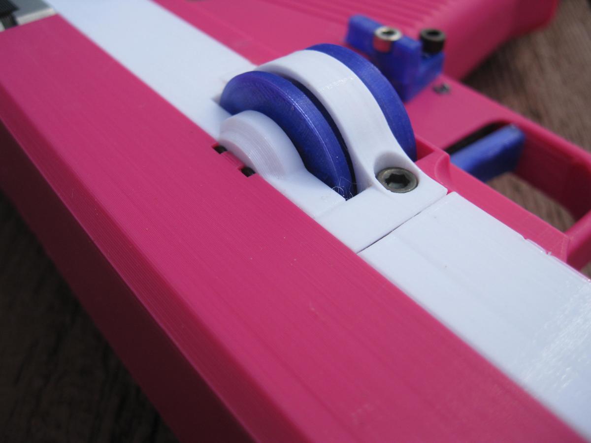
The flywheel system is built around EMax RS1108 4500KV motors. It is a Hy-con derived (circular gap) profile of 29.5mm wheel spacing and 9.0mm gap. It hits around 120-130fps with Worker Gen3s, although I’m pretty sure the long bore is interfering with the darts since just the cage was doing about 140.

IMG_3928.JPG


The pusher is a scotch yoke of 24mm stroke driven by an OMC 17HS08-1004S stepper motor and it is currently set at 8.3 darts/second. The 24mm stroke is kind of borderline with Worker Gen3s and may run into issues with 36mm darts if there’s a decap and the foam gets left behind.


The magazines are printed and are unique to this blaster, but they are very similar to angled Talons and with some modifications to the blaster I think it could take Talons.


The blaster is 246mm long and 157mm tall from the bottom of the grip to the top of the rear irons. The main body is 40mm wide, with the stepper poking out to 42.3mm, and the flywheels going out to 58.5mm. The last 26mm on the front are purely cosmetic to taper the profile down slightly. You could easily take that off and print a square-nosed version that would remove that length.


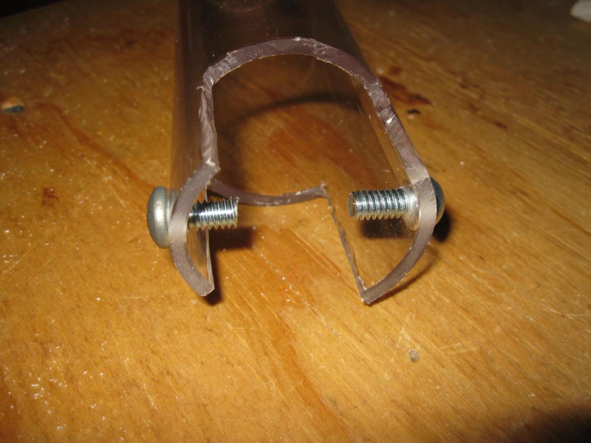
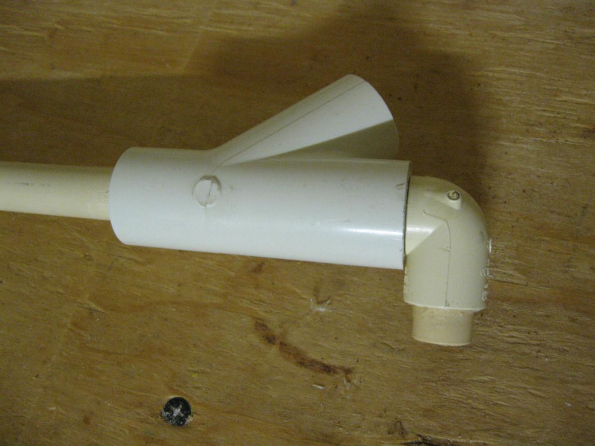
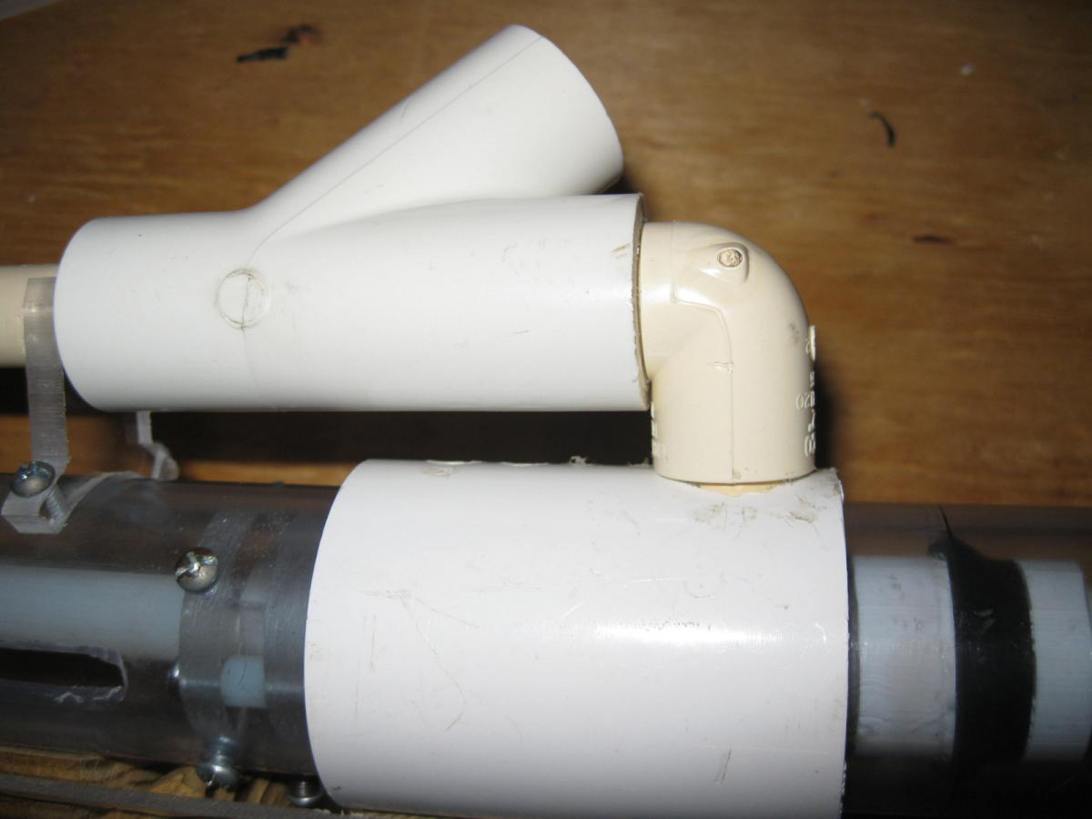
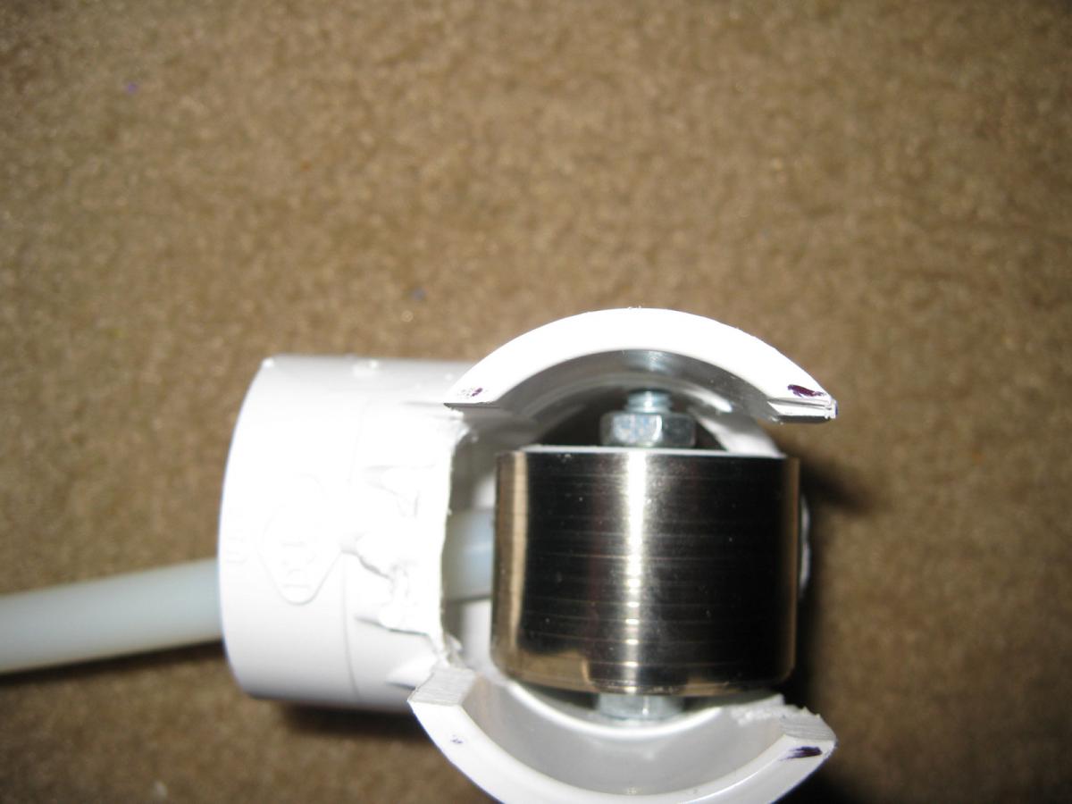
There is a detachable stock that is held in by two pins at the bottom and a spring latch at the top. These pins are 6-32 screws cut down, ground to shape, and press fit into the stock base. To remove, press the latch and rock it back slightly until the latch clears, then slide the stock mount downward. Stock is sized for 3/4” SCH40 PVC.

IMG_3927.JPG

IMG_3934.JPG

IMG_3936.JPG


The rear irons are removable, partly to facilitate printing, and partly to allow for other options to be installed. I CADed a picatinny option, but haven’t actually built it.


The battery is a Lumenier 550mAh 4s lipo.

https://www.getfpv.c...tery-xt-30.html

IMG_3941.JPG


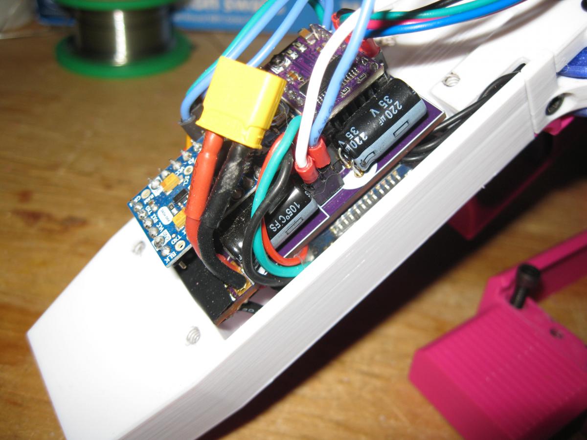
The ESCs are ZTW Spider 12A, modified with a tach wire for feed control, an upgraded DC link capacitor (Rubycon 25ZLQ180MEFC6.3X11) which has been hooked up perpendicular to the board’s long axis to shave a few mm of length. The motors are wired directly to the ESCs, without connectors, to save more space. The blaster’s main PCB is a custom unit. It takes an Arduino Pro Mini and a DRV8825 carrier board and features headers for the ESC signal cables, trigger, and bolt limit switch, but no other controls. I had to use short headers to fit the connections under the top cover. This board is also used for power distribution to shave a little space and not require splices in the wiring. Battery lead goes to one of the two sets of holes on the side, and ESCs get wired directly to the other sets (ESCs go on the symmetrical pairs). There is bare copper on both sides of the board so you can dump solder on the pad or add bus bars for Vbus and GND. Remember to put something on the board to insulate these bare areas.

IMG_3947.JPG

IMG_3943.JPG


The trigger switch is a full sized microswitch, with the solder tabs cut way down so it fits between the trigger and the magwell. I also cut a notch into the top corner of the body to pass a wire through.

IMG_3931.JPG


As with a lot of my recent work I should credit torukmakto4. While this shares no parts with any of his designs, many of the ideas have root in those designs. This obviously looks a lot like the ACS but much of that (though not all) is convergent evolution, not direct inspiration. And the software is largely his work as well. Also thanks to Matthew Bregg for bringing the ZTW Spider 12A to my attention.


CAD, firmware, and Gerbers in https://drive.google...Iv5?usp=sharing


Filaments are Overture magenta, Esun white, and Yoyi transparent violet. The magazine pictured is Overture transparent with a magenta follower.


Errata and other notes:

- The file I provide here for the upper is what I printed, but it required rework after the fact. It needed to have some deeper pockets cut into the corners of the stepper recess to fit it.

- I forgot to add a pocket on the stock base for the latch spring to match the pocket in the latch. I just drilled a hole here on my printed copy.

- Most screws are 6-32, with a couple exceptions. Motor screws are m2, stepper mount screws are m3, there is an m3 in the mag release due to space constraints, and there is a 4-40 set screw in the crank for the same reason.

- The spring on the stock latch was taken from my parts box so I have no part number to provide.

- I can confirm bs_nfet firmware on the 12A version of the ZTW Spiders, and also that the portable chromium install and rapidflash method that Matthew Bregg detailed at https://torukmakto4....or-flyshot.html works for them.

- In the one game I used it in so far, it was horribly inaccurate, although I’m not sure how much of that was the blaster and how much was the darts (used Worker Gen3s), or me, or the 20mph wind that day. This may be the bore interference again.

- Some more notes on the magazines: As I mentioned they are very similar to angled Talons. I originally intended this to take angled Talons but as I thought about it I realized I’m designing this blaster for me, not anyone else. I don’t already have an infrastructure around angled Talons and would be printing my magazines anyway, so I felt comfortable making more changes than I originally planned. These magazines have the same overall external dimensions, although they’re just rectangles and don’t have the notches on the front and back that angled Talons do. And because they print outsides on the bed the feed lips don’t protrude beyond the body dimensions. The front edge just under where the dart gets pushed out is slightly lower down here to accommodate a bit of flywheel cage geometry. And finally, they have a front catch notch. To make this blaster compatible with angled Talons, the following changes would need to be made:

  • Pocket out the opening to allow the feed lips to fit. I don’t know what this would do for strength.
  • Remove the offending geometry from the flywheel cage area on the lower or alternatively grind that part out of the magazines.
  • Make some sort of rear magazine catch or add a front notch to each magazine.

  • 1


#364637 Clarification of differences between Hoppers, RSCBs, Choppers, and BRI

Posted by snakerbot on 25 May 2021 - 08:43 AM

RSCB

I forget what this stands for, I think it's an acronym of people's names.


I heard it standing for Rawray7, ShortShit, Cynical Synapses, and 3DBBQ.


  • 2


#364600 Project 12: 100% brushless Vortex blaster

Posted by snakerbot on 16 August 2020 - 11:59 AM

IMG_3867.JPG


No, I’m not skipping all the odd numbers. My projects are numbered by when I start working on them, not when I finish. And Project 9 and Project 11 have both hit snags, so here we are.

Project 12 is a 3D printed, brushless flywheel, fully-automatic Vortex blaster. As with Project 8, it draws on the work torukmakto4 did on his T19, but where Project 8 was basically a T19 in a different body, this is much more different. As general highlights, Project 12:

  • Features a brushless outrunner based direct drive bolt. No steppers, DC motors, gearboxes, or solenoids.

  • Has only one powered flywheel, like the Nitron.

  • Has a Turnigy V-Spec 2205 motor for the flywheel drive.

  • Uses an Afro 20FS ESC for the flywheel drive, and an Afro 30FS for the bolt drive.

  • Uses torukmakto4’s Flyshot protocol to set the flywheel speed.

  • Uses torukmakto4’s tach-based single-trigger control that measures flywheel speed in real time and fires when it is up to speed.

  • Can carry a spare magazine in the stock

It is large and very heavy. Somewhat larger than it needs to be, with the muzzle extension and foregrip, but I wanted it to feel like a Nitron. I initially tried it with two powered flywheels instead of an idler because I thought that would give me more control of the disks’ trajectories, and for a little while I thought that maybe I could get more velocity out of it by pushing both sides. Neither of these worked. At the end of all this, the disk trajectory still isn’t as consistent as that of the Nitron. I tried various wheel speeds, flywheel gaps (currently set at 33mm to roughly match the Nitron), and various amounts of control bore, primarily by using printed sleeves to narrow down the bore. I also tried using a non-rotating idler, which fired fine, but didn’t really give any advantage. It currently features a 38mmOD powered flywheel and a 36mm OD idler on 70mm center-center spacing. I’m curious if that softer elastomer rim on the Nitron flywheel is important.


It’s having some reliability issues, but only with Pyragon drums. I’m not 100% sure what’s going on here. Might be just because it’s firing so much faster than the Nitron and the drums can’t keep up. 20 round stick mags are fine. I’m waiting for the chance to combat test this to see how it works there before I spend too much more time on it.


Printed in Snolabs red, Reicher blue, and black amethyst petg. Weird mixed bag of qualities here. The red is very good, the black amethyst is very stringy, but also has perhaps the best surface finish of any filament I’ve ever used, and the blue is terrible, with a diameter that varies so much I can see the effects in the finished parts.


Let’s talk more about the bolt drive, since that’s the big piece of new tech here. It uses a QXMotor QM5006, which despite the name, I think is actually a 4106 sized motor. It is 24N28P, with a KV of 350. It is 48mm in diameter, 20mm tall, and has a mass of 90gm. That really is what I was going for here. I’ve had good history with the stepper on Project 8, but steppers are heavy, at ~400gm. Cutting 310gm would reduce the mass of Project 8 by something like 15% on its own and partially cancel out the added mass on Project 12 of printing much more robustly, making just a bigger blaster overall, and adding a crapton of mass with a Pyragon drum. It’s expensive though, and behaves a little oddly at the moment. More on that later.


It uses a custom tuned version of SimonK on the ESC to enable forward/reverse operation and motor braking. I also played around with the throttle pulse widths to better match up with what I was able to get from the ATMega8 on the Arduino. I am using the governor to set the RPM of this motor, not Flyshot, since Flyshot is not currently compatible with the variable throttle needed to get forward/reverse operation, deceleration, etc. that I needed for this to work. I may play around with this and try making new version of it, but it’s not a high priority for me right now.


On the Arduino side, I’m using a Pro Mini and the AVR’s Timer2 to get a 488Hz hardware PWM for the throttle signal to the bolt drive ESC. Now that I’m only using one flywheel drive, I could use the other Timer1 channel there to drive the bolt, but I programmed this with the intent to use two powered flywheels, so the bolt motor had to get its throttle signal from a different timer. With that timer and the pulse width ranges set in SimonK, I have 2% resolution on the throttle signal. The codebase is essentially torukmakto4’s S-Core 0.96, with various changes for my use:

  • I changed the pinouts to work with my hand-wired board.

  • I got rid of the variable speed flywheel drive handling code and just set it once at boot time.

  • I got rid of select fire code, although I kind of flipped back and forth between blowing it away completely and just setting it to full auto all the time, so it’s a huge mess. There’s definitely a ton of useless code in there now that I should probably get rid of.

  • Obviously, the changes to use the outrunner bolt drive.

If you just want to see what I did to make the bolt drive work, look at the following functions:

  • fire(), decelerateBoltToSwitch(), and reverseBoltToSwitch(), for obvious reasons.

  • setup(), for enabling the Timer2 hardware PWM signal.

  • die(int major, int minor), because without a stepper to make error code noises with, I had to handle them some other way. I settled on broadcasting them through the serial monitor.

Because the bolt motor is brushless and I retain all the fire control logic from S-core, the bolt is stall- and jam-resistant. It will self-home at boot and reverse if at any time it fails to reach its goal by going forward.


There are a couple weird things about how it works though. First is that the typical math for setting the governor (described in https://torukmakto4....loop-speed.html) just doesn’t work with this motor. Right now my TIMING_MAX is 0x0BE4, which should be 938RPM, but I’m actually getting more like 730. No idea why this is.


Second is that I had this running like clockwork on a testbed that consisted of just the motor, bolt, and associated electronics, but as soon as I put in in the blaster, everything went kind of wonky. I’m getting a lot of double-fires when I try to single, and a relatively slow tap tap tap of the trigger often gives me a sort of bursty type firing of a bunch of shots. I’m going to continue to play around with the code, try adjusting the position of the limit switch, etc, and see what I can find, but I’m also putting this out there so if anyone with more time and/or programming experience than me wants to take a look at it, they’re welcome to.


I mentioned that I tried having both wheels spin at different speeds. That took some code changes to work with flyshot, so I put another version of the code up (in the misc folder) in case anyone wants it. For how I did that, see, primarily:

  • setGovernorBoth (void)

  • updateSpeedFixed (void)

  • ISR(TIMER1_COMPA_vect)

Although there are various other places where it comes into play, like variable definitions, and bits of loop().


Anyway, files are all in my google drive if you want to see my code, or try making one of these yourself.

https://drive.google...PID?usp=sharing


IMG_3868.JPG

IMG_3869.JPG

IMG_3870.JPG

IMG_3872.JPG

IMG_3873.JPG


  • 1


#364497 Smaller caliber darts?

Posted by snakerbot on 11 March 2020 - 09:46 PM

Way back in the day (like 15+ years ago) Some people experimented with 3/8" darts but they never came to anything.


  • 1


#364354 Ballzooka 94 mod

Posted by snakerbot on 21 December 2019 - 11:00 PM

The only mod writeup I've ever seen for that blaster is the one I did. I'm not sure it's a great mod, but it exists.


To answer your questions, it's a manual plunger blaster, sometimes called  "push-pull" blaster, for obvious reasons. Lately I've seen this style of blaster called HAMPs, after Kane's blaster of that name. I'm not sure about extending the inline clips. I've never seen it done.


  • 1


#364350 Houston Area Nerfers Unite (HANU) Monthly War #35

Posted by snakerbot on 20 December 2019 - 08:39 PM

We have these every month, I just forget to post them most of the time. Unless otherwise noted, they are the first Saturday of the month, at 10:00 AM, at this location.


Date: Saturday, January 4, 2020

Time: 10:00 AM until 2:00 or so.

Location: Hilton C. Schott Park, 8510 Will Clayton Drive Humble, TX 77396

Take the entrance farthest west, closest to 59, by the big red and yellow playground setup (A) and go all the way to the back. We'll be set up around the gazebo/picnic table (B).


Schott park labelled.png


Rules:

150fps limit.

Stock or stock-ish ammo only. Workers, Artifacts, and other short darts allowed as long as they have soft, stock-ish tips. No FVJs or voberries. There will be a community ammo bin which is mostly full of accufakes, waffles, and elites.

No blasters with realistic looking paint jobs.

All ages welcome, but if you aren't old enough to drive yourself, someone who is needs to stay with you.

Eye protection of some sort is mandatory.


Gametypes:

A mix of deathmatch and objective based games. A typical day might look something like this:

- 3-15 teams

- Territories

- CTF

- Carpe

- VIP

- 3-15 pistols


We're on Meetup and Facebook as well.

https://www.meetup.c...ents/267320334/

https://www.facebook...49451813/?ti=as


  • 1


#364046 Project 10

Posted by snakerbot on 05 July 2019 - 06:29 PM

IMG_3823.JPG


Back in December 2012, I made what was then my second homemade, an extension spring powered, bullpup rainbow (later named by Vaan as an ESRB, so that’s what I’ll call it).


And while it took a few revisions before it was truly reliable, that blaster has remained in service at the high-velocity games I’ve played at more or less continuously since then. Though it served me very well, a few niggles started to bug me:


- The barrel wasn’t quite on straight.

- The wooden handle had spent the last six-and-a-bit years absorbing water from the humid Houston air and was splitting.

- The screws holding the handle on no longer were staying tight.

- The trigger flopped around.

- General jankyness resulting from my lack of skill in 2012.


So earlier this year I set out to make essentially a 1:1 replacement for that blaster, intended to address the above issues. I had also hoped that I could improve the efficiency of the blaster by 3D printing a redirect piece with a smoother airflow path, using a lighter plunger rod, etc., but this new one is chrono’ing at basically the same FPS as the ESRB (around 230 with sweet oranges), so I don’t know if any of that stuff worked.


As with the ESRB, I don’t intend this to be a fully fledged writeup. Those of you with the experience and tools necessary to make this can probably figure out just from the STEP file what to do.


A couple notes though.


- This uses the same 1/4” galvanized aluminum plunger rod as Ryan and Kane used on the later version ESLTs, but with a 3D printed piece added on to enable rainbow catch usage.

IMG_3827.JPG

- This also uses the same o-ring plunger padding method as the ESLTs.

IMG_3835.JPG

- As with the ESRB, this uses a U-Cup to seal the plunger rod in the redirect, but it’s a different part number since the rod is a different diameter. This U-Cup seems to be adding a bit of friction, so I have an o-ring I’ll try eventually.

- The hopper wye has had the top corner shaved down to give the darts a little more room to maneuver the corner, and this uses a brithop. In my experience this is the most reliable method of shooting sweet orange darts.

IMG_3841.JPG

- I’m using one of LegoDEI’s rifling attachments on the front. The STEP file just features a dummy piece there.

IMG_3830.JPG

- The purple printed wye support is different on the STEP file and the pictures. I added this after I made the rest of the blaster, so a couple screws were in the wrong place. The STEP file represents what I would do if I built this again.

IMG_3829.JPG

- The STEP file does not show most of the fasteners. The shoulder screw goes on the catch. The 3/8” screws hold the barrel support on, and hold the wye to the redirect. The 3/4” screws go through the rear barrel spacer and the handle clamp. The 3/8” Flat head screw goes in the front of the handle clamp and into the grip. The 1” flat head screws hold the back of the grip to the handle clamp. The 1 1/4” screw is what the trigger pivots on, and is cut down to length.

- The physical blaster has two holes one inch aprt for the front sprint post, for different amounts of pretension. The STEP file only has the one I’m currently using. The set screw I’m using for the spring post has been cut down so it doesn’t poke out of the body.

IMG_3833.JPG

- The purple parts are printed in Color Me 3D Purple Haze PETG. The white parts are eSun/Inland solid white PETG.


I used this blaster in the Foam Pro Tour at this year's Endwar, where it was the only hopper-fed blaster there, and one of only two (that I saw) old-school PVC contraptions. The other was an AABow with an RSCB. Unfortunately my team went 0-2, but the blaster performed well enough, and I blame our poor showing more on our almost zero practice than anything else.


Anyway, files are here.

https://drive.google...7VF?usp=sharing


  • 2


#363625 Project 8

Posted by snakerbot on 06 January 2019 - 09:48 PM

IMG_3782.JPG

This is what I’ve come to call “Project 8” or just P8. It is a fully 3D-printed, magazine fed, fully-automatic blaster heavily inspired by/based on Torukmakto4’s T19. It uses the same Hy-con geometry wheels, but with the 11mm gap instead of the base 9.5mm. The important parts of the flywheel cage geometry such as spacing and bore diameter are the same, although both parts of the flywheel cage have been modified somewhat.


It also uses the same stepper motor bolt drive, although again, some slight geometry changes have been made to fit them into this blaster.

Flywheel motor controllers run the same build of SimonK that the T19 does, but with the motor speed governed at 21,291rpm instead of 25,510. The slower speed at the larger gap flywheels are meant for 150fps games, and although there wasn’t a chronograph at the last game, a test cage with the same geometry was getting ~145fps with community bin accufakes and ~150fps with community waffles. The new wheels were printed with different settings that better matched the intended profile, so I dropped the speed by about 5% (to the current speed) just in case it was shooting too hot.


The core arduino code is near-stock T19 “Core 26.1”. The only change I made was to reduce the base feed delay from 185ms in non-turbo mode and 180ms in turbo mode to 145ms and 140ms, respectively since the flywheels don’t need to reach quite the same speeds.


Essentially this is a T19 in a differently shaped body. I did not really intend this to be so, but once I started doing the CAD, the design took on a life of its own and this is where it ended up. In general it features smoother contours than the T19, especially on the user contact areas, where the grip, the stock pad, and the front of the magwell are all very heavily radiused. It also has large windows on the left and right sides of the magwell so I can see how much ammo I have left in the magazine. The breech is also not a fully enclosed breech like the T19, although the jam door, when closed, serves the same purpose a closed breech does, aligning the dart with the bore. This jam door was really intended to be a top loading door more than a jam door, but I’m not sure I’ll ever actually use it for that. I used to top load my rapidstrike, but it lost that ability about seven months ago and I can’t say I’ve missed it.


Issues as they exist right now:

- It’s pretty large and heavy. Not unreasonably so, but a hypothetical Project 9 may make an effort to be lighter.

- The weight balance is a little off. The center of gravity is about an inch behind the handle with the battery in place. Not a huge deal, but noticeable in some circumstances.

- The magwell required huge amounts of sanding, filing, and scraping to make the mags drop free. I’ll edit the CAD eventually, but I haven’t yet.

- One of the screws in the handle digs into my knuckle if I hold it in certain ways.


And so you can see it in action, here’s a video of the CTF rounds we played at the last HANU game where I used this blaster.

https://www.youtube....h?v=wdj4fMtDgTg


More info on the T19 can be found at Torukmakto4’s blog:

http://torukmakto4.blogspot.com


The cad files and code for P8 are available here:

https://drive.google...ccV-W0eCXEGhUSc


  • 1


#358519 Uploading attachments to PMs

Posted by snakerbot on 12 March 2017 - 03:10 AM

I was having a private message conversation with another user and needed to include an image, but couldn't upload the image as an attachment, at least not that I can see. We can include attachments in messages, but only if they've been uploaded in a topic post. I found that I could begin to post a reply to a topic and upload the attachment from there, then cancel the post before actually posting anything, and then attach that image to the private message, but a way to upload directly through the messaging window would be helpful.


Actually, I don't even see the uploader down below this editor. I know I've attached images both to replys and to new topics. Under what circumstances does it show up?


  • 1


#355121 Extension Spring Rainbowpup post-construction writeup

Posted by snakerbot on 20 July 2016 - 11:15 PM

IMG_1715.JPG

I had planned to do a full writeup with step-by-step instructions and pictures and all that, but as months of non-work turned to years of non-work, I decided I should get this out to the community in whatever form it took. By now nothing in this blaster is in any way new or revolutionary, (with the possible exception of the Dura brand PVC bushing trick) but I want to have this information out there.


I’d like to give credit to the rainbow clan for the rainbow catch, Ryan and Kane for the BullPAC and the original Rainbowpup, Carbon for the Snap/Revolution, Ryan for the original catch and handle templates, and Diamondback for the slightly modified ones.


In lieu of an actual writeup, I’m uploading the .dwg and template file that I have now. They are included as attachments at the bottom of this post. If you don’t have autocad, you can download draftsight for free at http://www.3ds.com/p.../free-download/ and it’ll do all of the same things. Alternatively you can find various free viewers (not editors) at http://www.autodesk....cts/dwg/viewers. I’m also including various pictures of the only one of these I still have, so you can get an idea of what the actual parts look like, especially where I wasn’t super detailed in my .dwg. The pictures I include are of a somewhat earlier revisions than what the .dwg shows, so be aware of that.


Parts needed.

Spoiler


Here’s the part I think is least clear in the .dwg: what I call the seal block. This is what seals the plunger rod. It’s made from a 3/4" to 1/2” PVC bushing nested inside a 1” to 3/4” bushing with a 9691K53 U-cup seal sandwiched in the middle. I cut down the outer lip of the U-cup to about half height. The PVC here stops the plunger when it hits home. I use SCH80 PVC since the thicker walls provide a little more surface area for the plunger head, but I don’t think it’s that important.

IMG_3381.JPG

IMG_3386.JPG

IMG_3387.JPG

IMG_3397.JPG


The rainbow catch is directly in front of the seal block.

IMG_3393.JPG


Here’s my plunger head. It’s a little longer than the one in the .dwg, but concept is similar enough. You can use whatever you like here to interface from the nylon plunger rod to the skirt. The .dwg and parts list use a U-cup since it’s cheaper, but I used a skirt for this one because this was the first one of these I made. Use whatever you like, but keep in mind the skirt is 1/8” taller. Those grommets there provide a little cushion when the plunger head hits home.

IMG_3402.JPG


This is the front of the plunger rod. I use a really long eye bolt to mount both the spring and priming disk to, as well as providing room for the catch, which works against the front surface of the nylon rod.

IMG_3405.JPG


You can use a long set screw or cut the head off a regular screw to support the spring at the front. I use these things called weld nuts to hold the spring centered on the screw.

IMG_3411.JPG


The priming grip is simple enough, but I want to point out the screws that poke in through the slots and push on the priming disk. That is how this blaster is primed. Also, the slots on the top and bottom need to be the right size to be out of the way. The .dwg shows the priming slide being stopped when the bottom slot hits the front of the handle/trigger block, but this one here stops when the plunger bottoms out against the catch. An important thing here is that you can’t really use thinwall 1-1/2” PVC for the pump grip. The walls are too thin and flex inward with those slots cut.

IMG_3413.JPG


Finally, the redirect. For the actual elbow part I use a 1/2” CPVC street elbow, with the spigot end hammered into a short piece of 1/2" PVC to interface with the wye. The socket end has a short piece of CPVC in it. I just drill a hole in the coupler and plunger tube and insert the CPVC into that, but you can do various things here. I use a 5/8” forstner bit and my drillpress to make this hole, and it seals perfectly without glue, but you may or may not be able to do this, depending on your tools.

IMG_3417.JPG

IMG_3418.JPG

IMG_3422.JPG


The template file is attached to this post. I can't attach .dwg files so I put it on google drive: https://drive.google...Ym9VaGtfSkZSLW8

Attached Files


  • 2


#353681 Constant Force spring blaster infodump

Posted by snakerbot on 22 May 2016 - 09:51 PM

IMG_3157.JPG

A while back I posted this in the homemades pictures thread.  In short, it was a blaster whose energy source was a constant force spring, like the kind used in Raider drums or your tape measure.  Specifically it was 9293K12.  For those who are not familiar, a constant force spring is a flat piece of metal wound in a coil around some sort of central shaft or bearing.  When you pull on the free end, the coil rotates around this shaft and unwinds.  Because pulling the free end farther only unwinds more of the spring, it doesn’t get any harder to pull as you pull it farther, hence the ‘constant force’ descriptor.


The origin of this experiment is several years ago when a poster on this forum (I can’t remember who it was or what the original context was) offhandedly mentioned constant force springs.  Fast forward several years and I have a job, disposable income, and boredom, and decide to give this a shot.  The original plan was to build a new blaster to run the experiment with, but I got lazy and retrofitted my extension spring rainbowpup instead.  Because of the nature of constant force springs they can really only be put into rainbowpup/eslt/whatever type blasters with plungers that are pulled instead of pushed. 


I’m going to drop some physics on you guys here.  I wasn’t sure exactly what spring to get, or how strong it should be.  Constant force springs really are a completely new area, so there are no “standard” springs or rules of thumb or anything.  Constant force springs don’t have a “spring constant” like compression or extension springs do.  So how to compare?  I didn’t come up with a good answer to this until much later.  What I eventually did was just guess and pick a spring whose draw force was about halfway (a little more actually) between the no-extension and full-extension force of the 9432k125 I found for my rainbowpup.  After buying the spring I realized that the best comparison was probably energy release.  The potential energy stored in a compression or extension spring is given by the equation E=0.5Kx^2 where E is the potential energy stored by the spring, K is the spring constant, and x is the displacement of the spring.  The potential energy stored in the K125 spring at the 6.5” of draw I use is therefore 65.4875lbf*in or 7.4J.  The potential energy at rest (I use no pre-extension) is 0J.  So the total energy released during firing (not all of which goes into the dart) is 7.4J-0J=7.4J.  So for the most equal comparison I should find a spring that can release 7.4J over 6.5in of travel.  Turns out by complete accident, I hit that on the nose with the spring I bought.


The potential energy of a constant force spring I couldn’t find online or in my machine design textbook, so I derived it.  (If someone finds a mistake in this result, please let me know, that might explain some things).  What I got was E=Fx where E is the energy released, F is the spring force, and x is the displacement.  So our total energy here is 68.9lbf*in or 7.78J. 

Note that the displacement term in the compression/extension spring is quadratic, while the displacement term for constant force springs is linear.  That means that for higher draws, the constant force spring falls behind in energy very quickly, but for this blaster/spring combo, I had almost exactly the same energy, so I moved forward with this.

spring energy graph.png


So theory over, let’s talk practical application.  The edge of the spring needs to line up with the plunger rod, because that’s where the free end comes off.  To accomplish this, I used a 1.5” pvc tee and carved it to the nines so I could mount the spring a little off to the side.  I drilled a hole through the tee and used sliding door bearings to hold the spring.  I ground them down so one edge of each could fit into the ID of the spring. 

IMG_3315.JPG

IMG_3309.JPG


For attaching the spring to the plunger rod, I used a section of ½” nylon rod (the same material used for the plunger rod).  One end was threaded to screw onto the end of a small stud with the priming disk on it.  The other end had a slot in it, into which I inserted the spring.  A small screw goes through a hole in the end of the spring (the spring comes like that) to affix the two together. 

IMG_3317.JPG

IMG_3311.JPG


Assembly is a bitch.  To get the spring into the tee, I had to hold it in place and slowly thread the bolt down through the tee, alternating between rotating the bolt a turn or two and then going back and rotating these nuts a turn or two.  Once that was done, I inserted the plunger extension into the front of the blaster body.

IMG_3322.JPG

That is where it sits at rest, so I had to stick my finger in the tee at the front and force it down towards the plunger rod. 

IMG_3323.JPG

Then I turned the plunger with my other hand to thread the two together. Not fun.

IMG_3327.JPG


So how does it shoot?  Not well.  I’m not sure of the exact reason now, but this blaster had trouble.  About one in five darts didn’t leave the barrel.  The ones that did didn’t seem to shoot as hard.  I don’t have a chronograph, but range tests show a clear drop off. I have a couple theories for why this could be.  First, while this spring is labelled as ‘constant force’, it isn’t like that, not quite.  Constant force springs take a small amount of travel before they reach their listed force.  I guess this is due to the shape of them or something.  I have a couple inches of pre-travel built into this setup, but maybe it isn’t enough.  Further, there is almost certainly more friction in this setup compared to an extension spring.  The bearings I used are a source of some of this, and the priming disk in the middle of the plunger rod is surely rubbing against the inside of the body because of the shape of the spring pushing it sideways.  There is also a possibility that the spring, which is 1in wide, is scraping on the inside of the front body of the blaster.  One final reason is that the process of disassembling this blaster and replacing the spring seems to have messed up the rod seal a little bit.  I’m not sure why, and it doesn't seem bad enough to account for all the problems I see.


I said in the pictures thread that “this is the weirdest thing ever”. What did I mean by that?  Well, it primes like nothing else I’ve ever used.  I’m not even sure how to describe it.  “Light” is almost right, but that isn’t really it.  I end up smashing the priming handle hard against its stops almost every time I prime it.  It’s like I begin to prime back and am expecting a certain amount of force based on how much resistance at has at the beginning, but then it throws me for a loop because that extra resistance doesn’t come.  I’m sure I could get used to it eventually, but it is pretty weird at first.


So, difficult to assemble, expensive ($10.83 for one spring!), weird to prime, and not shooting quite like you’d expect.  Are there any upsides?  I don’t know.  If you could find the right spring, and get the geometry correct (no grinding), you could make one of these that shot pretty well and maybe felt like it had a weaker prime, but I don’t consider that worth it.  Extension springs already have pretty light primes for how well they shoot, and I don’t see this offering enough advantages to overcome the disadvantages.  I’ll leave the blaster as-is for a little while if anyone wants more pictures or wants me to do any more tests, but I don’t see a good reason to keep it as it is forever.


Crossposting additional pictures from the homemades pictures thread here, so it's all in one place.

IMG_3159.JPG

Not primed:

IMG_3160.JPG

Primed:

IMG_3161.JPG


  • 7


#351288 Homemades Picture Thread

Posted by snakerbot on 01 February 2016 - 09:23 PM

This is the weirdest thing ever.

IMG_3157.JPG

IMG_3159.JPG

Yes, that is a constant force spring.

Not primed:

IMG_3160.JPG

Primed:

IMG_3161.JPG

Postmortem coming eventually. 


  • 2


#344588 Homemades Picture Thread

Posted by snakerbot on 25 January 2015 - 09:01 PM

Posted Image
A bunch of boredom on a Sunday with neither football nor Nascar led to this. Stupid simple snap crossbow. I didn't even bother with routing the airflow. It just goes around the bow arms, which are one solid piece all the way through.
  • 1