Jump to content


OzNerf-Sarge

Member Since 12 Jul 2014
Offline Last Active Nov 05 2017 11:54 PM

Topics I've Started

Sleeper Breech Longshot

02 February 2016 - 09:23 PM

The purpose of this build was to attempt to create a brass breech that looked nearly nothing like a brass breech and almost entirely like a stock breech; rocking one at an NIC war, if inspected, would raise some eyebrows... right up until they pulled the trigger.
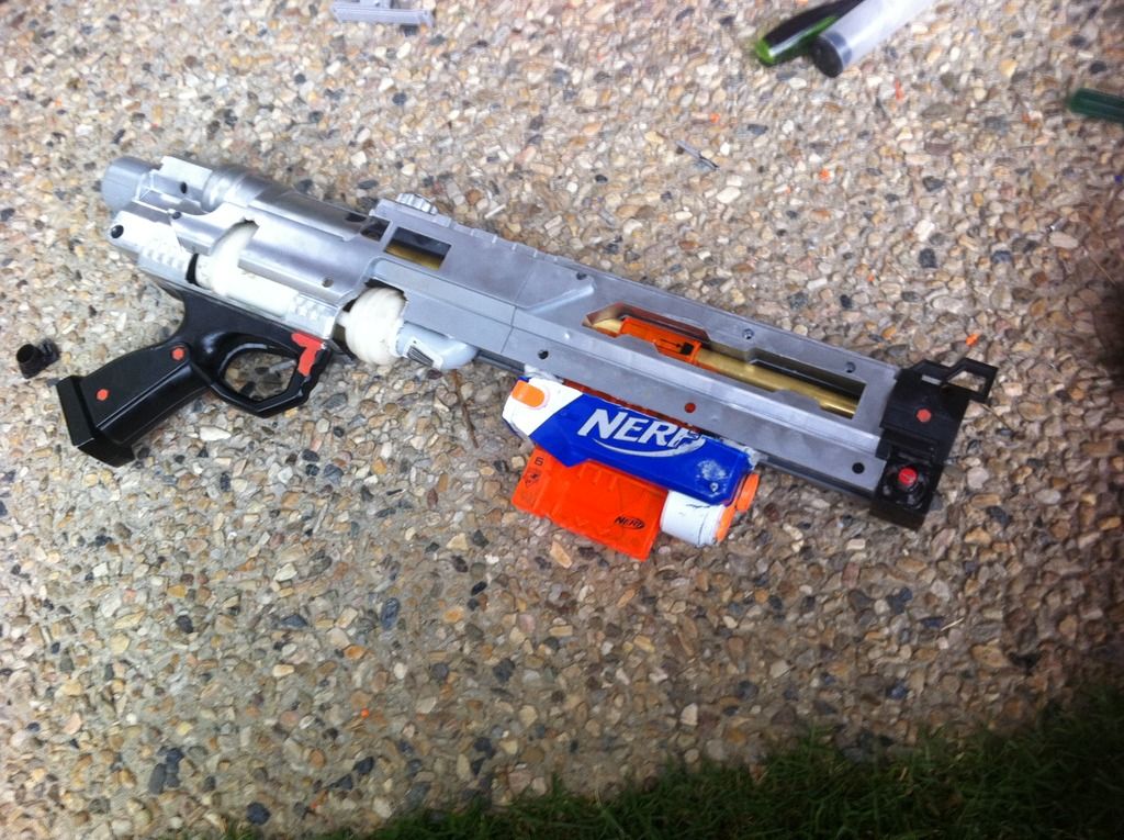
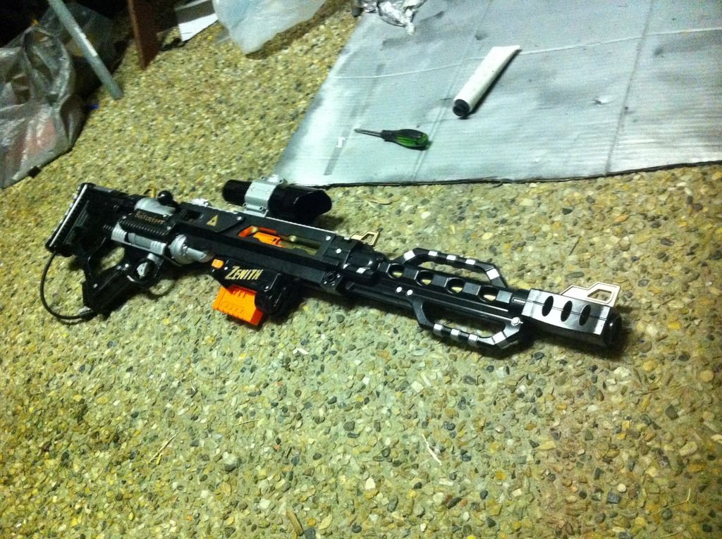
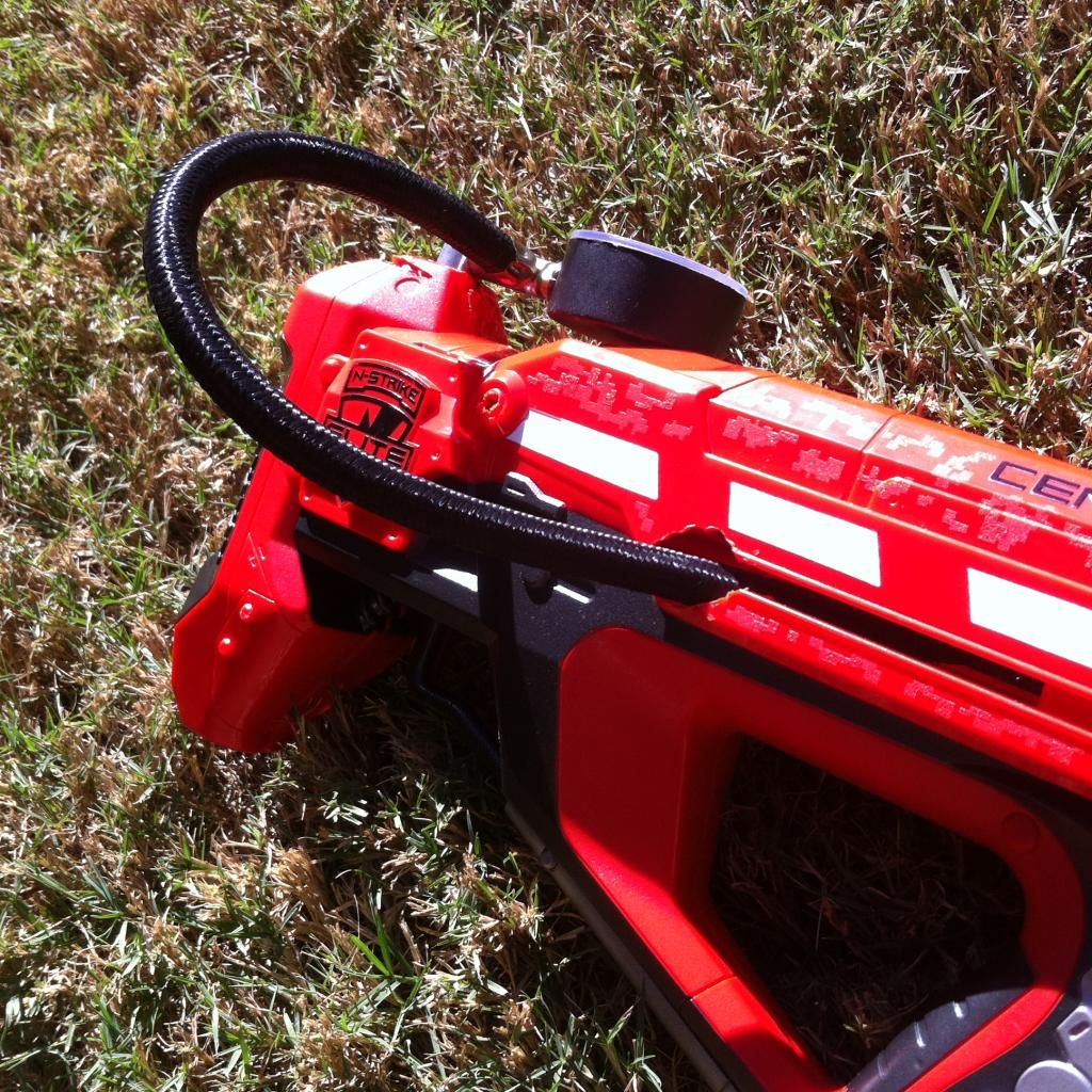
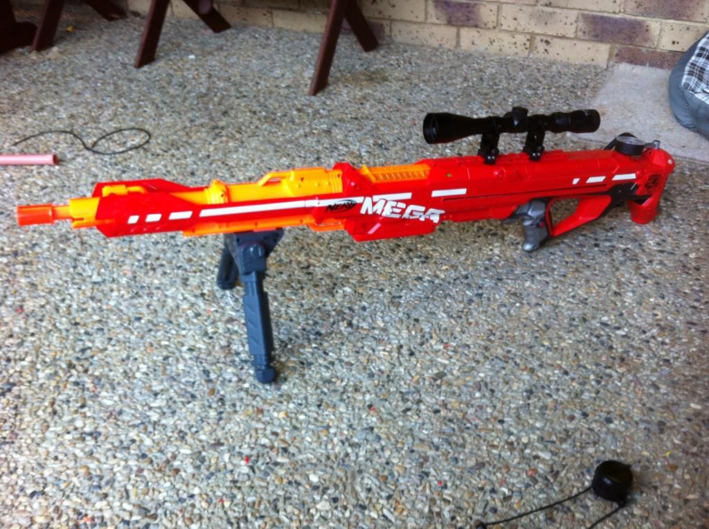
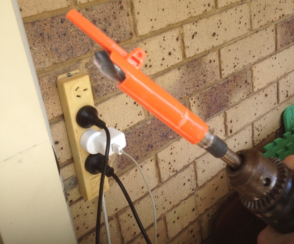
 
Money shot:
 
oz1.jpg
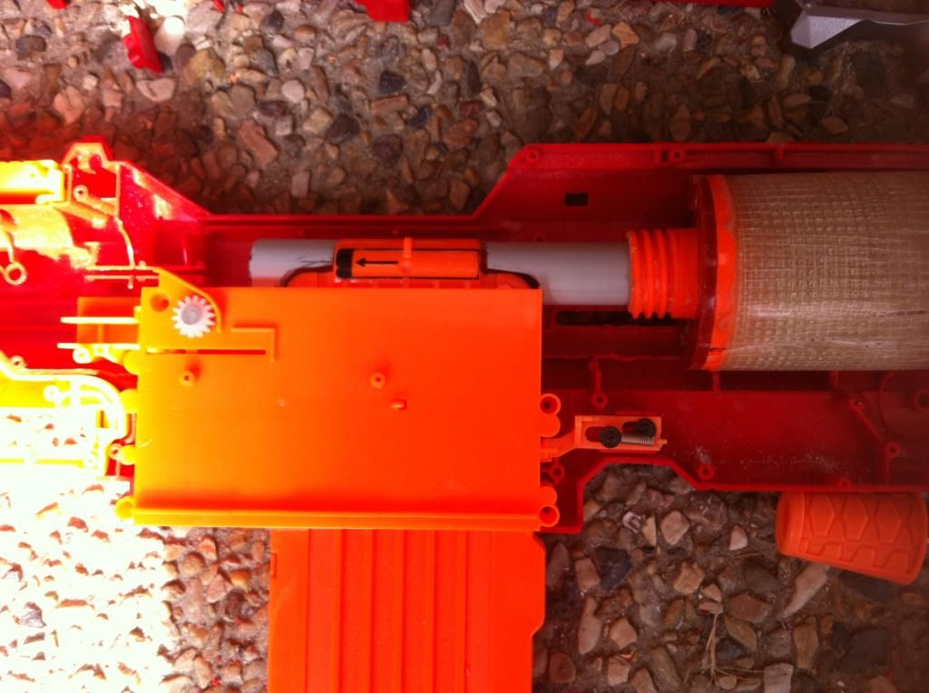
Finished pic of Sleeper breech inside the Longshot.
 
This warrants a writeup as it’s quite a deviation from the conventional Forsaken Angel brass breech and variants; this breech in itself has two main variants which will be covered at the points where the build process differs.
 
For this build I required an expensive drill bit; this has been since justified as I’ve built countless as commissions and the drill bit essentially paid for itself thrice over. If you’re able to find a cheaper alternative to the one I bought, I congratulate you, but warn you that it may not last too long, especially if it’s made from Chinesium.
 
You will need:
-1 foot length of 9/16” brass
-1 foot length of 17/32” brass
-a Longshot (duh)
-9/16” drill bit (mine is reduced shank and cost $40)
-3-day epoxy glue
-rotating pipe cutters
-Rotary tool and cutting wheel
-Good precision with said cutting wheel and a fair bit of patience.
 
The two designs are known as Conventional and Hybrid. For Conventional sleeper, you will need a hot glue gun and hot glue. For Hybrid Sleeper, you will need a Spenceworkz (or other) 3D printed Deadspace remover. I have yet to completely document the differences in performance, but that will come from my own testing as I am currently rebuilding a Hybrid Sleeper for myself, after building a few prior to this for commissions.


Here's what figures I do know from the year-and-a-half of various spring testing that the general community and I have done.

Turf Blaster Springs:

8kg - 180-200fps with full lengths, 200-210fps with half lengths.

10kg - 200-220fps with full lengths, 220-230fps with half lengths.

10kg + stock spring - 230-250fps with full lengths, 240-255fps with half lengths.

16kg - 220-240fps with full lengths, 240-260fps with half lengths


Hobby Mods 14kg spring - 180-200fps with full lengths, 190-220fps with half lengths.


Orange Mod Works springs:

8kg and 10kg - see Turf Blaster Springs values.
 
Let’s begin the meat and potatoes.
 
oz2.jpg
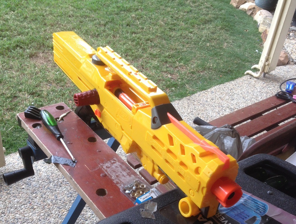
Starts stock, finishes looking stock. Let's do this.
 
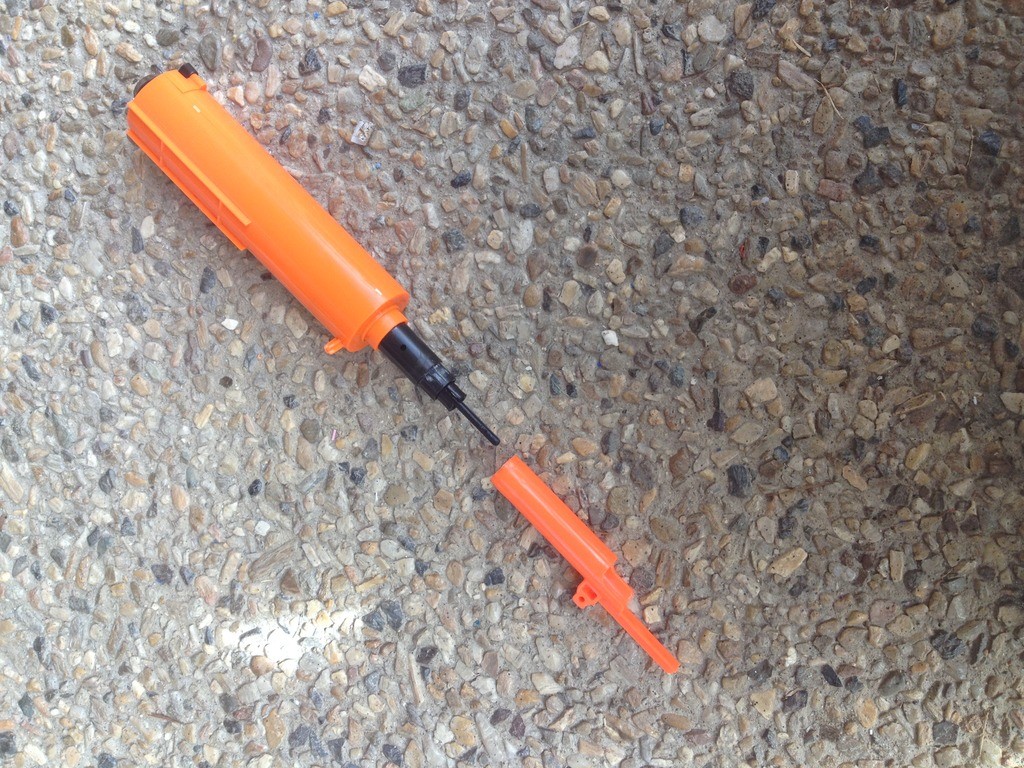
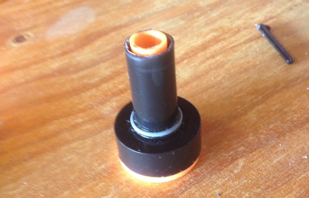
Begin by removing the boltsled assembly from your Longshot and knocking out the ever-annoying pin that holds the sled to the breech.
 
oz3.jpg
 
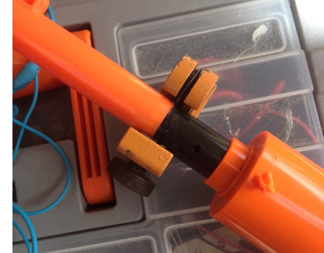
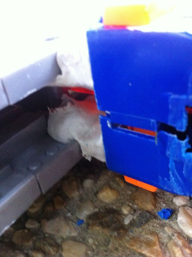
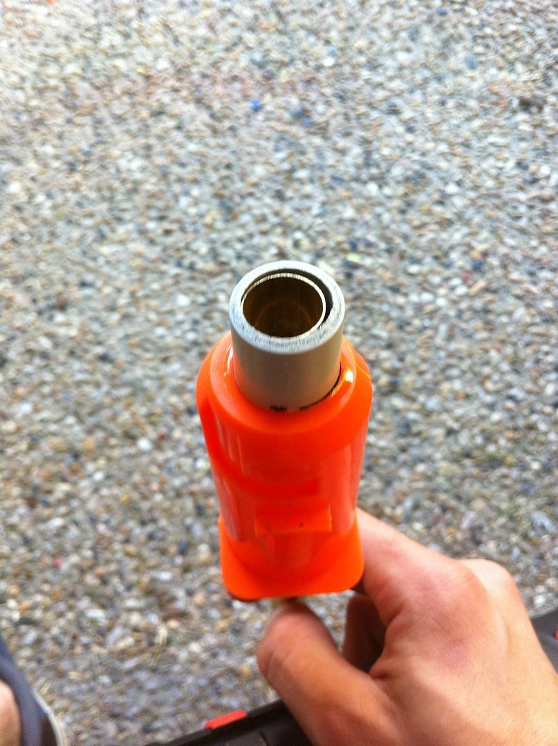
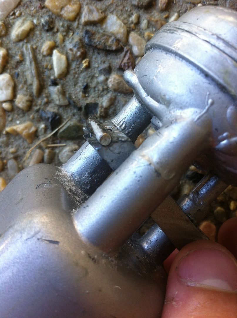
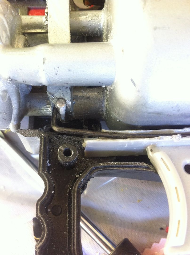
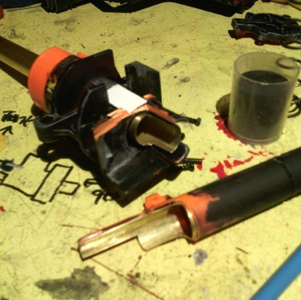
See the seam between the orange and the black? We’re gonna cut there with our rotating pipe cutters. Patience here. You need to be able to cut into it just enough to easily remove the orange piece from the black piece it’s glued to. If you’ve gone right through it and split it into two pieces, with the dart tooth still inside the orange piece, you went too far and this will make your life difficult. BE CAREFUL.
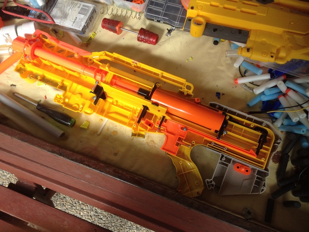
Once those two pieces are separated cleanly (if you fudged up as stated above, remove the black as much as possible from the orange piece by means of a grinding bit on your rotary tool), the most painstaking part begins: drilling.
 
oz4.jpg
 
This is the most painstaking part because there are two parts to do and the orange part takes FOREVER to do properly. If you rush, you melt your orange piece, your breech is unsalvageable. Got it? Good. Now, read carefully. DRILL. SLOWLY. IN. REVERSE. 
I didn’t stutter. REVERSE. Why? Because if you drill in forwards, you risk catching your drill bit inside the plastic, which will do one of two things: 1) tear it out of whatever you have it held in, or 2) grab and shred the plastic, and ruin the breech. Really, my method is counterintuitive but I’ve done this for several breeches now, so you can trust me on this.
 
oz5.jpg
 
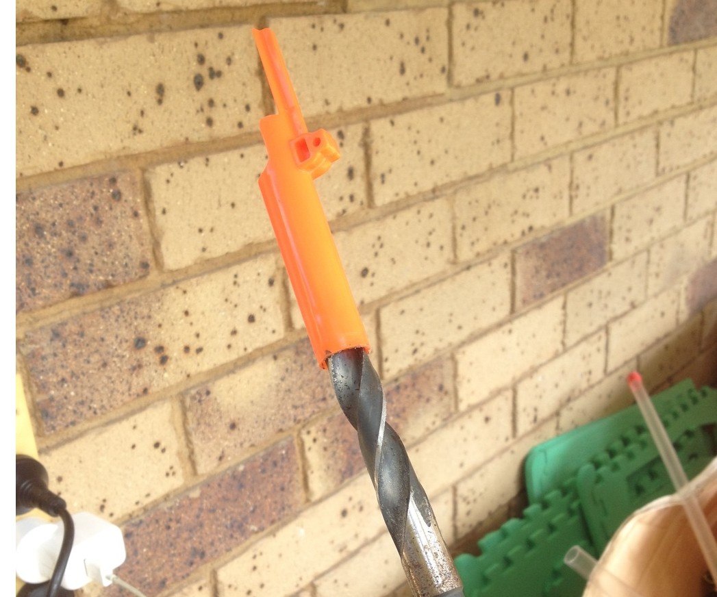
Whenever you’re ready to begin, get your 9/16” drill bit, fit it to your drill and begin. REVERSE. SLOWLY. Get it in as much as you can (giggity) while it’s still relatively cool, and then remove when it starts to feel warm (I drill in reverse with it in my hand; not best practice nor entirely safe but it allows me to gauge when it gets too hot quite easily). Again, too fast will melt your breech. 
Keep going, slowly, steady, til your drill bit begins to poke out the front of your breech. You’re good to go when it’s able to move fairly freely back and forth through the full length of the breech. However, you’re not done yet. Take the drill out and start fitting your 9/16” brass to it. Tight fit? Take the brass out, drill back in, wiggle around a bit. GENTLY. You’ve gotta ream out the breech until the brass almost effortlessly slides on. This allows it to just slide over the epoxy when it comes to gluing. Rinse and repeat fitting brass and drilling out until you can push your brass through your breech section fairly smoothly.
 
oz6.jpg
 
oz7.jpg
 
That’s the hardest part done, good job!
 
Next, there are two deviations on Sleeper breeches. This writeup will cover Hybrid Sleeper followed by Conventional Sleeper.
Hybrid Sleeper has the Hobby Mods Longshot Deluxe kit installed along with the brass breech section, so my design has compensated accordingly. It’s literally a matter of just shortening your brass enough for the deadspace remover to fit inside the back black piece, which I will refer to as the plunger cup. Remember to cut your plunger cup with a hacksaw to the right length, followed by installing the deadspace remover and epoxying it in place. Refer to THIS VIDEO for more information and skip to 3:33 to see more.


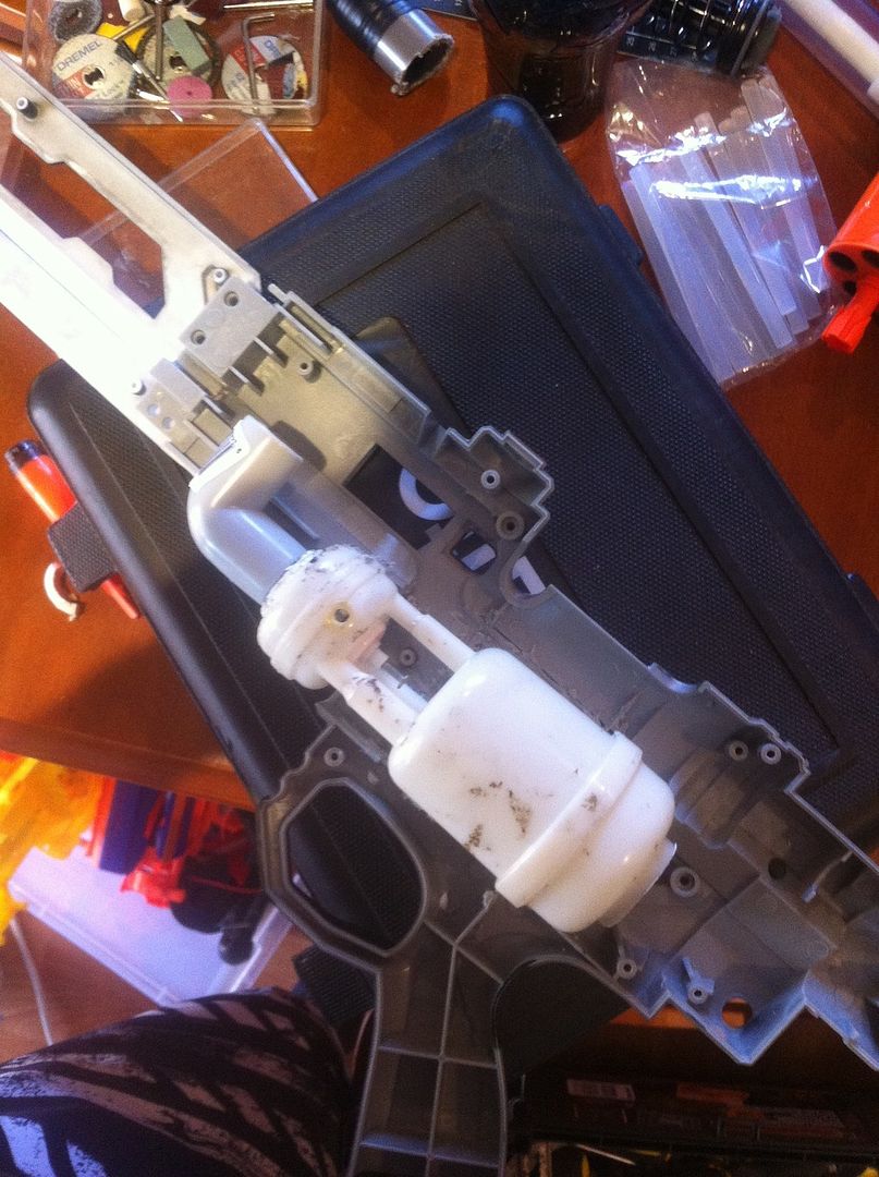
Since this product has since become redundant and is no longer actively used, it has been replaced with the deadspace removers available from Spenceworkz and other Facebook-based retailers of 3D printed Nerf parts. This part follows the same method as before, minus the hacksawing. Pictures of this section are old, and no longer relevant, but the principles remain the same. Any text with strikethrough font should be ignored, but are being kept as part of the original writeup.
 
oz8.jpg
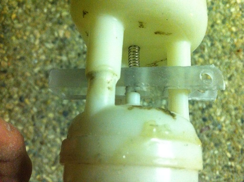
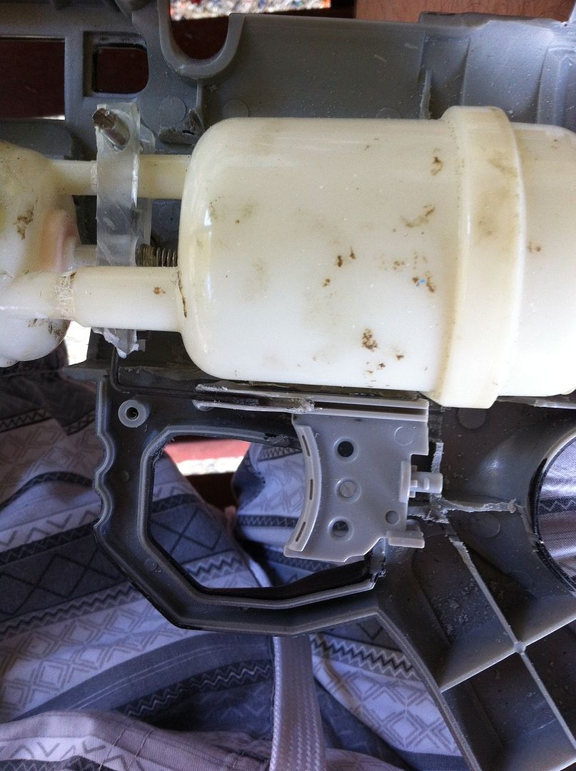
This cup has not been cut enough. Time to take it out and cut more! 
 
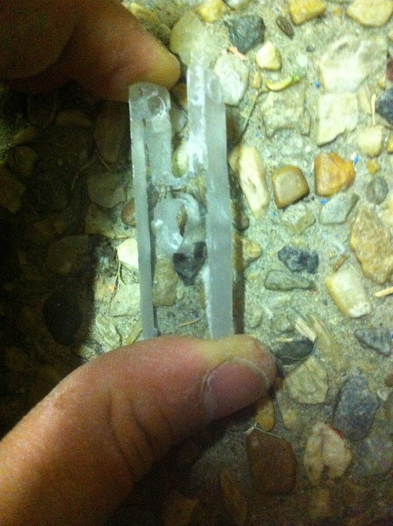
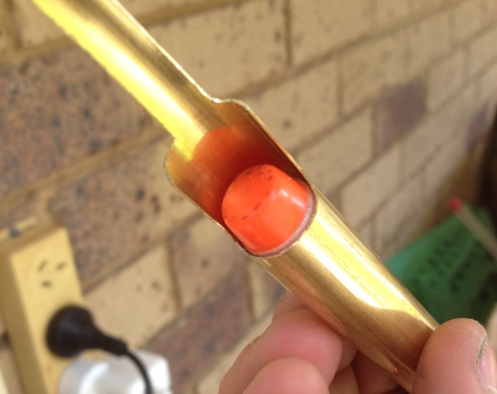
Also, you will want to trim your Deadspace remover at the brass end, until your dart's head pokes out without the foam...
Like this. I did it with the cut breech as it hadn't been epoxied in yet; it's doable with the stock plastic breech as well.
 
oz9.jpg
Once you have your deadspace remover epoxied in place, fit your 9/16” brass to the inside of the plunger cup so it’s right up against where the deadspace remover ends. Then fit your breech to the brass and mark where the breech tooth ends on the brass. Cut your brass to this length. Next, DO NOT REMOVE THE BREECH. Using your Dremel, cut away at the brass until it matches the shape of the stock breech. The more precisely you cut, the "sleepier" the breech. Once you've finished the breech shaping, remove the breech from the brass and sand the plunger cup end of the brass. Epoxy the brass into the plunger cup and allow it to cure. It is more structurally sound to add the epoxy to the inside of the plunger cup and to the outside of the brass as this seals it up and strengthens it from within as well as from outside.
 
oz10.jpg
 
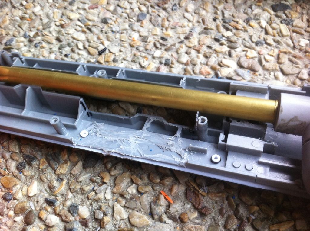
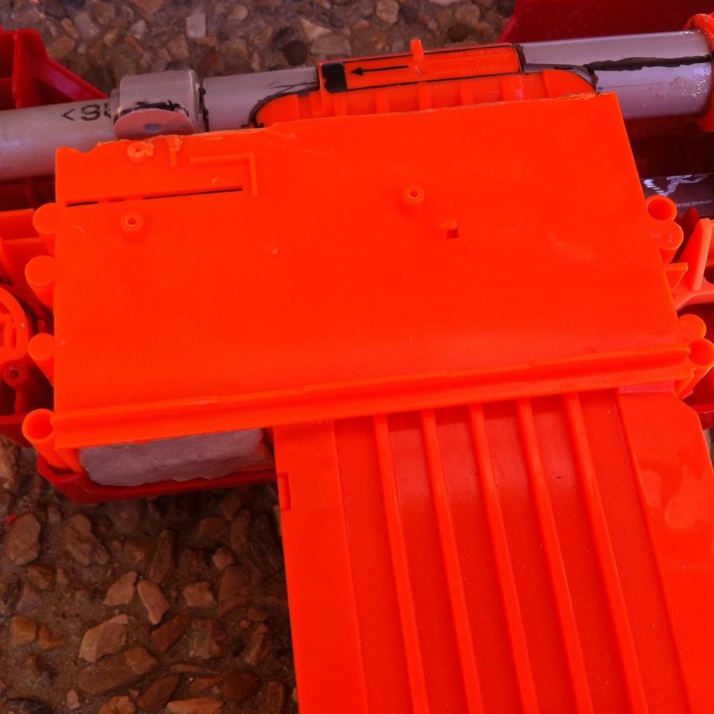
The Conventional Sleeper breech follows very much a similar method to Forsaken Angel’s design for deadspace removal; cut your 9/16” brass to the right length inside the plunger cup (the right length is determined by the length of your combined breech and plunger cup. This length is from the very tip of the breech to the back of the plunger cup). Once you have cut the length of 9/16” down to only what is necessary, make sure your breech is removed from your brass length and glue the back plunger cup to your length of brass. Epoxy, please. Once cured, fill in the dead space with hot glue.
 
oz11.jpg
 
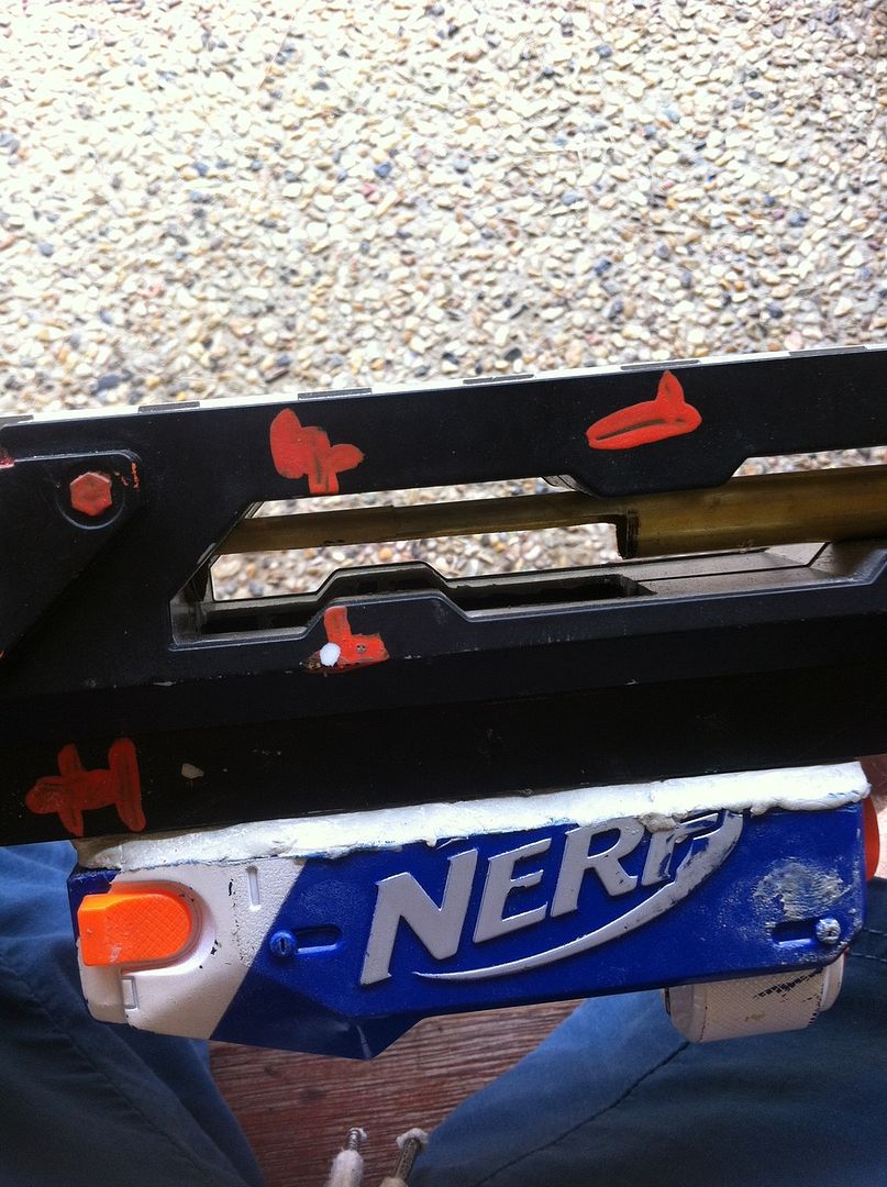
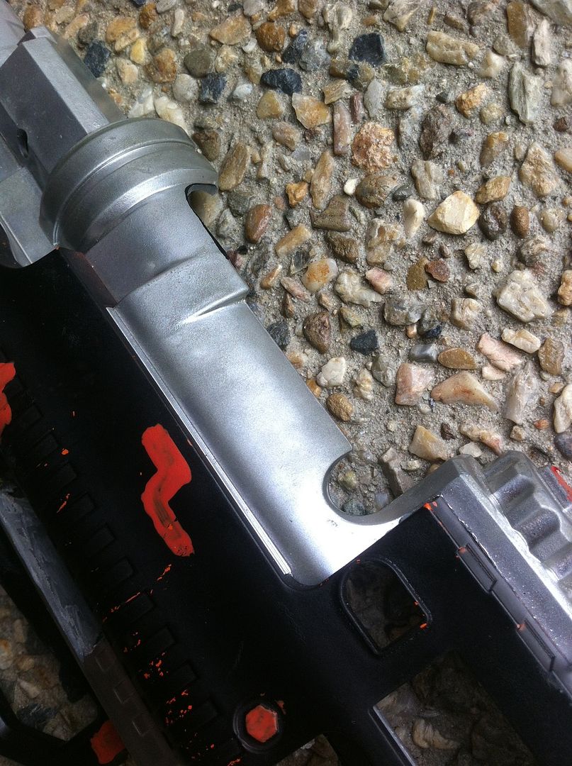
For either Sleeper breech, now that your brass has cured to your plunger cup, fit your breech to it and using your rotary tool with a cutting wheel, cut your brass to the shape of the stock breech as carefully as possible. The closer the match, the better, as it helps make it look clean and if you were going for “completely stock” like I originally was, then you gotta pretty much nail your cuts. Edges can be cleaned up with a grinding bit (or deburring tool), as can burrs and swarf, and I thoroughly recommend both, as the best possible finish also improves your seal. Once you’re satisfied with this finish, remove your breech again from your brass and sand it once over with around 120 grit sand paper. This gives your epoxy glue some serious surface area to bond to when you apply it.
 
Before proceeding any further, PUT YOUR BRASS BREECH SECTION AND PLUNGER CUP THROUGH THE PLUNGER TUBE HOLE. If you don’t do this, putting your breech back together will be nigh impossible unless you go lipless, and I’m not covering that in my guide.
Now, mix your epoxy again and apply it to the following areas: the halfpipe at the front of the plastic breech, and the outside of the brass all the way around. Slide your plastic breech onto your brass and clean up any excess you might have with a tissue. 
Wait for it to cure. While you do that, I thoroughly recommend making your barrel!
 
oz12.jpg
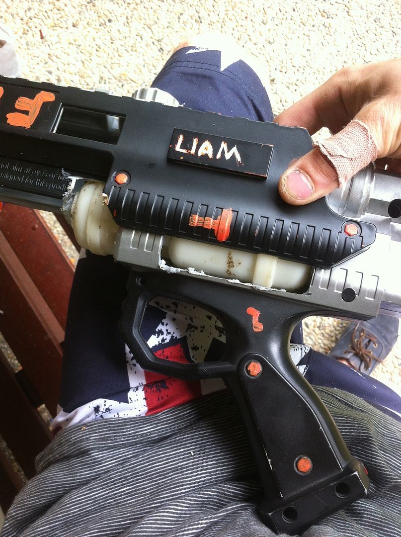
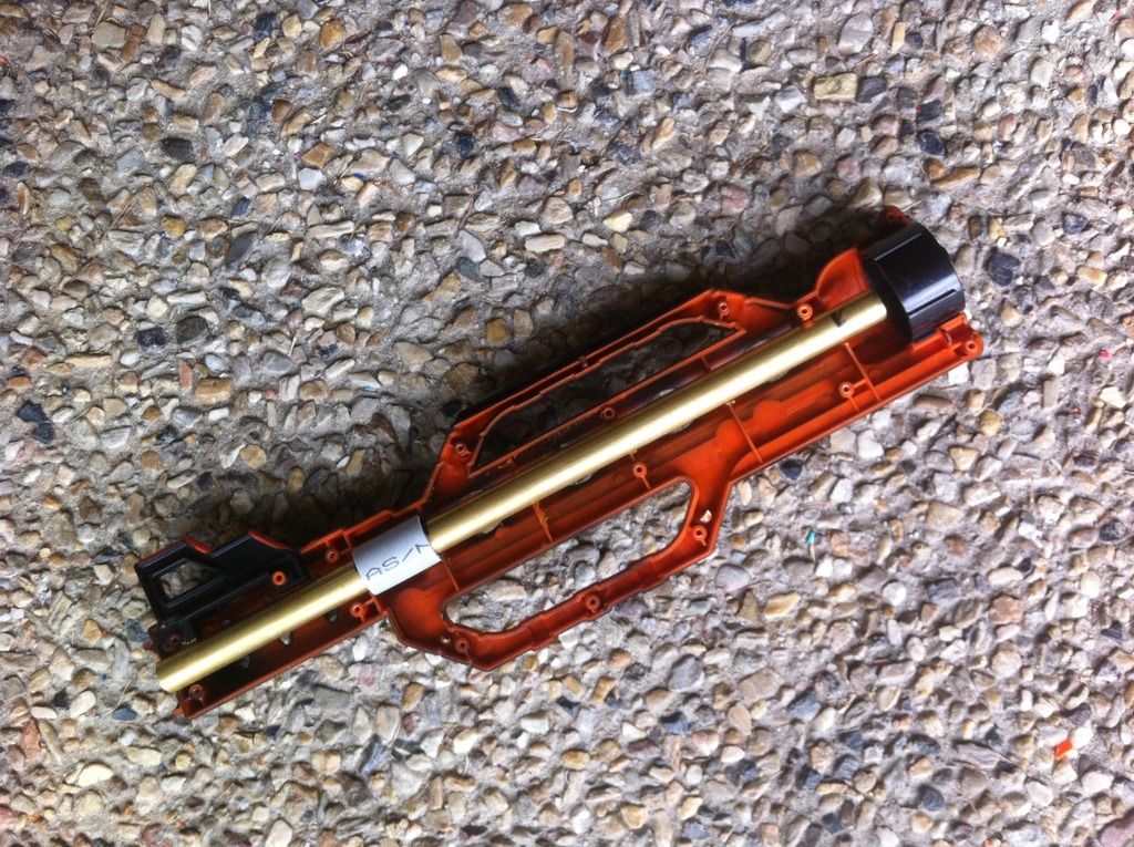
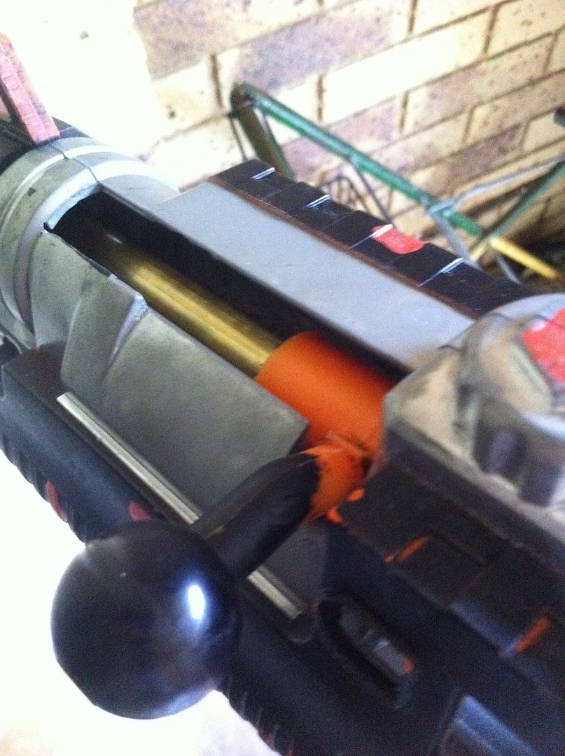
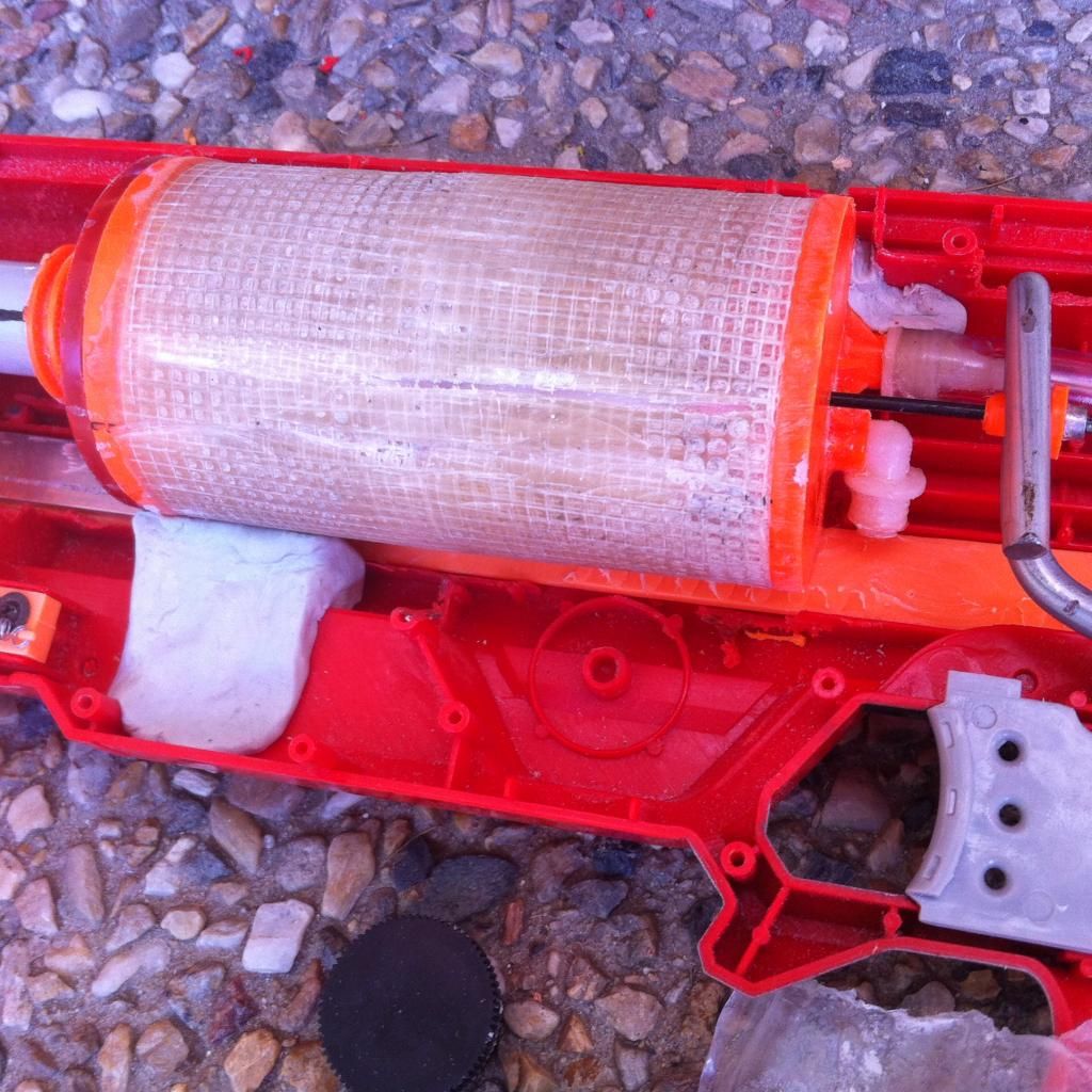
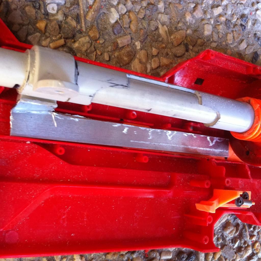
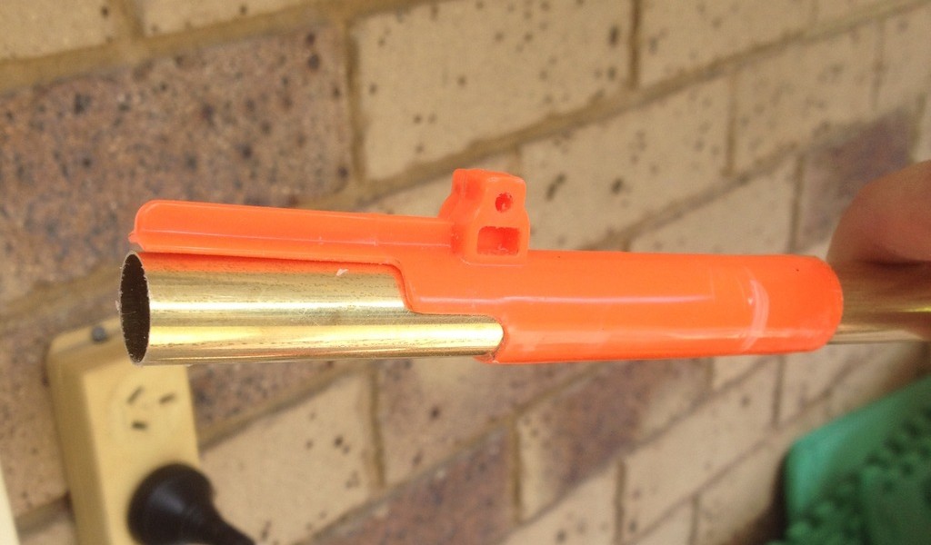
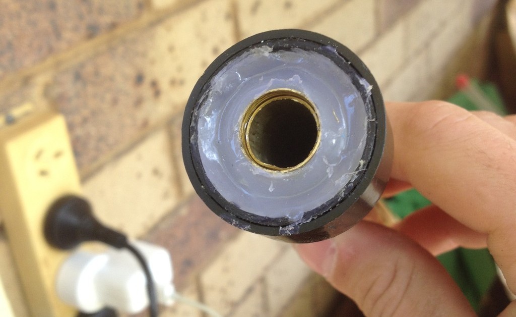
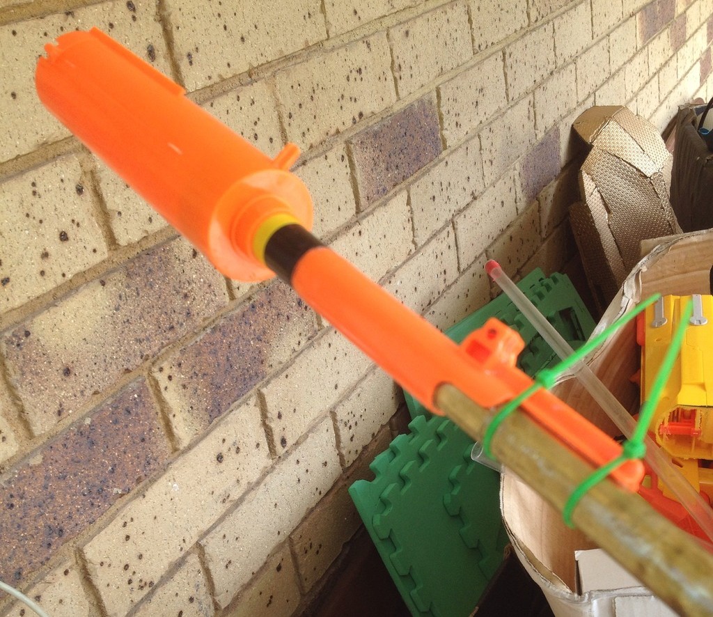
This picture is a bit blurry, I apologise, it's not mine; this is a pic taken by @frankenzilla_modds on Instagram who was replicating my design of Sleeper breech after I sent him one. Note the half pipe he has done in his breech. 
 
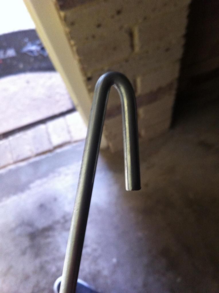
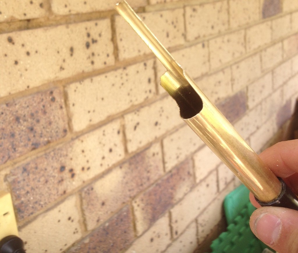
Get your faux barrel and your dart gate out, and grab your 17/32” brass. You’ll want to fit the 17/32” loosely inside both. Line up the end of your brass with the end of the dart gate, so the “teeth” and the whole tube are almost perfectly in line. Then mark out a half pipe using a permanent marker.  It should only be about 2 cm long, and no, before you ask, that doesn’t affect feeding at all by being shorter than Angel’s design; I have however attempted to do a breech without this halfpipe and the customer that received it has mentioned to me that his breech actually did have considerable feeding issues. So the halfpipe is a necessity. Cut it as smoothly as you can, round out the corners if you want. Then line it back up with your dart gate and hopefully it looks  centred properly. Wrap your brass in electrical tape at points inside your faux barrel, until your brass fits firmly inside your faux barrel; I don't need to photograph that as it's been done too often to need it. 
 
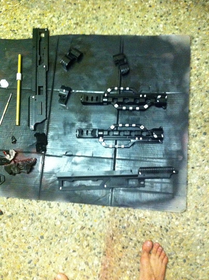
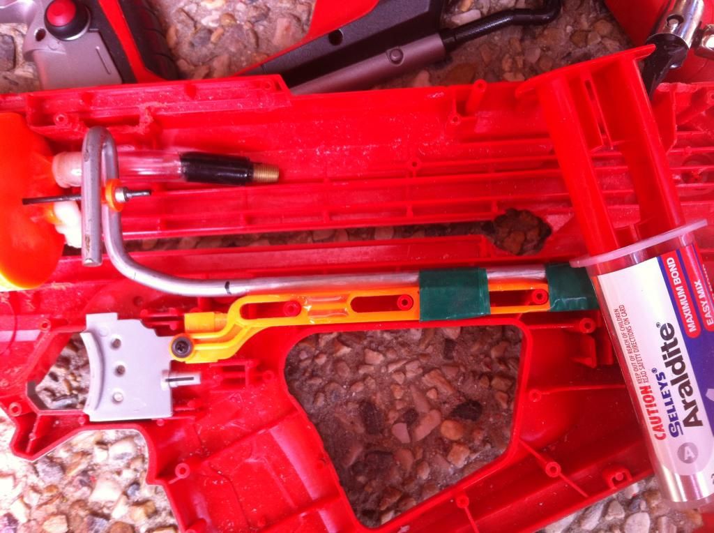
During curing time, I put my barrel inside my breech and cable tie it down, making sure no excess epoxy gets on the barrel; this allows the tooth on the breech to remain straight and centred during curing. 
 
oz13.jpg
 
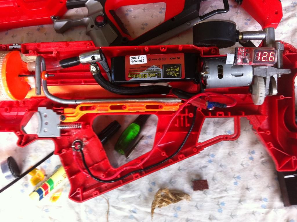
Once your epoxy has cured on your bolt/breech, you'll have your breech section ready to go. You'll need to assemble your plunger into your PT, and your bolt sled, once reinforced, back onto your breech. After that, you'll need to do your test fitting of the breech and make adjustment cuts as necessary to make sure your seals are ideal to the spec you want; believe it or not, some people need to do Longshots below a given velocity threshold, such as 220, which is the ideal maximum velocity at which FVJ darts are no longer able to consistently fly straight (This has been disproven as SCAR barrels make breeches with too-short barrels much more accurate). However, even below this velocity they can still have a tendency NOT to fly straight; however that's a digression I won't cover in this build.
 
That's really the gist of the build. There's more than one way to skin a cat with this build; you can epoxy the brass to the bolt section first and then epoxy it to the plunger cup after you're done, if doing a Hybrid Sleeper. This principle is also replicable in just about any magfed blaster, bar the Stampede for the reason that its stroke length when travelling is too short to seal the breech properly. If feeding half length darts, this is still possible.
 
I hope that covers everything people want to know. I'll post Chrony results of my Hybrid Sleeper of choice this weekend for comparison's sake to standard Longshot brass breeches of a similar kg rating. As it turns out, there's a lot more to account for than just spring force for a breech.
 
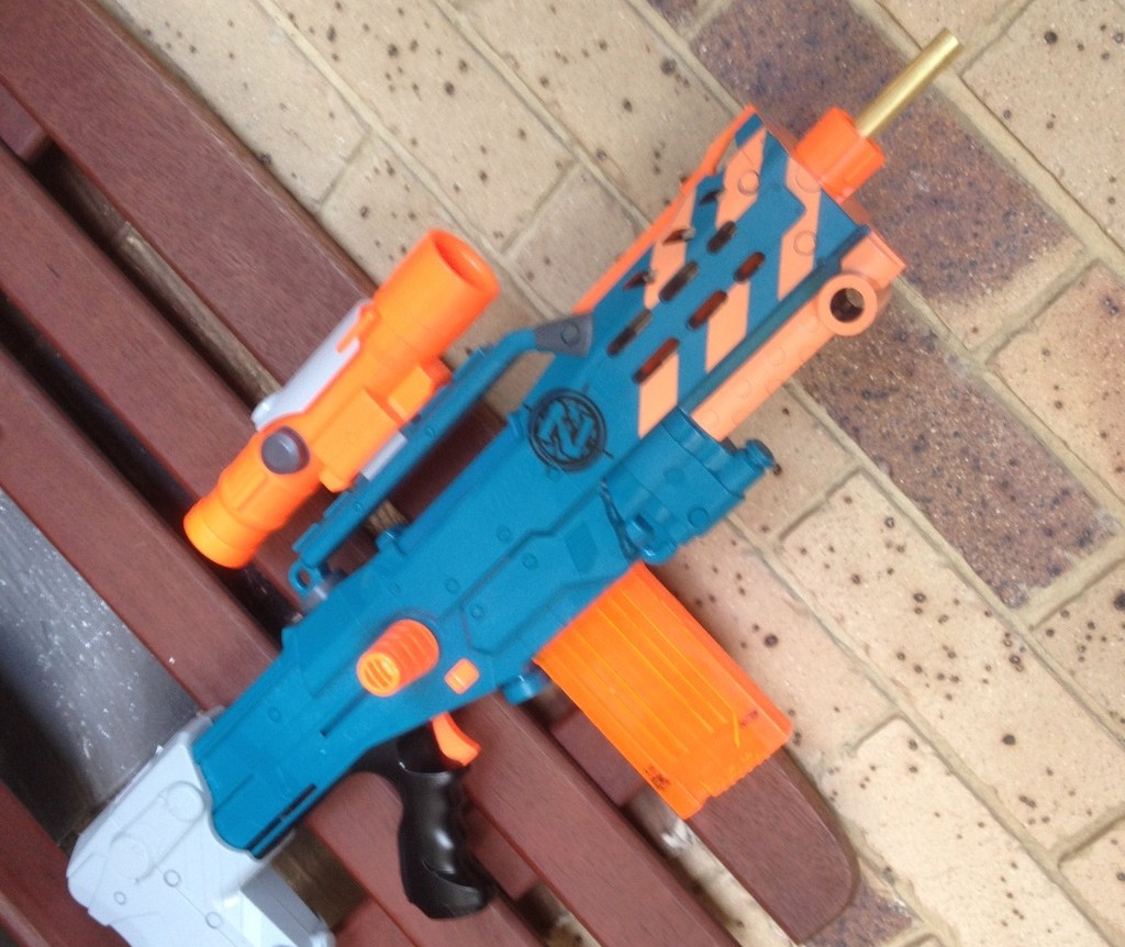
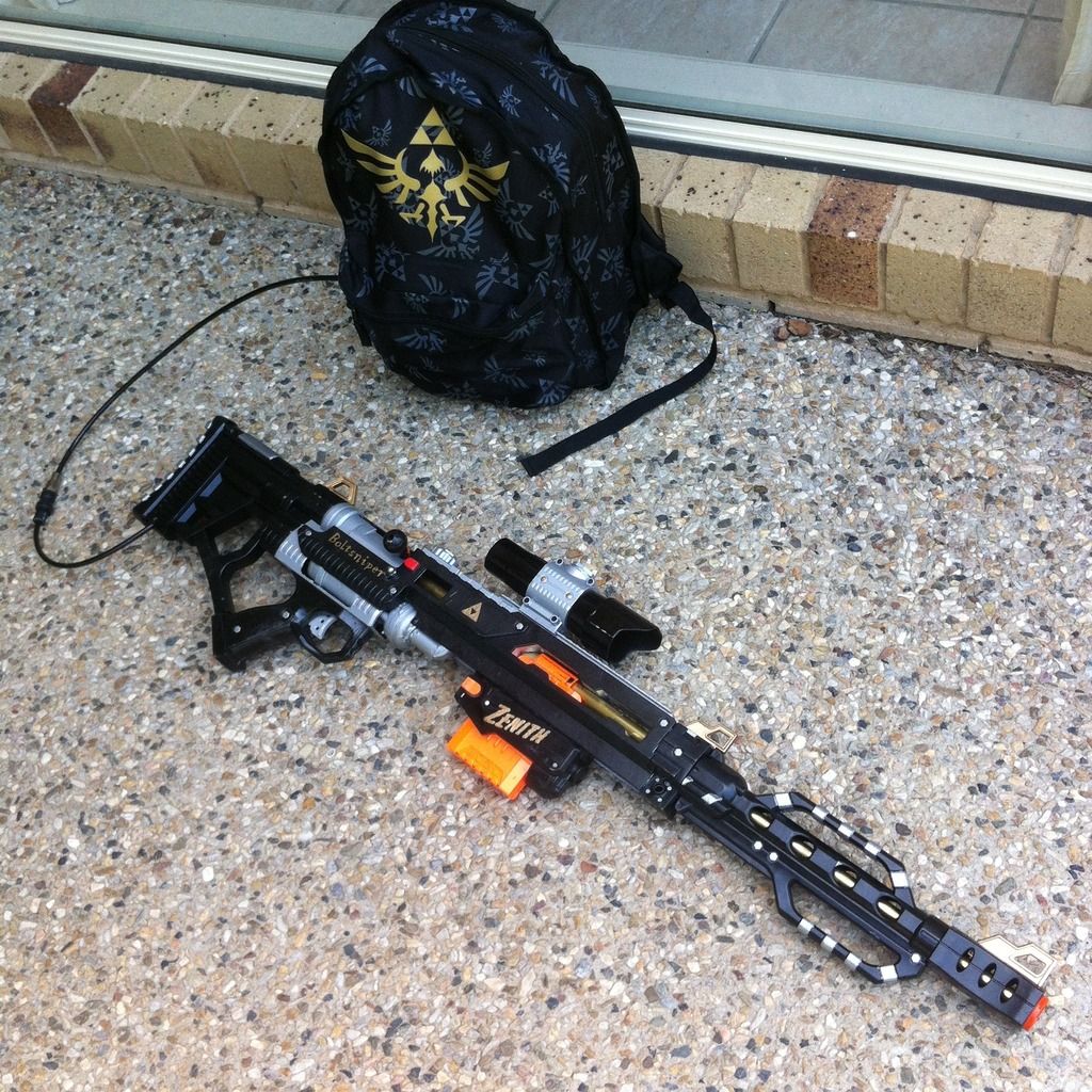
Bonus pic: ZSLS commission I did for a customer, who wanted a full foot of 17/32" brass barrel; I sheathed it in PETG for protection against the elements as well as to prevent core sampling people with the raw end of the brass.
 
oz14.jpg


Boltloser: the Blaster

19 April 2015 - 08:30 PM

I would like to start this write up by first disclaiming that this build is in no way affiliated with Boltsniper himself. I built this with the intention of making a bolt-action loser rifle, or bolt loser for short. The function of such is completed through the use of a backpack which I will include in a separate write up coming soon. This backpack is what makes the blaster's bolt action most effective and almost completely "true bolt action".

First, the money shot:

Posted Image

Now, what I required for the blaster itself:

-Max Force Shadowhawk (the blaster shell)

-4B tank, with or without a lever trigger (I'll go through optimizing it in the build, how I have done it is due to how I received the tank second hand, if you choose to replicate this, I will show where to put the hole for the air line.)

-Multiple lengths of 17/32" brass, 9/16" brass and 19/32" brass

-Epoxy putty, super glue and epoxy glue

-Any Nerf magwell of your choice (I used a Retaliator magwell in the absence of a spare Stryfe magwell, which would've made it more streamline and less blocky)

-20mm conduit tee and 90° bend piece

-20mm conduit (1/2" PVC for 'Mericans), approximately 30cm so you have spare bits to use.

-Air line

-Check valve for air line

-connector for your air supply

-Your choice of trigger (I used the Ret trigger after sacrificing the Ret magwell)

-Really tough wire of any diameter

-Small metal bar of any length but particularly thin diameter (the pins from N-strike boltsleds are particularly useful)

Alllll right, I think that's everything.

Let's begin.

First, gut your MFSH shell. Keep your bolt piece, your pump handle (optional) and all shell parts, except the pump rail. That shit is useless, as are most of the other parts.

Now, begin grinding out the shell ribbing around your trigger grip area, especially just above it. I put my 4B tank in (after completely removing the pump end) and left a base for it to lie on, and just ground out all ribbing that impeded the shell closing over the tank.

Posted Image
Posted Image

Once you have your shell able to close over your tank, you have multiple choices of what to do next. You can either do the air line to your choice of air supply (which for me is my "Zenith" backpack), followed by the lever trigger assembly, or you can do the breech and bolt action sections. I will go over the breech and bolt action sections first.

Okay, this section is a LOT of brass work and your tool of choice here will be a Dremel/rotary tool. Let's work on the brass muzzle first. This part I worked on to make detachable for transport purposes. It's wickedly simple to make.

First, take apart your barrel attachment, and take out the section of tubing that the blaster uses for its pitiful spitballs. Close the attachment again, and get either a 17/32" drill bit (not quite easy to find) or your rotary tool's grinding bit and widen the pipe guide's ribbing JUST enough to accommodate your first whole foot length of 17/32" brass. Insert, line up with the front of the muzzle so it is as flush as possible, and mark where the original pipe's "holding piece" sat, on your brass. Cut a length of 20mm conduit at that length, and fit it to your brass, epoxying it to the brass.

Do NOT allow it to become epoxied to the inside of the barrel just in case you feel like taking it apart later, which I haven't had to yet, but just in the instance that you actually do need to take it apart, better safe than sorry.

Posted Image

When it is finished curing, put the whole barrel extension back together. Do NOT fret about the back part protruding from the extension, that will come in handy soon.

Let's start on the connection to that piece first. You will have to do the magwell section now too, so flex your shell integrating muscles and get to work. Here are some pics of my Ret magwell integrated from inside and outside. I do plan to go back and clean up the shell holes in front of and behind the magwell later on, but haven't got around to it at this stage.

Posted Image
Posted Image

In order to do this really effectively, you will have to first grind or drill out the pipe holes to accommodate your brass lengths up the top here. I lined the back of my clip up with the front of the opening on either side of the shell. The ribbing in the underside and inside WILL need to get ground out or cut off to accommodate a clip feeding from underneath. Start by grinding out the brass holes, sleeve some 9/16" and 17/32" to the muzzle brass, and run your brass right back to behind the clip.

After you have decided where to seat your clip, throw up your magwell section with clip inside and line it up with your shell as you see fit. If it doesn't fit, grind more shell ribbing until the clip can wrap around the brass.

Posted Image
Posted Image

Once it sits nicely with the brass between the clip lips, get to work making the magwell sit still. Putty is your friend, be liberal and grind/sand away at anything you don't like/want, after testing that your clip still feeds into the brass.

Now you have that section done, feel free to clean it up, however you see fit.

Here's a quick tip for ya: if you like a faster release magwell, use a Stryfe magwell. It's also more streamlined than the Ret magwell.

Time to go to work on the breech.

This is probably the hardest section of the overhaul, as the brass work is long, complicated, and took me a LOT of waiting, lubrication, and trial and error to get the breech and bolt action to function as smoothly as it does.

This part has a small section of preparatory work with the tank: prep some epoxy glue, and get your 90° bend connected one end to tank, one end to the bottom of the tee (You can leave the tee friction-fitted for now, epoxy it in later). Get your inline tee sections lined up with the brass you set up before. This may involve cutting your tee end and bend ends so that you can connect them as flush as possible.

Posted Image

Cut some 20mm conduit to join them properly. Next, cut 2 lengths of 2cm from your conduit and fit them into the inline section of your tee. You will now need to cut matching lengths of 19/32" brass and epoxy them into place in the 20mm conduit. I'll explain their function when we get working on the bolt action. You may want to have a "sacrificial" piece of 9/16" brass, VERY well lubricated, to sit between these two lengths of 19/32" to make sure they're perfectly aligned. This part was one of the most frustrating for me, and please don't hate me if it doesn't work first time. It didn't for me either.

Once you have that working, your tee will look like this:

Posted Image
Posted Image

Alright, NOW we can get to work on the breech. Let's start by connecting the barrel extension to the breech portion of brass. Cut a 2cm length of 20mm conduit and grind out your barrel extension connector piece to accommodate 9/16" brass. Now cut about 5cm of 9/16" brass. Sleeve it over the back end of the barrel extension (which should've been 17/32" brass if you were listening) and sleeve the conduit over that. Do NOT glue anything yet. Now, connect your barrel extension connector to the barrel extension, while still separate to the blaster shell itself.

Posted Image

Feel free to NOW throw some superglue down inside the connector, to hold the 9/16" piece tight to the extension connector. We will make this more solid a little later. Sleeve some more 17/32" brass into the inside of the 9/16" in the back of the connector. Push it through until it contacts the extension's brass. Superglue the seam that the 9/16" makes with the 17/32". Now disconnect the barrel extension from the connector, and insert the connector gently into the blaster. If you've done it right, at this point your 17/32" brass will just sleeve beautifully through your clip lips. Close the shell. Grab that conduit section you cut for the extension before, and epoxy it to the front of your blaster over the top of your 9/16" brass connector piece. It will look like so:

Posted Image

If you want to make this connector piece even more solid, put some 20mm conduit on the inside of the connector and epoxy it to the brass as well.

Use needle nose pliers to widen the lip of the 9/16" brass a little, to make connecting to the extension a little more fluent and painless.

Now, if you've worked with Longshot brass breeches before, you will know what to do next.

CLIP HALFPIPE!

Posted Image

Or quarterpipe. Either will work, as neither of the two pieces comprising the brass breech are actually load-bearing at all on the breech end, and will not bend if you treat your brass and your blaster properly.

So get to work on your 17/32" piece. There are some really intricate brass parts coming up, so consider this your warmup.


Now this part is important to note: the brass piece you are using for the half pipe MUST end where the back of the clip is. Well, sorta. For my design, certainly helps for minimal brass cutting and for optimal breech seal.

Next, we will prep the shell for accommodating a full-draw breech, because in its stock form, the bolt action is too short to accommodate full length darts. If you want to make it Stefans-only, sure, don't cut the bolt guide, but otherwise, I find that cutting back to the next rise in the shell is the best way to accommodate full length darts in the breech draw.

Posted Image

Right, you are gonna need to take very careful notes on the bolt assembly here. My design uses the tee section as the air flow section (duh), with TWO sizes of brass inside it to make the breech loading super-smooth, as well as eliminating dead space behind the tee.

First, get a full foot length of 9/16" brass. Where the breech section is, close it over the 17/32" brass and make your halfpipe/quarterpipe to the length you deem fit. Seal the breech after cutting your half/quarter pipe. That will sit inside the tee, and protrude from the other end. This is good.

Mark on the pipe where the tee shrouds over it. This will come in handy soon. (I forgot to take a picture of this section, I apologise if it is unclear.)

Now, sleeve a full foot length of 17/32" brass inside that, and position it further back inside the shell so that the back ribbing behind the bolt section accommodates it. This piece of brass is our "bolt guide", which will sit perfectly stationary while the bolt slides back and forth, and will streamline your bolt travel to be perfectly linear. Make sure your 17/32" brass sits nicely within the ribbing, grinding it slightly wider if you need to, and apply a small amount of epoxy putty to the brass on either side of the ribbing. Close the shell to ensure that the putty will mould to accommodate the ribbing. Once the putty has cured, you will be almost finished with this piece. We will deal with the final preparation for this piece in the next section.

Posted Image

The bolt from the MFSH can now be fitted to your 9/16" brass if you want. If you have cut your breech and marked your (closed breech) tee-concealed section, you're able to take it apart from the breech and tee, as well as the bolt guide. Use some scrap plastic or putty to fit the bolt (which has a slightly-too-large ID for the brass) in the upward position to the back of the brass, while the breech rests, halfpipes aligned.

Posted Image
Posted Image

This makes your bolt travel properly as the breech remains in line back and forth along the bolt guide.

Now, for the reason you marked out the concealed section of the brass while the breech is closed and the bolt is forward. Remove the breech/bolt piece from your shell/tee. Assuming your pen markings are still visible, roll the piece over so the half pipe is now the bottom half and the bolt is upside down. Draw a line between the two markings and find the centre point.

I forgot to photograph this section exactly as I'm about to describe it, so pay attention.

We need to cut an "air flow" hole on the underside of the breech. Basically, as the breech is closed, the 19/32" pieces you cut before are sleeved over the tee section, sealing the brass and blocking air escape. By creating an air flow hole in the 9/16" brass, you allow air to leave only through the hole, which is what allows you to direct all your energy into the breech and fire the dart.

Cut a square hole on the now exposed underside of the 9/16" brass. Make sure there is at least 2cm of uncut brass on either side, allowing you to maintain your sealed sections inside the tee.

Posted Image
Posted Image

When that is done, mark your 17/32" bolt guide in a similar manner when inside the shell. Cut another air flow hole inside it. However, this part is different. In the back part of the bolt guide, we are going to stuff a blob of putty inside it, to block off the hole and the dead space that it would create. Wait for that to cure, then slather it in epoxy glue and allow it to cure to be completely sure of no leaks.

Posted Image

One more thing: after your bolt has cured to your 9/16" brass, lift it into the open position on the bolt guide and note which part of the bolt sits closest to the 4B tank. You may need to grind away a flat surface on this portion of the bolt to prevent it colliding with the 4B tank while traveling backward and forward.

Once that is all finished, you will have a bolt assembly that resembles this: (my tee wasn't epoxied in at this point):

Posted Image

Now, you pretty much have a completed bolt action breech that feeds clips.

Time to link it to an air supply. Then we will do the trigger, and we are done!

Now, here is my connection for the air tank to the air line. I received the tank with the hole like this and decided it was easier to just make do with the hole as opposed to trying to seal it and relocating a hole to where I choose to put it. I may actually seal it up properly later on and relocate a new hole to the back for the purpose of making the blaster easier to reassemble.

Posted Image

First, seal the check valve end of your tank. I did this by throwing putty inside the valve gap, then sealing it over with mesh tape and epoxy glue (does anyone see a pattern with my airblaster builds?).

Posted Image

Next, pick a place around the back of the tank and drill a hole for the air line to go into. I use 6mm air line, so I recommend a 6mm hole. Throw the line into the tank and seal it with liberal amounts of epoxy.

I drilled a hole in the stock connection nub, the stock connection port on the stock and a hole under the bottom of the stock to feed the air line through. I also put in a check valve to allow the blaster to remain full of air after my supply line is disconnected from the blaster, which allows me one extra shot before needing to reconnect.

All that is needed after that is to throw your air supply connection piece on the end of that air line, however you see fit (if you are using a HPA connection it will be different to my connection piece).

That gives you a complete air supply for your blaster.

Now for the trigger.

For anyone that will use a 4B tank with a lever trigger already on it, I envy you. Both 4B's for the blasters I have built with them didn't come with lever triggers. I was forced to make my own.

So here this part goes.

I had some 8mm polycarbonate sheet that I bought ages back, it was $30 for a 40cm by 40cm sheet. Australian products limit my availability ridiculously for things like this, but I have more than got my money's worth out of using it for projects such as this. There was no thinner option at the time, however I have gone back to Bunnings since and found thinner acrylic and PVC sheets.

I started by simply measuring the gap under the two pipes that connect the 4B tanks. Then I measured the width of the top pipe and cut a sliver of polycarb just wider than the top pipe, and just thinner than the bottom two pipes. I also drilled two holes to allow the lever to sit comfortably over the firing pin. The result was something that resembled this:

Posted Image

The top two arms sat above the 4B in the shell but below the bolt section. I then ran a length of threaded rod through two holes I drilled in the shell to use as a pivot point.

Posted Image

Also, I installed a return spring behind my firing pin, as the tank's stock pin was a bit sluggish to return. It's superglued on, so with a little persuasion I can remove it if I need/want.

Posted Image

The bottom of the polycarb got a small niche drilled sideways into it, after investigating and realising that the polycarb could NOT withstand firing pressures above 50psi.

A metal bar was epoxied to the bottom part here.

Posted Image

The trigger itself was the Retaliator trigger, cut down and fitted as comfortably to the shell as possible. A hole had to be cut into the inside of the trigger grip to accommodate the Ret trigger.

To connect the Ret trigger to the lever trigger, I bent a piece of BBUMB lever trigger wire I had, which can be substituted for music wire/coat hanger wire for the sake of strength. It got epoxied into place near the back for strength. After fitting, testing and refitting to make sure it was all structurally sound, this was the last part of the blaster to complete, and I got to painting.

Posted Image
Posted Image

Paint pictures:
Posted Image
Posted Image
Posted Image

And the finished product again:
Posted Image

Firing demonstration coming soon.

I hope this write up was easy to follow, and if you have decided that you want to make one, feel free to fire any questions at me about it.

The TitanTurion

13 April 2015 - 06:54 PM

First post here, let's make it a good one.

This design was originally done by Apollo441 in Melbourne, Australia, but a writeup was never done. Hence, I feel since my design is considerably different to his (and more space-effective), I can call dibs on the writeup.

Long and short of it: The Titanturion was built to be a micro-firing, clip feeding, compressor powered Titan, and it uses the real estate of the Centurion shell to fit all the components.

Let's begin. First, I gutted the Centurion.
Posted Image

Note where I have ground out the shell. This is where I fitted my Titan tank.

I then reinforced my Titan tank as per MiG's writeup with fibreglass mesh tape and epoxy glue, and fitted some garden air tubing to the inlet valve, as well as epoxying a Schrader valve to the end to make the tank sealed. This valve makes it easy to connect any pump/compressor of choice as most pumps are designed to connect to these valves.

Posted Image
Posted Image

I also grabbed a rather large tent peg (6mm diameter) and bent the end of it into a more uniform U shape, which will be a means of direct trigger a little later on.

Posted Image

Time to fit tank to shell. This part was a lot of grind-fit-close, test to see if shell fully closes, rinse and repeat until shell fully closes over it.

This was my final result (taken a little later on in the build, but remaining relevant for now):

Posted Image

Note the putty in the corner and underneath; these are there for the sake of keeping the tank in place.

Next, I did the trigger. I bent the tent peg to a roughly 90 degree angle and taped it to the Centurion's trigger rail while I applied liberal amounts of epoxy glue.

Posted Image

This was a two-stage epoxy process; I applied epoxy to one side, allowed it to cure and then flipped the trigger assembly over and epoxied the other side. This gives it enough strength to withstand being pulled vigorously at pressures above OPV levels. Also note the hole in the bolt rail here; this is to accommodate the air line from the compressor. Now we will move on to that.

Integrating the compressor was a similar task to the Titan tank; grind, fit, test shell closed. The difference was, the pressure gauge and air line had to remain external, so I ground out a hole at the top of the shell on both halves to accommodate the compressor as cleanly as possible. This is the result after running the air line back through to the Titan's Schrader valve:

Posted Image

We'll move onto the breech next. This is a three-part process: One is making the conversion to streamlines and making the receiver section, two is making the barrel, three is filling in the magwell to make sure Nerf streamline clips fit snugly and without wobble.

1/2" PVC (20mm conduit in Australia) came in handy to make the clip receiver section. Basically I just threw a clip on it from through the magwell, drew around it, cut it out with a Dremel.

Posted Image

The barrel was made by simply fitting some PVC/conduit fittings to a (insert your choice of barrel length here, I used 65cm) length of 1/2" CPVC (16mm conduit in Australia). I used a piece of 20mm conduit, with a 20mm conduit mounting saddle to link it to my bolt rail, which was the stock bolt rail, with a length of 2mm sheet aluminium epoxied to the end, cut in an L shape and bent to connect to the mounting saddle.

Posted Image

Behind the tank, I drilled a hole in the bolt rail and fitted the stock bolt to the side to give me priming ability. Do note that the loading of this blaster is forward-back, as opposed to back-forward, because of the Titan tank. (I am left handed; the right hand side of the shell is most convenient for me to prime using the bolt. You can do this with the left hand side of the shell if you so wish.) It's secured on the inside using a blob of epoxy putty. I don't have any photos of this until after I wired up the compressor; I did that a little later.

Now, after testing this a few times, I was having trouble getting the bolt all the way forward due to shell ribbing. Pretty much grind out the inside of the shell just in front of the magwell on both sides and you'll be fine.

Next is filling the magwell. I used liberal amounts of putty in front of the clip after thoroughly lubricating the test clip. Then to do the sides of the magwell, just do the same thing with less putty, and grind away at the putty if you have difficulty loading the clip. It's a LOT of guess and check. If you do it the way I did, your clip will be held in by the Mega clip's clip lock and won't wobble on either side after you've ground away enough excess putty to successfully load the clip. Pic below of a midway-through-putty magwell.

Posted Image

Now, we will wire up the compressor. Simple diagram, if you have done a Stryfe you can do this. I initially used 15A rated wire and a push button integrated onto the side of the trigger grip. Here's my wiring with my first choice of battery. I later changed it to a 4000mah 4S for faster compression.

Posted Image

Finally, at the front of the blaster I applied a ring of putty around where the barrel protrudes (and added an LSFG barrel for orange-stockness look) to help "guide" the barrel and keep it straight.

This was the result:

Posted Image

The results of this are a blaster that is obnoxiously loud and ridiculously painful. Feel free to ask any questions regarding the build and I'll do what I can to answer them when I have the time. I may have rushed this writeup a little due to being finished all my work at uni and using the available time between classes. Still I hope the gist of this build is gotten and you can base your own builds off it, should you choose to replicate it.

Edit: I have a YouTube overview of it, if this helps at all.
I will have a firing demo of it on my channel as well should you choose to browse.