Find content
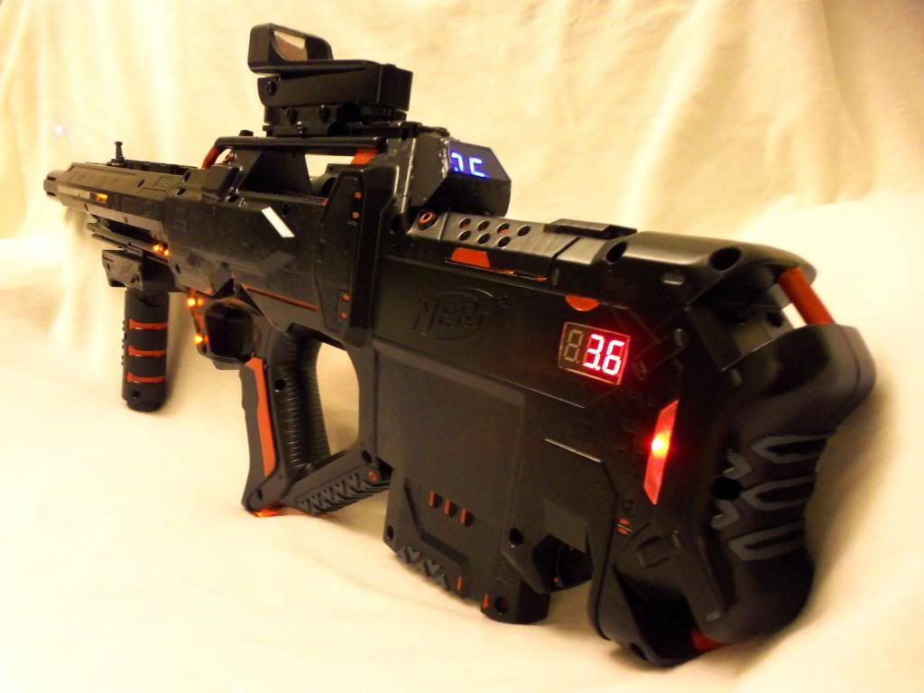
Description:
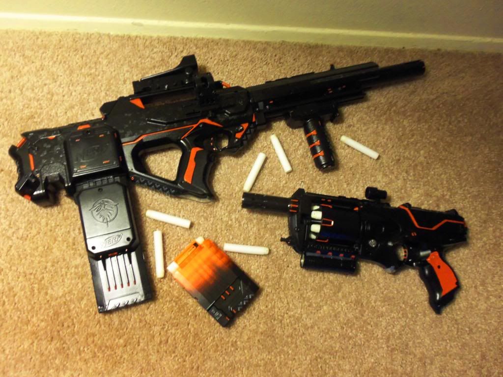
This is my 4th Nerf mod, the 3rd being the matching Strongarm. It is a Standard Nerf Elite Rayven, with a second set of motors added in front, and numerous Electrical elements. Very Smooth firing, ~100ft (+,-) 15ft range flat. Just for Kicks build, no HVZ or anything. I am more interested in aesthetics and functionality vs. practicality.
Elite Rayven:
+ 2 Mach Dash Pro 2 Motors
+ Integrated Laser Pointer
+ Digital Ammo Counter
+ LED's (with dim)
+ 9v Conversion
+ Integrated Voltmeter
+ Red Dot Sight
+ External Flashlight
+ Hi/Low Power Option
+ more....
Items Purchased with Links.
Flashlight: Cree Q5 ~$ 6 USD
http://www.ebay.com/...984.m1497.l2649
Flashlight Mount: ~$ 5 USD
http://www.amazon.co...0?ie=UTF8&psc=1
Laser Diode: $2 USD
http://www.ebay.com/...984.m1497.l2649
Batteries:
9v, AAA, Local Stores.
Efest IMR 14500 3.7 LiMN $6 USD (x2)
http://www.ebay.com/...d=111199161468
LED's ~$ 4USD
http://www.amazon.co...0?ie=UTF8&psc=1
Motors: Mach Dash Pro ~$15 USD
http://www.amazon.co...0?ie=UTF8&psc=1
Volt Meter: ~$8 USD
http://www.amazon.co...0?ie=UTF8&psc=1
Red Dot Sight: Tippmann ~$12 USD
http://www.amazon.co...1?ie=UTF8&psc=1
Ammo Counter: ~$32 USD
http://www.westaby.n...2118a8effe54f5e
(Emailed and Asked for Custom Configuration, has 3 mode option. I chose 6,12,18 clip size.)
Paint:
Testors Orange, Black. ~2 USD Hobby shop
Flat Black Vinyl Die (Credit to Coop772), $8 USD Auto Zone
Rust-oleum Mat ClearCoat ~$5 USD Local Hardware Store.
Resistors, Dimmer, Switches, Wire, all from Radio-shack.
http://www.radioshac...lue=under $3.99
http://www.radioshac...oductId=2062339
Other Materials:
Hot Glue, Epoxy, 1/8" Plexiglass, Small Hinge, Hardware, All form Local Home Depo/hardware Store
Other Nerf Accessories off Ebay.
Nerf Rayven AND STRYFE. I used the Stryfe strictly for its motor case, and scavenged a few other parts.
Sources and Credit Links
http://nerfscience.b...ite-rayven.html
http://nerfhaven.com...showtopic=21973
http://modworks.blog...nals-guide.html
https://www.youtube.com/watch?v=oP067x8Vj20
https://www.youtube.com/watch?v=0DGFTem-Wfg
High/Low Selector Topic http://nerfhaven.com...48
Nerf Haven Search http://nerfhaven.com/googlesearch.html
Final Product Link:
http://nerfhaven.com...ic=5250&st=4635
Display/Show Video Link:
*In work, Coming Soon*
Full Pictures Link:
http://s818.photobuc...nkXV/slideshow/
How I did It:
This is my first Write-up, so please excuse any missed points or lack of detailed instructions like I've seen elsewhere. Most of what was done was shell carving to fit and Wire management, neither requiring high-end skill. I do not have a ton of WIP pics to show, however, it really is all trimming to fit, and this is merely a guideline/description of how I did it. Many Thanks!
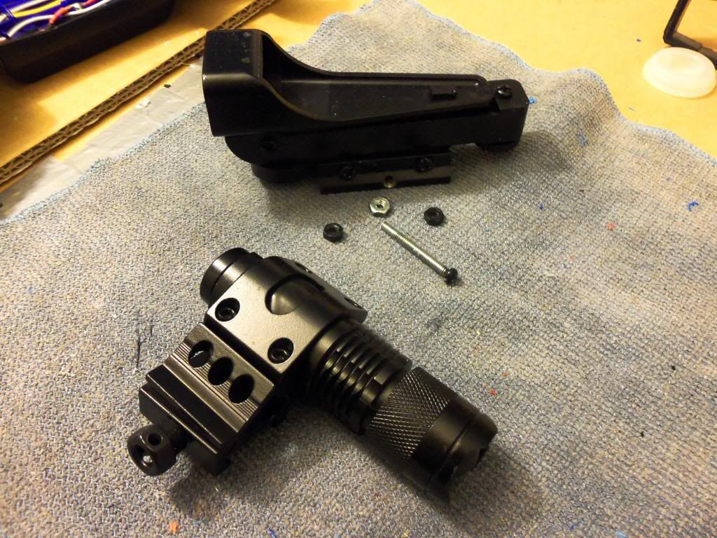
1. Flashlight
The flashlight and mount are relativity simple. I personally would not recommend the light I purchased, as I am a mechanic by trade I use many different flashlights, and honestly, my local Target has 9LED (3 AAA bat) Lights for $1 USD (as seen in pic, other one hadn't arrived yet). I've bought about 7 thus far. (Used on Strongarm) They are easily bright enough for nighttime use (indoor or outdoor), and compact enough for integrations. The light Mount is a rail clamp type, and was initially loose on the side rail of the Rayven. I dripped epoxy into the top and bottom of the rail, filling it then sanding it flush. This gives enough for the mount to clamp onto, and holds rather secure when tightened. This Does not render the rail useless, and Nerf Tach-rail attachments still work perfectly. It may be required to wrap the flashlight's barrel to widen its Dia. so it will fit snugly in the mount.
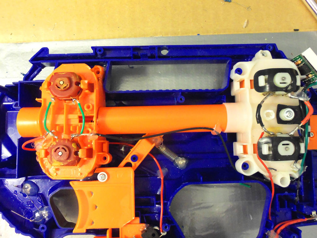
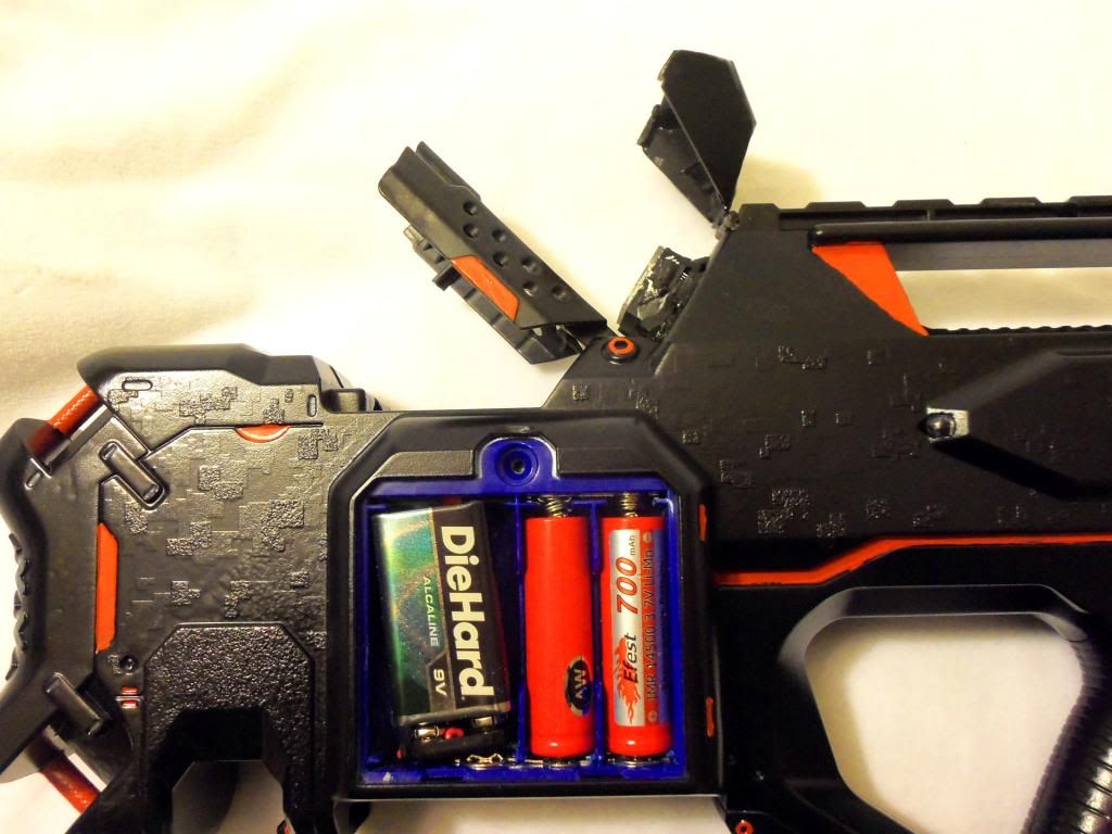
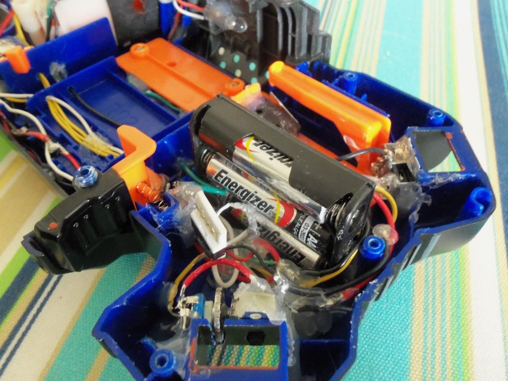
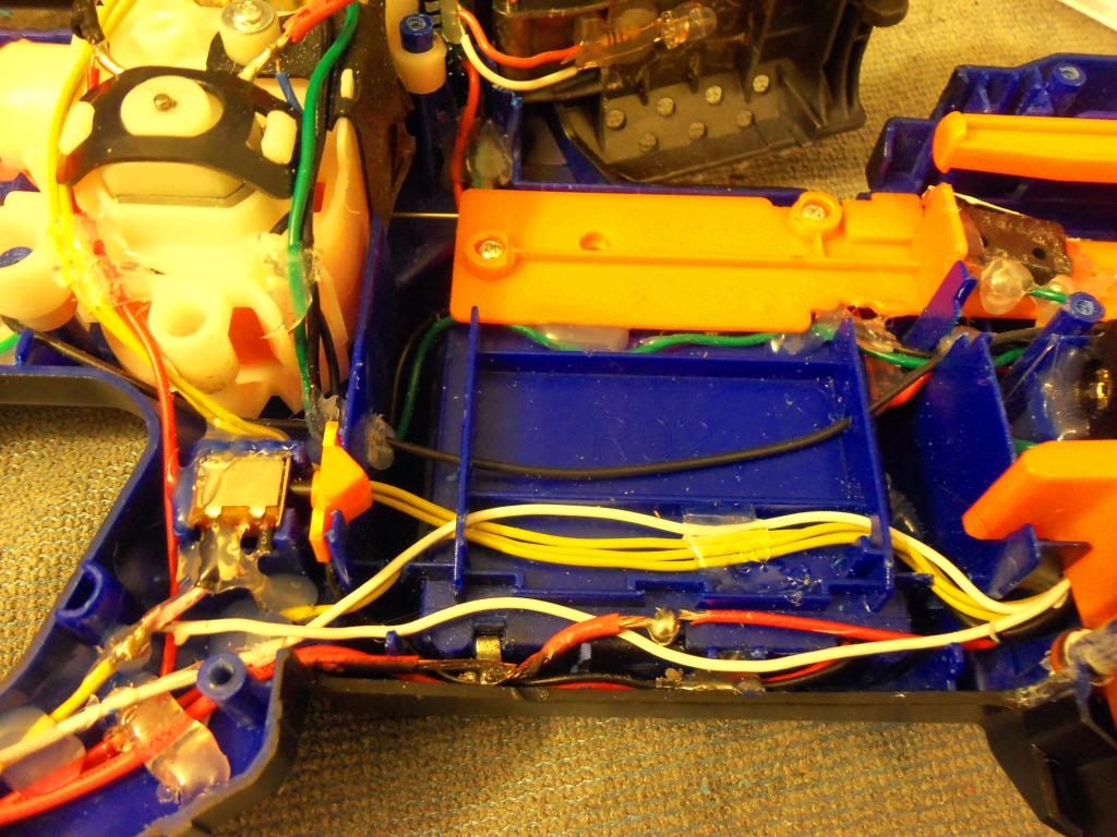
2. Motor Power/Batteries
Forward Motors run off 2x 3.7v, paralleled, housed in the battery tray which has been edited to allow for parallel orientation. (Efest IMR 3.7v rechargeable) A 9v also runs the first set of motors, and with trimming of the battery cover, fits snugly in the battery tray. Wires are run out to their respective locations. All other components run off a x3 AAA holder nested in the rear of the shell. This battery pack came with the Ammo counter Kit, however different trays can be used as needed, Please note that a x4 AAA will be a tight fit depending on where its placed if inside the shell. For the accessories bat. pack, I used the main leads of the pack as a hub, and striped about 1" of the coating off the wire, and soldered all power wires to that location as needed, repeating for the ground.
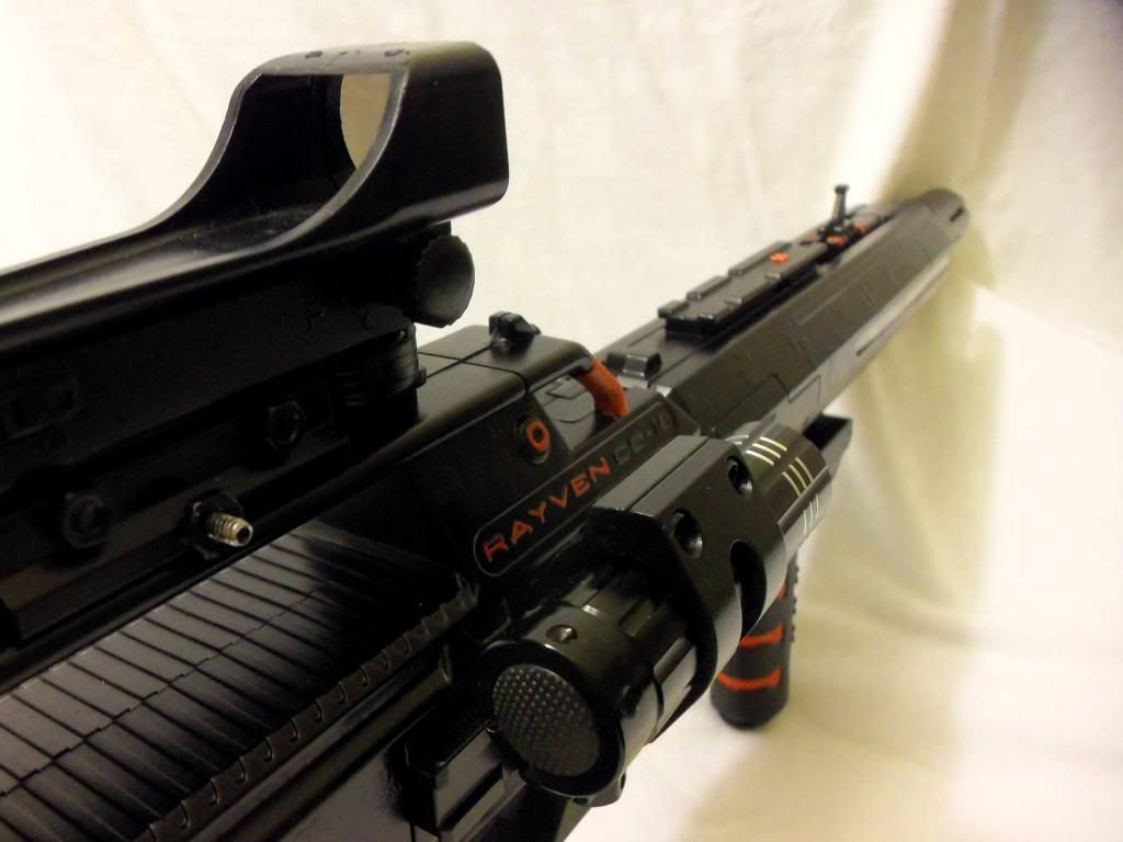
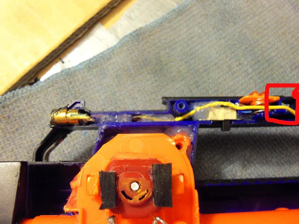
3. Laser and Red Dot Sight
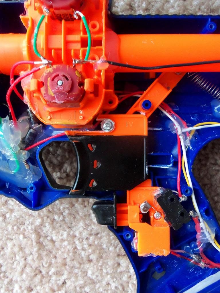
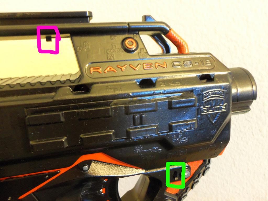
The Laser and Red Dot Sight are both synced the best I could, however the sight itself has adjustments. The laser diode is nested into the shell at the top just in front of the rail. The Diode I received runs about 3v, but I used the same resistors I used on the LED's, 100ohm Resistors, so it runs a little lower voltage then rated. I used my drumel to carve straight into the shell while it was assembled, and carved as needed. Placed the switch directly behind that, and routed the wires through the top. After I got it soldered and working, I put quick-dry epoxy around it and closed the shell with it powered, then held it in place when it was centered till it dried. Then filled the voids and smoothed the shell with more epoxy. For the Sight, the clamp was similar to the Light Mount, but it was simpler to just to drill through the sight while I held it in place on the rail, and affix it with a bolt. This holds it really solid and flush. You can see the hole through the top rail just behind the spring clip (Red Box)
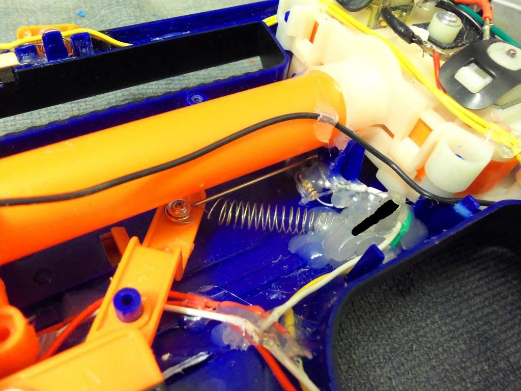
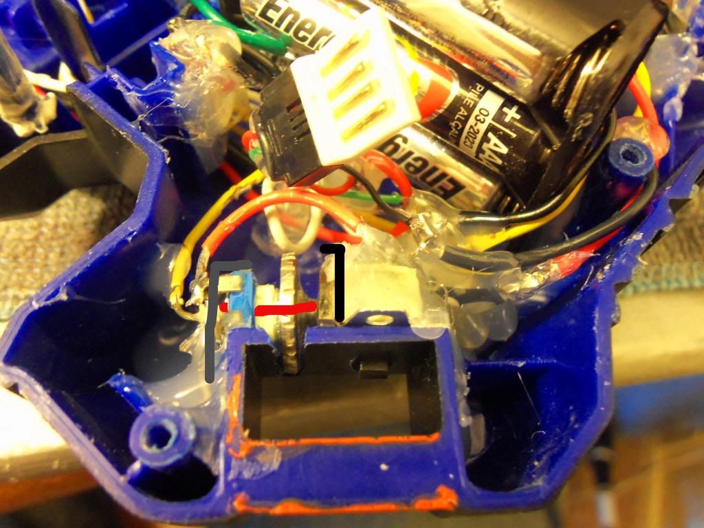
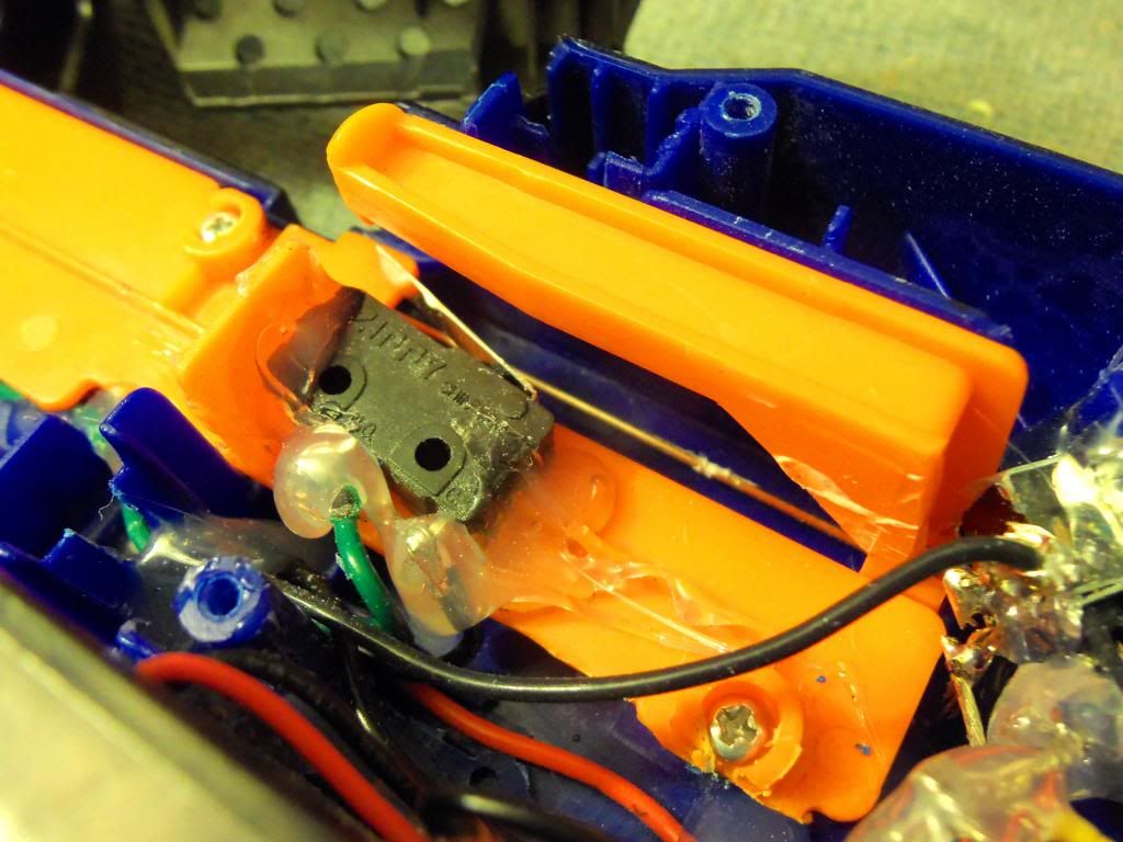
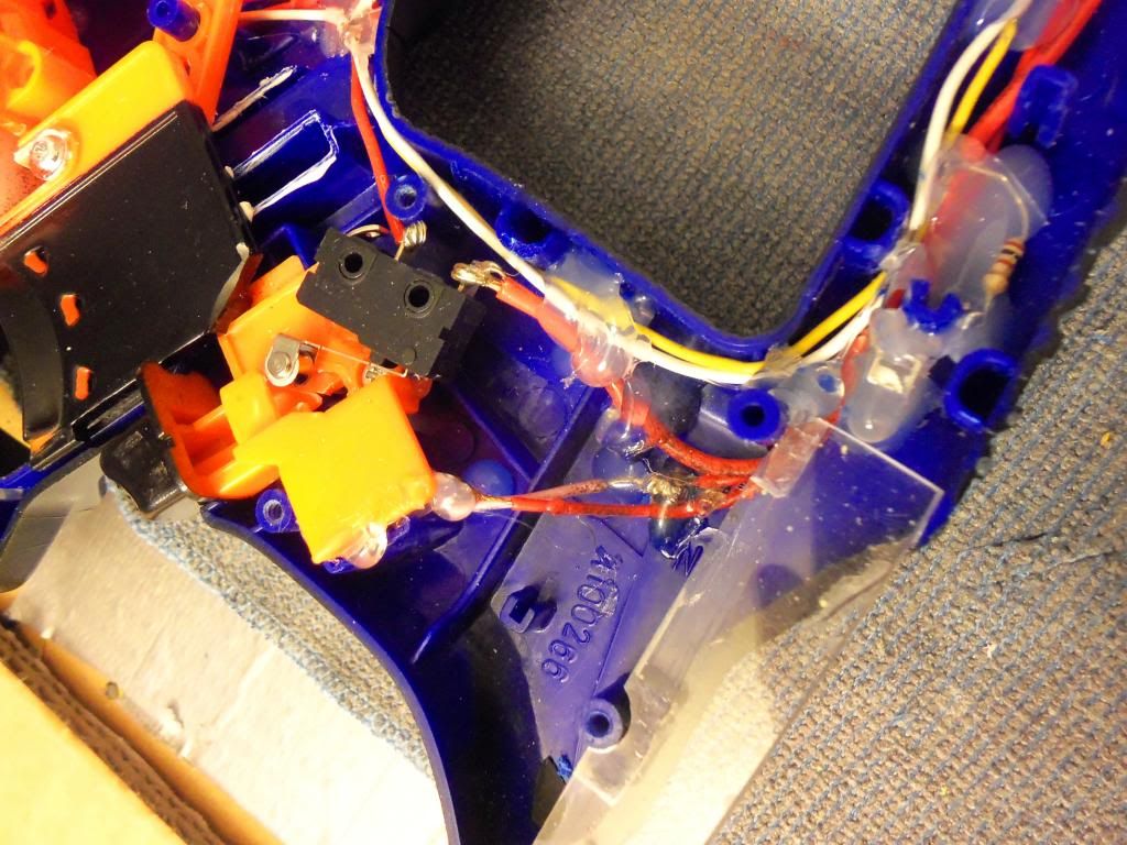
4. Trigger Mod
Picked up a spring from my local hardware store, nested it as seen to smooth out the trigger pull. I first glued a small 3/4" bolt head down in the shell, and hooked the spring on that. (Black line illustrates position of bolt)Then excessive use of hot-glue to secure it. Also cleared away the shell around the pull wire.
5. Gun-Barrel Terminals, High/Low Function
I like using the barrel extension as I take appearance over functionality. I ran LED's in the bar.ext. but with no power source, all parallel, and routed the wire to two flat terminals at the base of bar.ext.
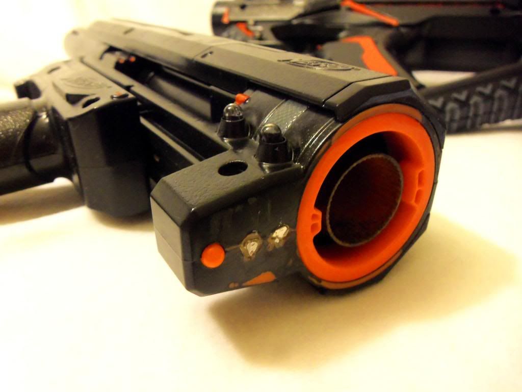
These meet up to matching leads on the main gun. All LED's are ran parallel, so breaking/completing this circuit has no effect on the total unit. Simply attached the barrel, and it will light with the rest of the gun, remove it, and the gun still lights with no extra effort.
The main body terminal have a little bit of spring force, thanks to the how the wire are ran. I cut small ports for the wire to slip through the shell, one above the other for the two leads, then put strict 90* bends in said leads, routing them straight down to other LED's in the area. Cutting exactly, I was able to lube the holes cut in the Rayvens front 'barrel' piece to allow the terminals to exit, with it all lined up, the terminals hold place just beyond flush, but when the bar.ext. swings in, it pushes the two terminals back, using the wire and the 90* as the spring, then there is just enough force to make a solid electrical joint when the bar.ext. snaps into place.
Under that heap of glue is a small SPST Switch, one that handily came with the Ammo Counter Kit. This switch serves as a high/Low power switch for the forward motors. Easily accessed by the trigger finger, (See switchbank pics at bottom) up is full power, and down routes the circuit through two diodes (See source link for info on what diodes) to limit the power going to the motors, giving roughly ~50% power. Big Difference.
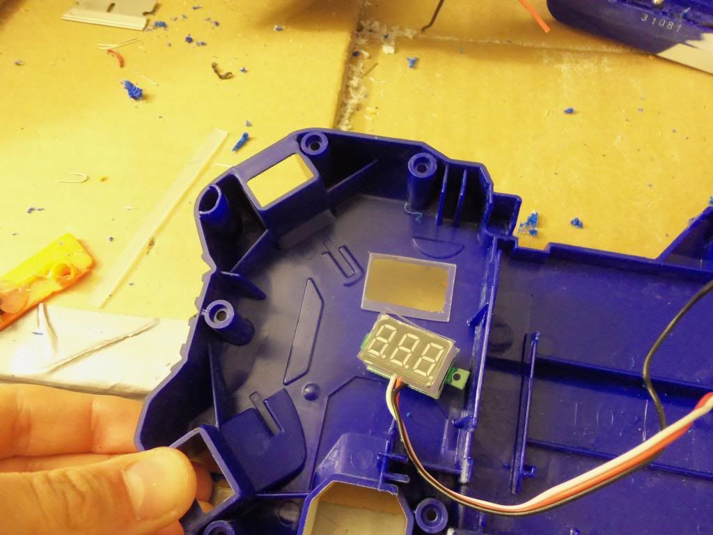
6. Voltmeter
Simple voltmeter is attached to the battery terminals of the 3.7v batteries to give an accurate rating of how much power is remaining, and when they need to be charged. The voltmeter is nested on the reverse side of the shell, with the switch, and is viewed through a piece of pexiglass mounted in a rectangular hole cut in the shell. Fairly simple.
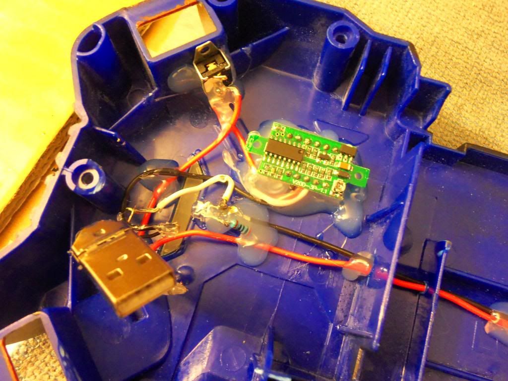
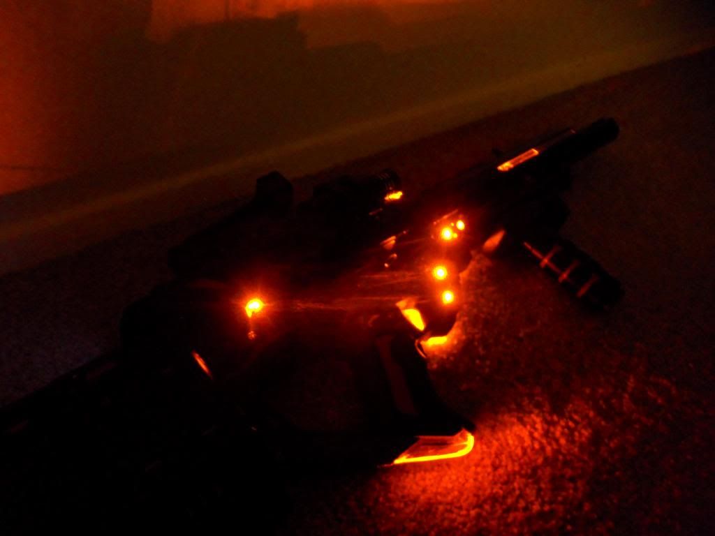
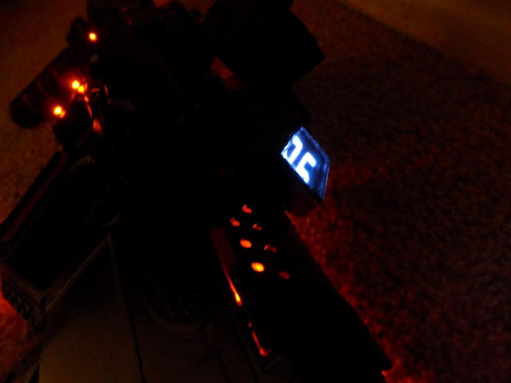
7. LED's
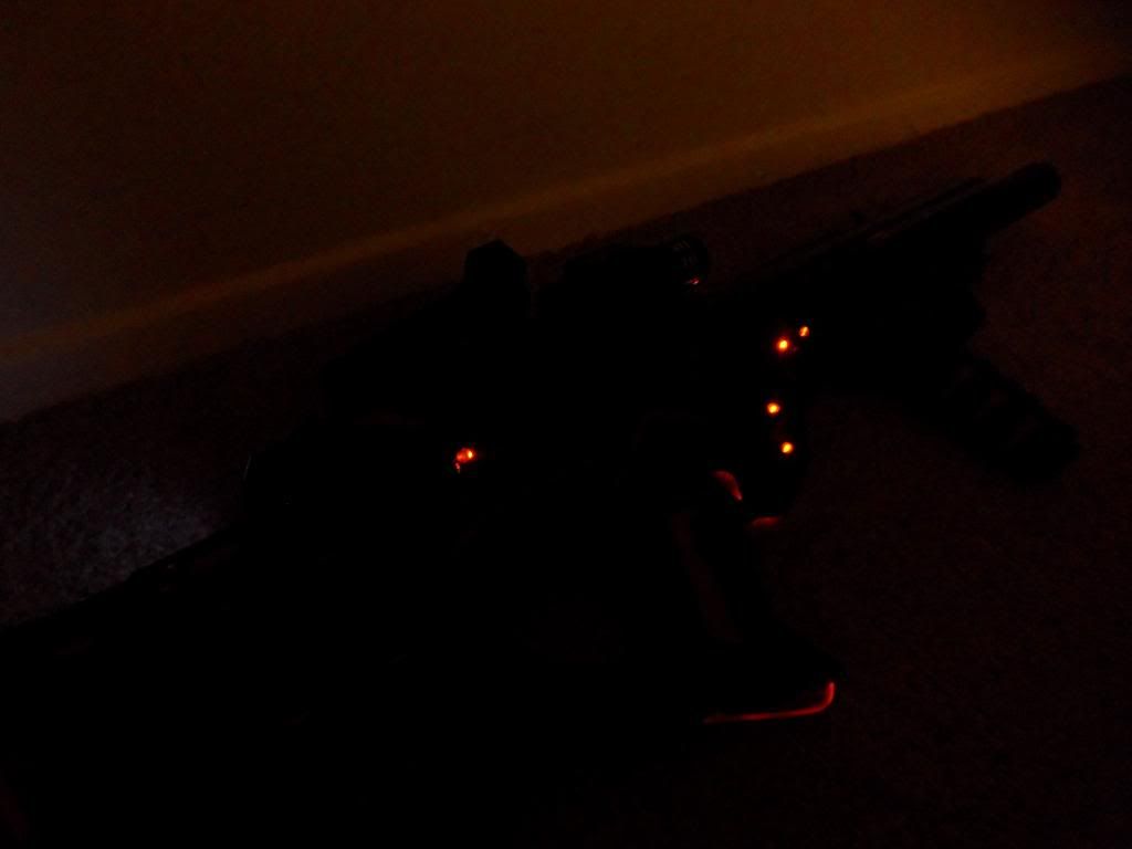
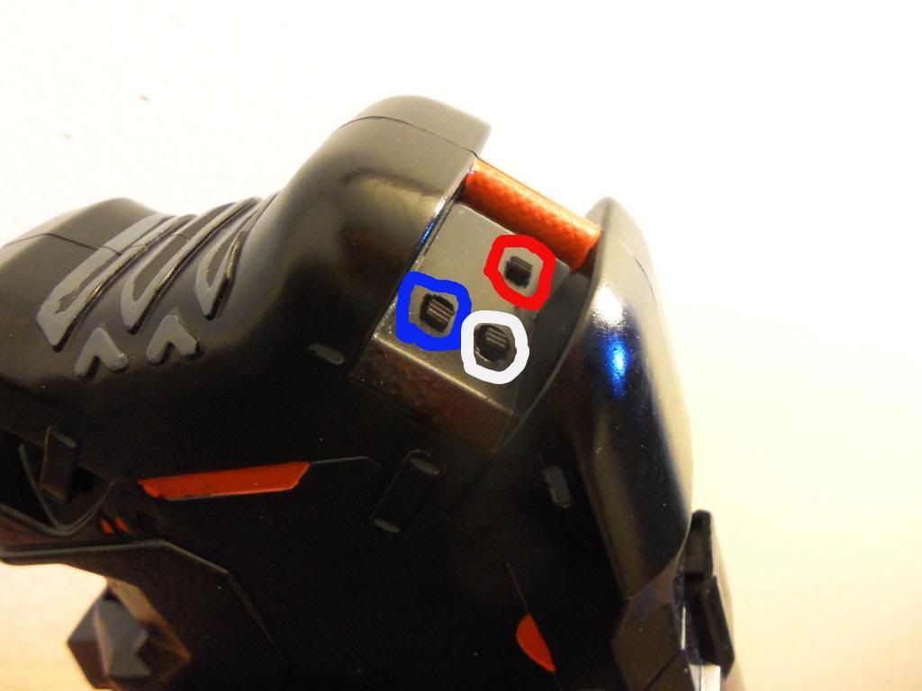
There are a total of 7 LED's in the lighting circuit, 15 if you count the bar.ext. 2 in the very front on both sides, 1 on the O/B side pointing aft, 1 in the bottom grip, lighting the Acrylic, 1 Red LED in the far back on the I/B side lighting a body cutout. 6 total in the bar.ext., 2 facing forward lighting the pexiglass rails, and 2 on each side facing out matching the two in the front of the main gun. All LED's run off the same 4.5v 3 AAA bat. pack in the rear. The LED's used are rated at 2.2v, my source is 4.5v, so I used 100ohm resistors for each LED, plenty for good life and brightness. There is a On/Off switch in back, right next to a dimmer. At full power these suckers are bright, and easily light a pitch black room with Effeminate orange luminescence. However, with just a turn of the custom dimmer wheel, they can get very dark, still lit, but very dim, perfect for some awesome sci-fi sneaking. The dimmer was one of the hardest things to do. I wanted a wheel, but the device had to be tiny to fit in the now cramped rear shell. Radio-shack does not have a specific listing for to link too for what I got, however it was the smallest 3-prong blue potentiometer (pot.) they had. Using a typical nerf screw from the mag lock, (the small chrome ones with the built in washer), I glued a washer (custom knurled with cutting wheel of drumel) to the base of that, and countersunk the head of said screw into the tunable part of the pot, making sure to keep it level as possible. I then slotted the shell and mounted it, being sure to keep everything clear of the spinning parts. Very much Trial and error, several attempts and ideas here failed. For added security due to the lack of adhesion surface, I cut down a much larger washer and used it as a bearing to catch the shank of the screw stuck to the pot., and prevent it from being pushed inward, as well as thick hobby wire to hold the assembly in place.
Black indicates area of cut washer to act as bearing. Red indicates rotating area, Gray illustrates wire hold down.
Added Trick. I've played a ton of Borderlands 2 (X360), and from that and other sci-fi themes, I like that weapons draw power from the clip. Miliwan weapons specifically. (For reference, view this vid from 0:35-0:41 to see reload animation http://youtu.be/bCwwBY_SLzA?t=35s ) So, I added this affect by keeping the electrical clip lock in the shell, but re-purposing it as a pressure switch for the LED's. Basically, LED's won't light unless a clip is inserted. As you insert the clip, the knob on the sensor switch passes the lock point on the mag as well, and creates a sort-of flicker effect briefly like seen in the vid or in-game. Works double duty as a safety to prevent unwanted dead batteries.
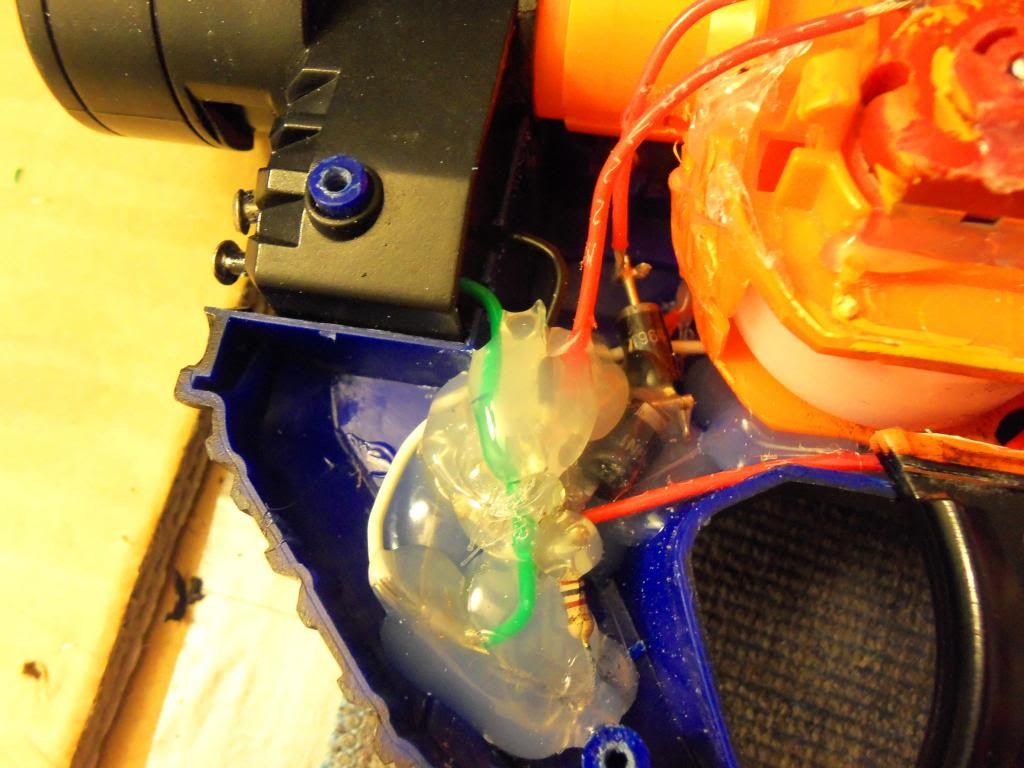
8. Shell Connections
A Scrap USB cord was used to connect the two shell half's electrically, to ensure that maintenance would be as simple as taking the screws out. There are 4 wires the ran across to the other half of the shell, and a USB cord could be minimized to work well. After removing all the excess 'rubber' coating, I removed the metal casing from one end, and sanded down the Teflon to gain access to the ends of the 4 leads. (as seen in Dimmer pic above). It was needed to sand them down, as there was not enough force to make the connection secure while minimized, so simply sanding it down and lifting the 4 terminals ever so slightly, a secure and good electrical connection was made. 2 wires for the voltmeter, 2 wires for the LED's. You can see the 'female' end in the battery pic listed above as well.
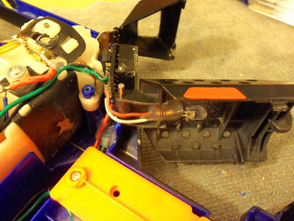
9. Ammo Counter
This was one of the must have items to put in this blaster, and easily the most time consuming. I will say right from the get go however, it really was a straight forward install. The Kit has mostly everything, if you email the vendor where I ordered mine, you can set custom coding for your unit, and he was in constant communication. Instructions can be found online, but for a basic wiring guide I viewed his Flikr page for this image. ( http://www.flickr.co...66782/lightbox/ ) I chose 6,12, and 18 round clip sizes, counting down by one each time, however it comes stock with auto, single, and 3rnd burst. Its is literally as simple as placing batteries, display, and 3 switches.
The System operates with a power switch, counts down by one with the activation of a momentary switch, and resets with a SPST switch. The 3 modes are rotated through by depressing the trigger switch, then the reset button simultaneously. The kit comes with a lever switch for the trigger, which I found to big for this use, and picked up a smaller one at Radio-Shack for 2$ USD. I placed this where when the dart pusher if fully forward, it depresses this switch, and slides back releasing it, indicating one round used on the counter.
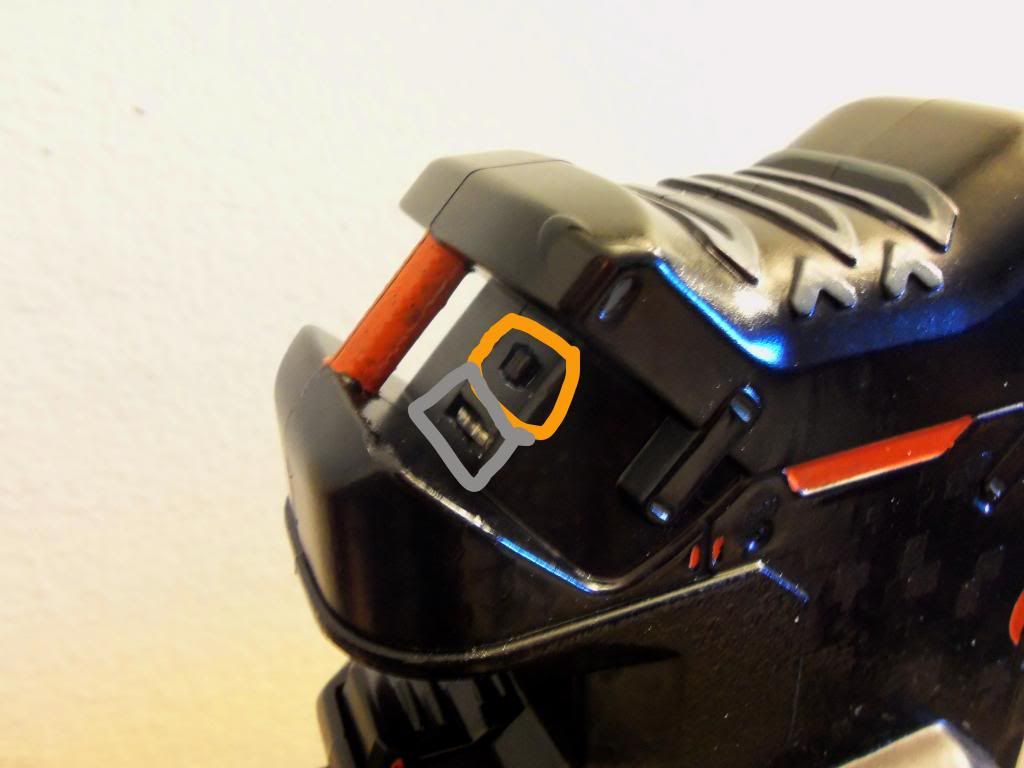
The Reset button was also swapped out for one of the original electrical lock switches from the original blaster, (jam door lock), and was placed in a position where when the mag release button is pressed, it resets the counter. This is perfect because when there is no way to reset the counter unless you remove the empty clip, and its ready when you insert the next. If its a different size, hold down the trigger prior to inserting the clip, and while inserting the clip, depress the release button 1-3 times to quickly cycle the round count. This can be done much more quickly then it sounds. I did find however that the release button wasn't making solid contact with switch, to fully depress it as needed. This was solved by gluing a small bit of rounding plastic to release button, giving it the reach required.
Black is added plastic piece, Gray is re-purposed switch.

On/Off switch was placed in the switch bank, and can be seen below.
The 3 clip modes can be seen in the Picture Slideshow link at the top.
The Display was placed just in-front of the jam door bay, as was the only practical area for it to fit well. This was very tedious fitting this thing in here, and required both major trial and error trimming on shell while assembled, as well as light sanding on the display as well. Wire management was also a huge issue, as there are 6 wires to be ran to their respective switches, and with the first set of motors right there, I could not place it very deep, and the dart passage space right in the middle, I had to route 4 tight below, and 2 wires above the motor case (green and black)
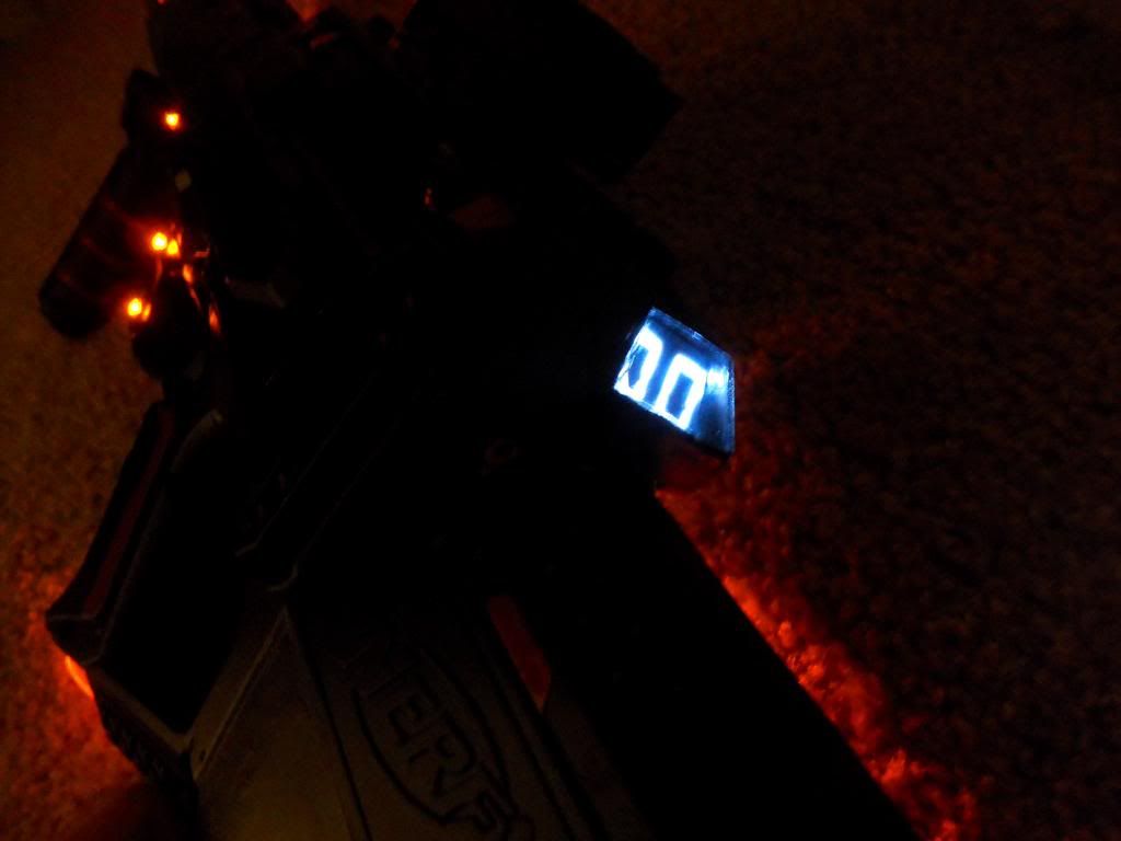
I knew from the beginning I would be encasing it somehow, as a sleek look as well as some protection for the display was a must. I did this by building a 'doghouse' over the display and attaching it with a hinge mounted in the shell, to allow it to open up for cleaning, ext., but as well as full movement of the jam door. The jam door with the doghouse closed opens roughly 80% its original angle, but not 100% non-the-less.
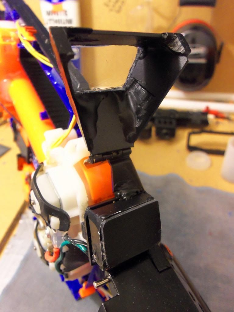
The Doghouse like many other custom pieces where cut and trimmed out of 1/8 plexiglass. The material I used I salvaged from work, and in all used maybe 6sq" total. The plexiglass is rigid, but brittle, both can be used to your advantage when sanding. Simply score a line with an exacto where you want your cuts, and gently pry along one line at a time with a pair of pliers till it snaps off. With 320 grit, it is easily sanded for rounded or angled edges, so alignment with other pieces can be done. I got my rough shape set up, 2 sides, top and bottom, and lightly held them in place with small strips of masking tape. Once I got my rough shape set with tape and lined up, I dripped epoxy along the edges one side at a time until the 4 sides became one unit, then removed the rig from the blaster and filled in the final edges to be sure its good and strong, taken note not to get any epoxy on the shell OR the display, as everything was in place to do this. Then, I added two very small bottom pieces, and a lower cover to help match the jam door and strengthen it.
The final clear piece wasn't glued on till after the assembly was painted with the gun. This was very time consuming, and contained several hours of sanding, fitting, gluing, waiting to dry, ext. The hinge was found at a local hardware store, supposedly decorative, however I sanded down the curvy and frilly edges for a more angled look. I did have to trim the sides of the hinge, as it would otherwise of been to wide for this application. The pivot point itself remained the same. I did have to trim the inside of the doghouse upon final assembly to fully clear the display, and in doing so, left the tiniest amount still rubbing, which gives the doghouse a locking effect when closed, which works very well, and will not open unless pulled.
The display that comes with the kit is white, and Extremely bright. Way too bright to leave as is, so I took more plexiglass, fitted it to the size of the display, and lightly dusted black spray paint till the desired 'dim' was achieved. This could probably be done with automotive glass tint or something of the like, however $12 a roll when I only needed 1sq" seemed irrational.
Added Trick. The display has two optional LED's (as seen in wiring Flikr link above), which you can specify if you would like removed or not. I requested them to be removed, however (due to an initial programing issue, which was corrected by sending me another display free of charge) my final display still had one LED on the side. This one remains lit until the counter reaches 0, when it then goes out. After much consideration, and not wanting to fully remove it, (just snip it off otherwise, no harm done), I replaced it with one of the other orange LED's, (the original was also super bright white, and ran 3v.) and placed the orange LED in the roof of the jam door, trimming the jam doors bracing to allow for better illumination. This gives the jam door bay an orange glow whenever the counter reads anything above 0, and nothing when empty. Basically, if its got ammo, it glows, no ammo, no light. A sneaky way to tell if the gun has ammo or not if viewed from the side or if the display is covered. LED can be seen in pic above.
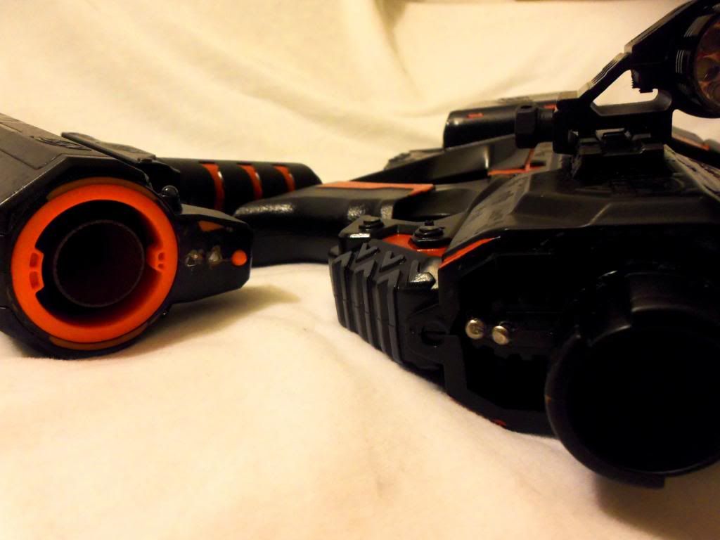
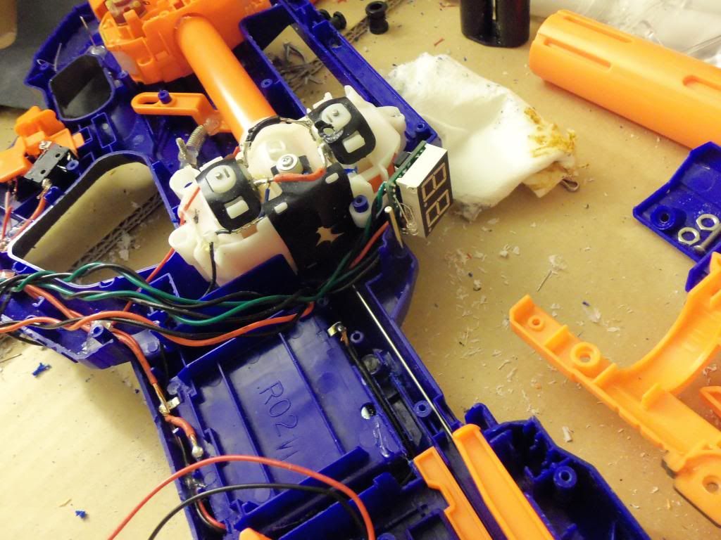
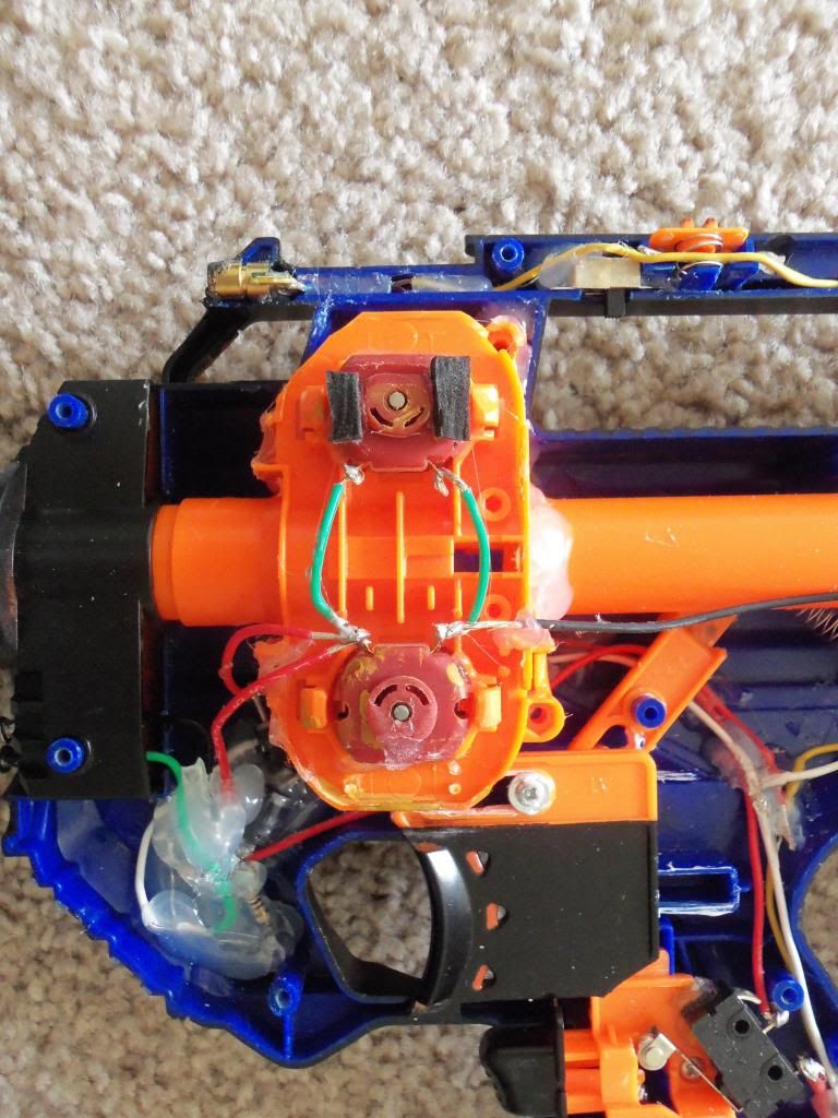
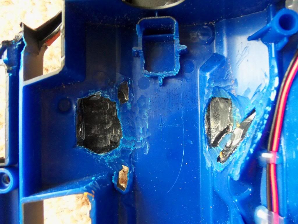
10. 2nd Motors
Really the driving force behind the entire build. I wanted to really dive into an electric project and go all out using ideas I've seen online, and try to combing them all into one awesome piece of work. The Motors are Mach Dash Pro 2's, and came as double axle, requiring one to be side to be cut off. Power is routed through a master kill switch in the switch-bank, then to a lever momentary switch seated near rev switch. With a little trimming, I was able to cut a groove for it to fit nicely, and with a gentle touch can rev the first motors separate from the front motors. Power is then sent to a third switch, which controls the Hi/Low function.
The motors are mounted in a Nerf Stryfe motor case, which fit fairly well into the front of the Rayven, which is just asking to have that void filled. It all comes down to fitting and cutting. A good 35% of the total time spent on the project was trimming, carving, cutting, all to get the motor case to fit, and be aligned. I wanted as clean as a look as possible on the outside, and knowing I would have to cut the shell to fit the second motors in meant I carved as little as possible at a time. The lower motor barely showed through the shell, and I was able to cover the exterior holes with two plexiglass pieces, trimmed and sanded to try to follow the body lines of the blaster. Any voids or gaps where filled with epoxy and sanded to make flush, sealed, and smooth. The upped motor jetted out about 1/8th" from the shell, so roughly a 1/2"sq hole was cut to make clearance. The cap for this was carved out of the same window piece as used for the 'Blade' in the grip. It is very much a cap, and was sanded and sealed using the same technique as the lower cap, while trying to match other body lines, and be as un-protruding as possible. To avoid making this to long, please refer to the slideshow link at the top to see all the pictures taken, (100+, 30+ internal detail shots) to see where was trimmed.
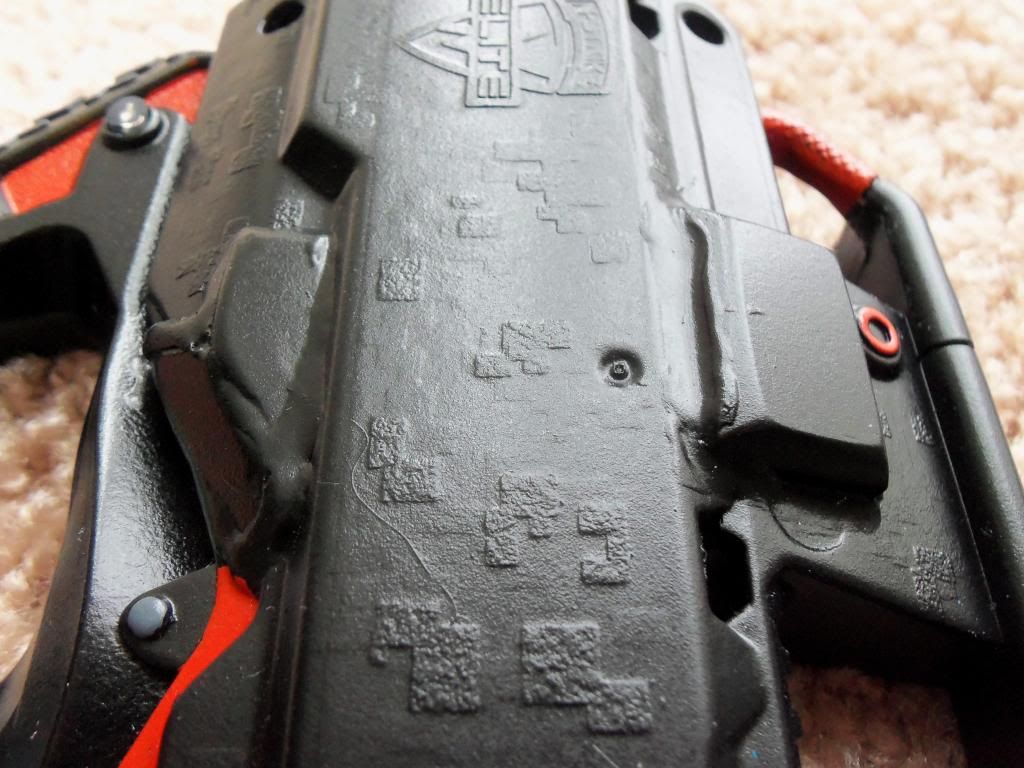
11. Paint
The paint is flat black vinyl die, as referenced and used by Coop772. I will admit I was surprised by its adhesion, however it is nothing extreamly special, and at $8 USD a can, it is quite expensive. (I scored 20+ cans of multiple types/colors of Krylon spray for less then 20$ Black Friday last year at a local hardware store. 75 cents a can. XD) The gray is basic ghost gray by Testors, and the orange is a custom mixed color, with red, orange, and black for the desired color, and it came out exactly how I wanted, a nice deep red-orange. A mat finish Clearcoat by Rustolium was applied, and gives it a slight sheen, much to my liking.
12. Switchbank
Front Motor Power:......White
Voltmeter Power:........Red
Ammo Counter Power:.....Blue
Laser Power:............Purple
Hi/Low Motor Switch:....Green
LED Power:..............Orange
LED Dimmer Wheel:.......Gray
Final Thoughts:
I am in all Very happy with the result. As I was working on this for well over 2 months, waiting on parts and massive trial and error in some places, just having it finished is great. I'm most pleased with the LED's, their overall brightness, the effects, and how dim they can go surpasses my expectations. I'm also pleased with my doghouse cover, and how it locks in place, and meshes with the body lines of the blaster fairly well. If I hadn't rushed myself to get it finished, a little more time sanding the epoxy on the caps and the doghouse, as well as general fit and finish would have gone a long way. It also has a little less power then I was hoping for, and isn't very accurate due to not 1005 aligned flywheels from motor set to motor set. Regardless, without attempting to sound arrogant, this is the most loaded Rayven I've seen, and I am very Pleased.
Many Thanks!!
Especially to azrael for a ton of help with a few electrical questions I had.
Fun Facts:
The piece of plastic used to extend the mag release/reset switch actually came from my laptop. Now, this seems insignificant, however, my laptop is going on 9+ years, and has a huge nostalgia factor since my entire high-school, college, and now working life was spent with it. It come from the vent in the back where the fan outlets, and I had no idea it was broken. After a few hrs tinkering with the counter and such on the gun, I stopped for the night, and before siting on my couch with my laptop for some browsing, I saw this little black piece on the ground. I knew immediately it had broke at some point and where it came from, but that was irrelevant, as it was the exact perfect size and shape to fix my reset switch issue.
The 'blade' as I'll call it, in the grip of the gun which is clear until lit with the LED nested behind it is actually acrylic from a 747 window. I work as an Aircraft mechanic, and when a window is bad, we usually keep the old one around and make scrapers or whatever out of them. I had just happened to be thinking of ways to illuminate that area of the gun while at work, and low-and-behold I opened a drawer in my toolbox and there it was. Needless to say, later that night it was cut and trimmed to fit.
I built the Strongarm first, as I was waiting on parts for quite some time for the Rayven. The LED's and Paint are the exact same, however with the Strongarm I added some exterior items for the sci-fi look. Batteries, Custom cut PVC barrel ext., and different sight. LED's run off 2AAA for 3v, and a toggle switch hidden in the base of the grip. Flashlight is simply glued to the bottom. I am very pleased with the matching effect, they look and work great together. Pics of the Strong arm can be seen in the Full picture list at the top.
(tl;dr Awesome nerf quad Rayven with much electrical goodies + pics)