Find content


Hey guys, I'm SoftButFirm. This is my second tutorial and I hope this helps you. I know people have done this before, but I didn't find a lock removal mod on this site. So maybe this can make it into the directory as a lock removal tut. Also, I know this is fairly simple, but all the wiring from certain places might mess some people up, that's why I'm making this.
Enjoy

STEP 1 - GET YOUR SHIT TOGETHER
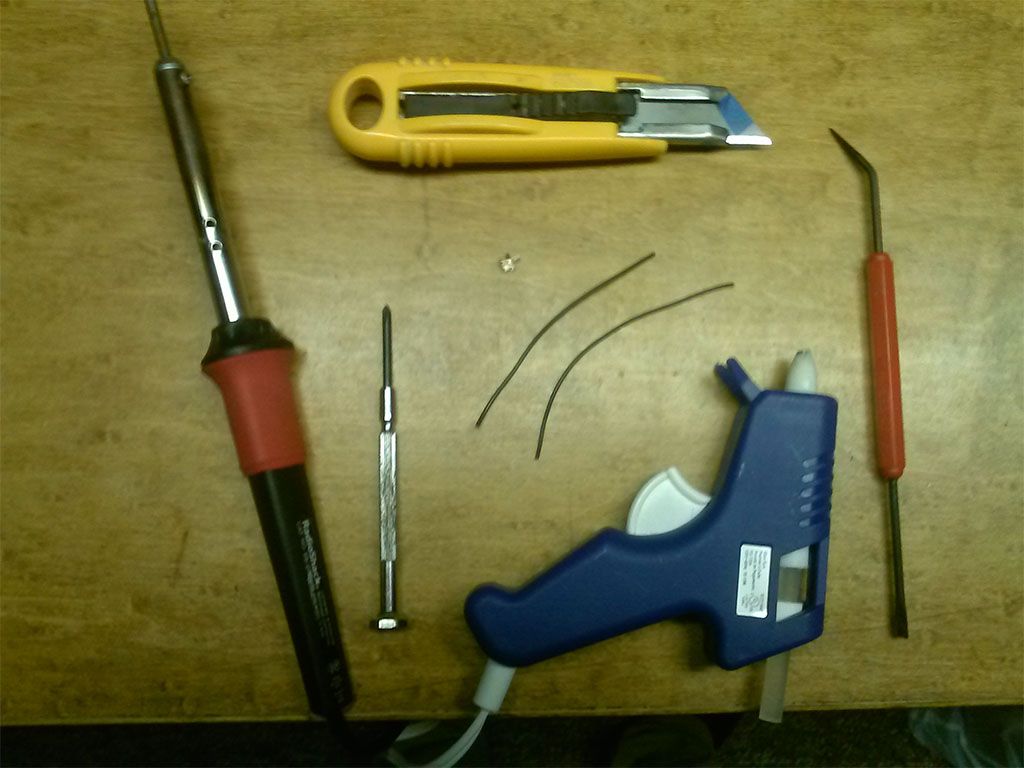
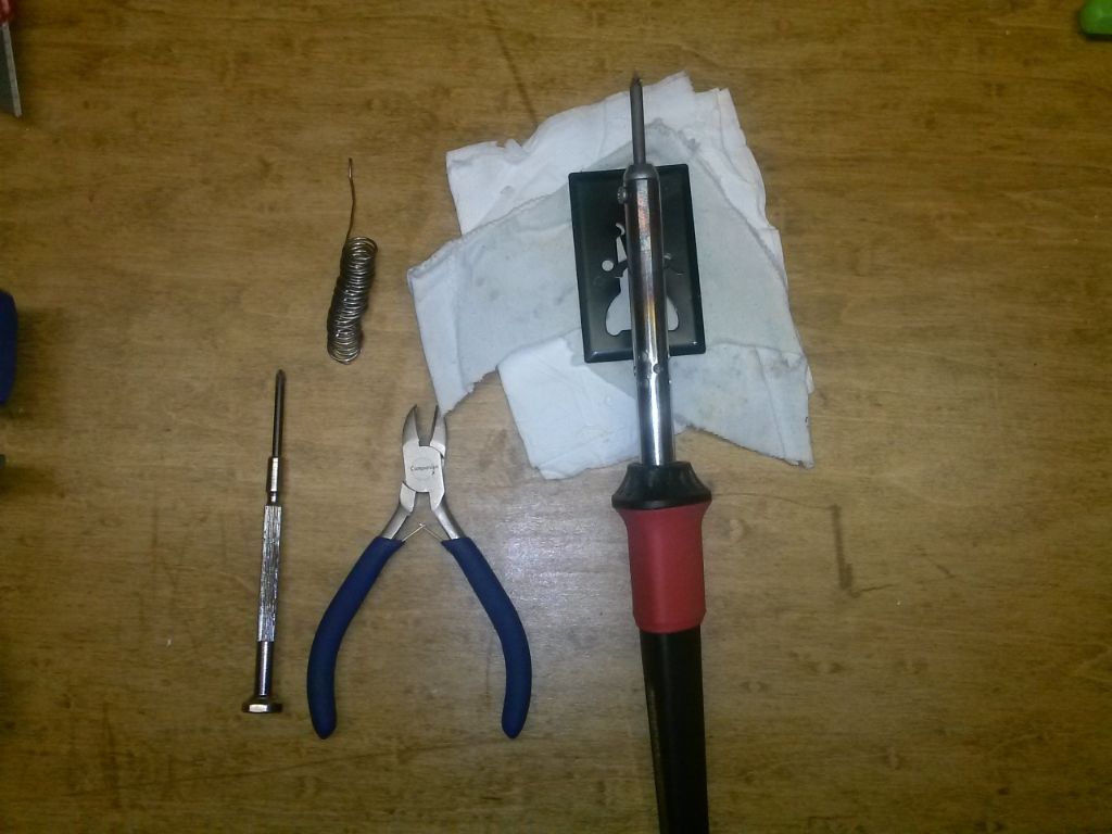
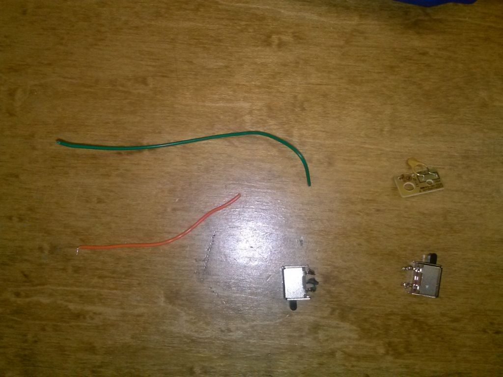
What you need:
1. Screwdriver
2. Something to cut wire
3. Soldering iron and solder
4. Wire strippers or a sharp knife (Not pictured)
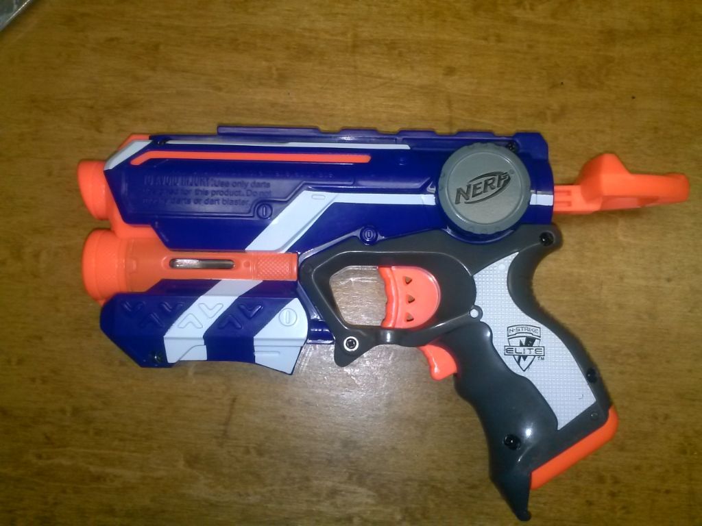
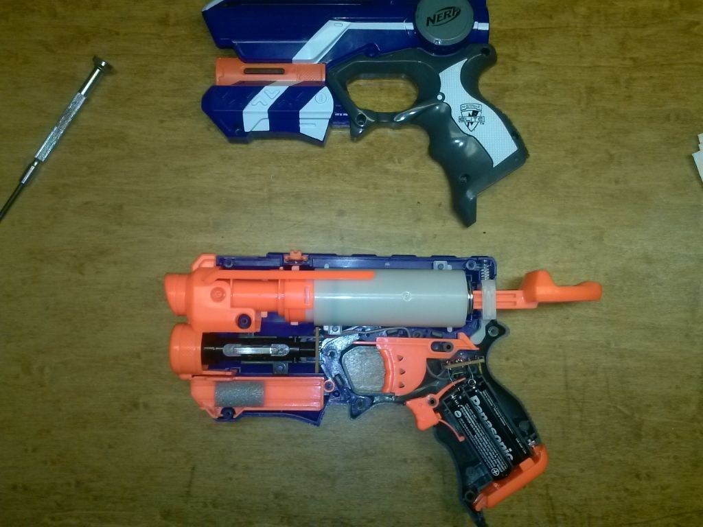
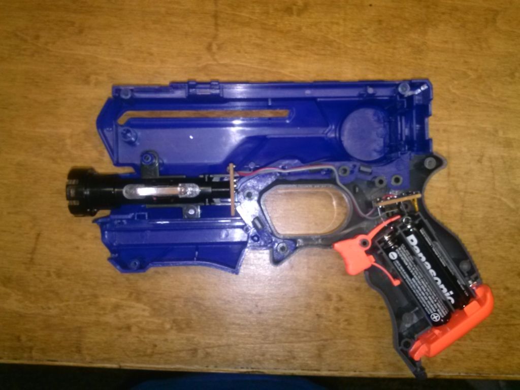
STEP 2 - OPEN THE BLASTER
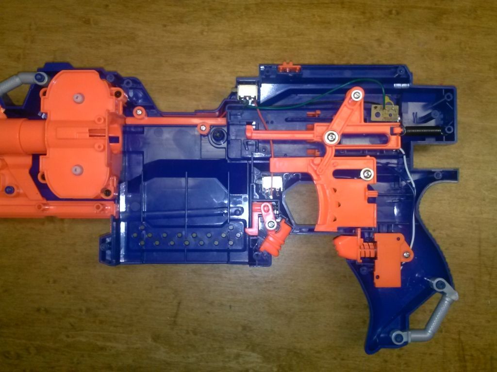
Your gun should pretty much look like mine. I have mechanical locks removed, but I'm not showing how to do that because it is easy to do yourself. If something won't move, find what is blocking it and get rid of it... Simple.
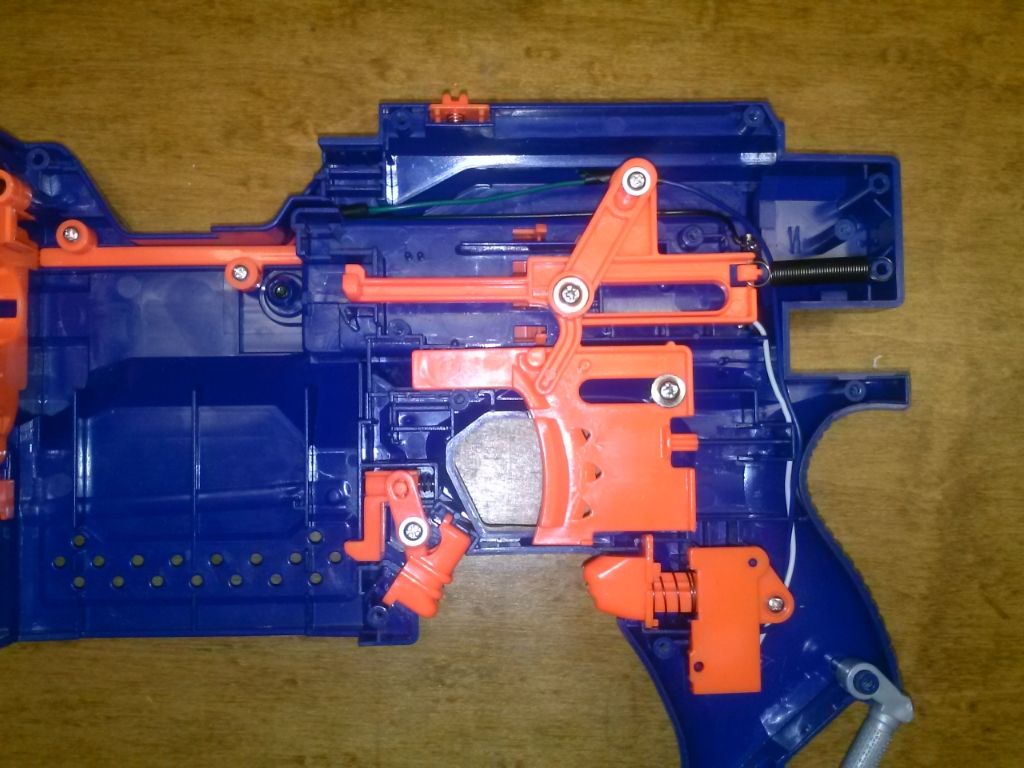
STEP 3 - REMOVE TRIGGER AND DART PUSHER
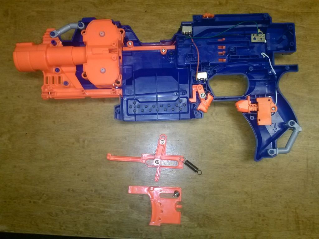
Take out the screws that hold these pieces in place and take the sping off the back peg. Then take these pieces out and set them to the side.
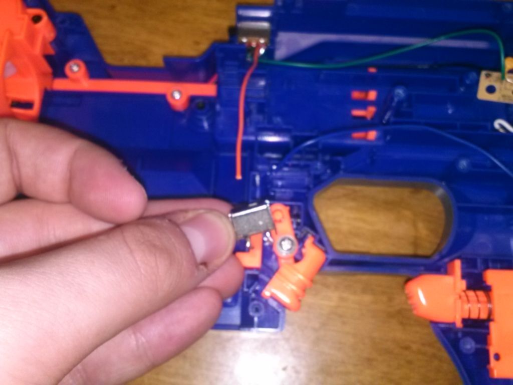
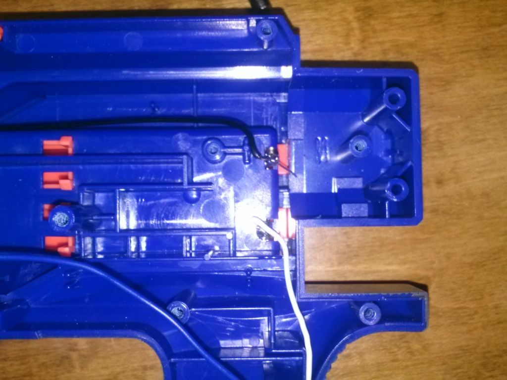
STEP 4 - REMOVING THE CLIP LOCK
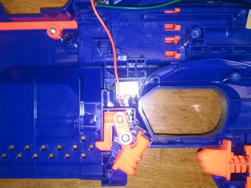
There should be an orange plate covering this button, along with a mechanical lock that prevents the trigger being pulled if there is no clip in the blaster. Get rid of it all. On to the button - There should be two wires going to it, a blue one and an orange one. Cut them both at the button and you should have just the button left.
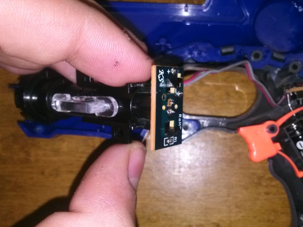
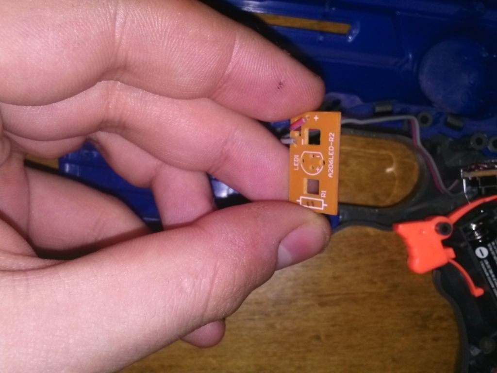
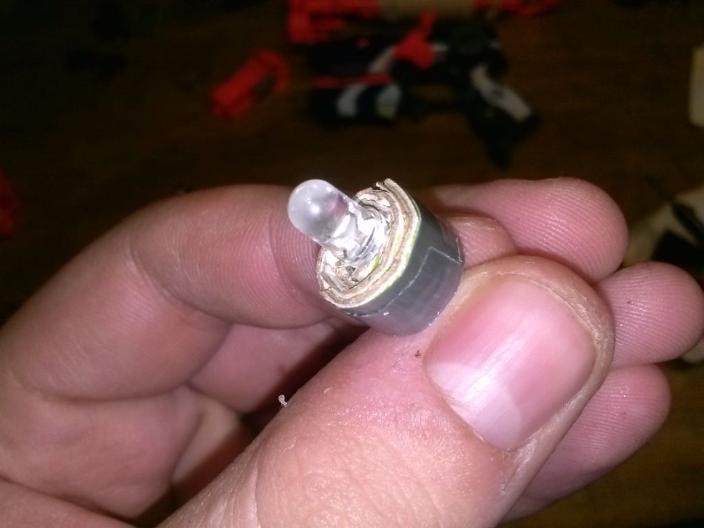
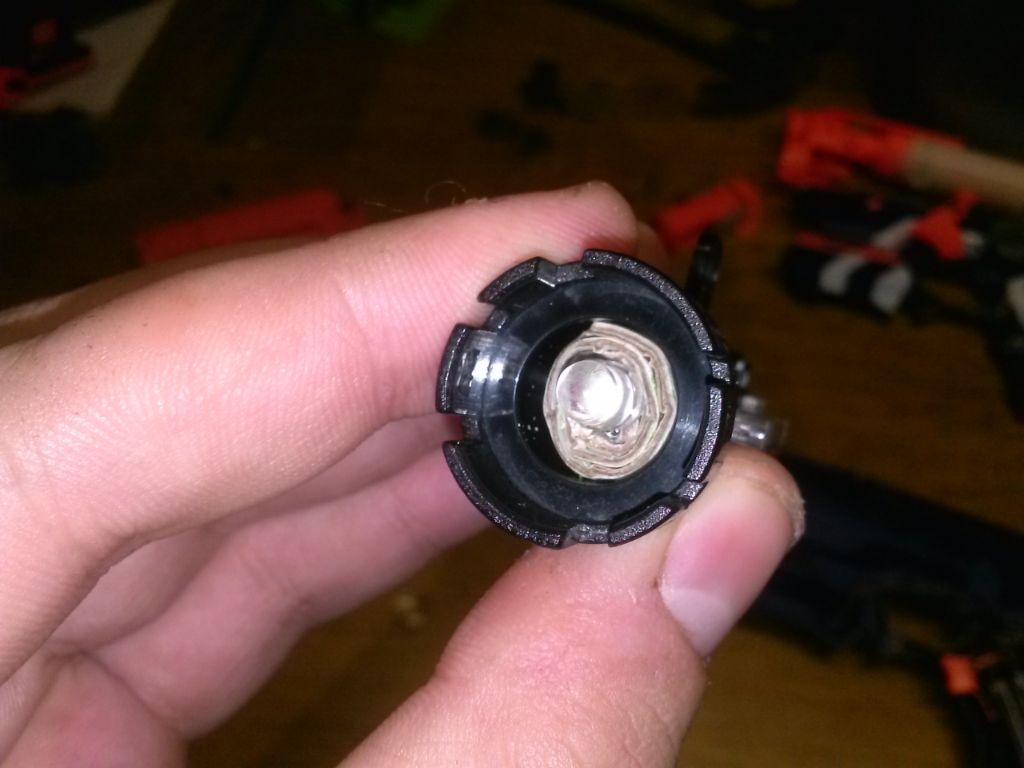
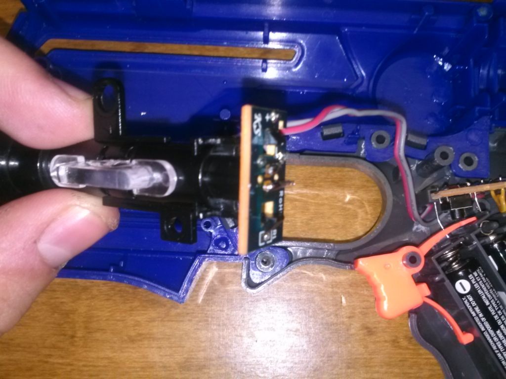
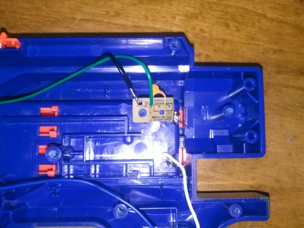
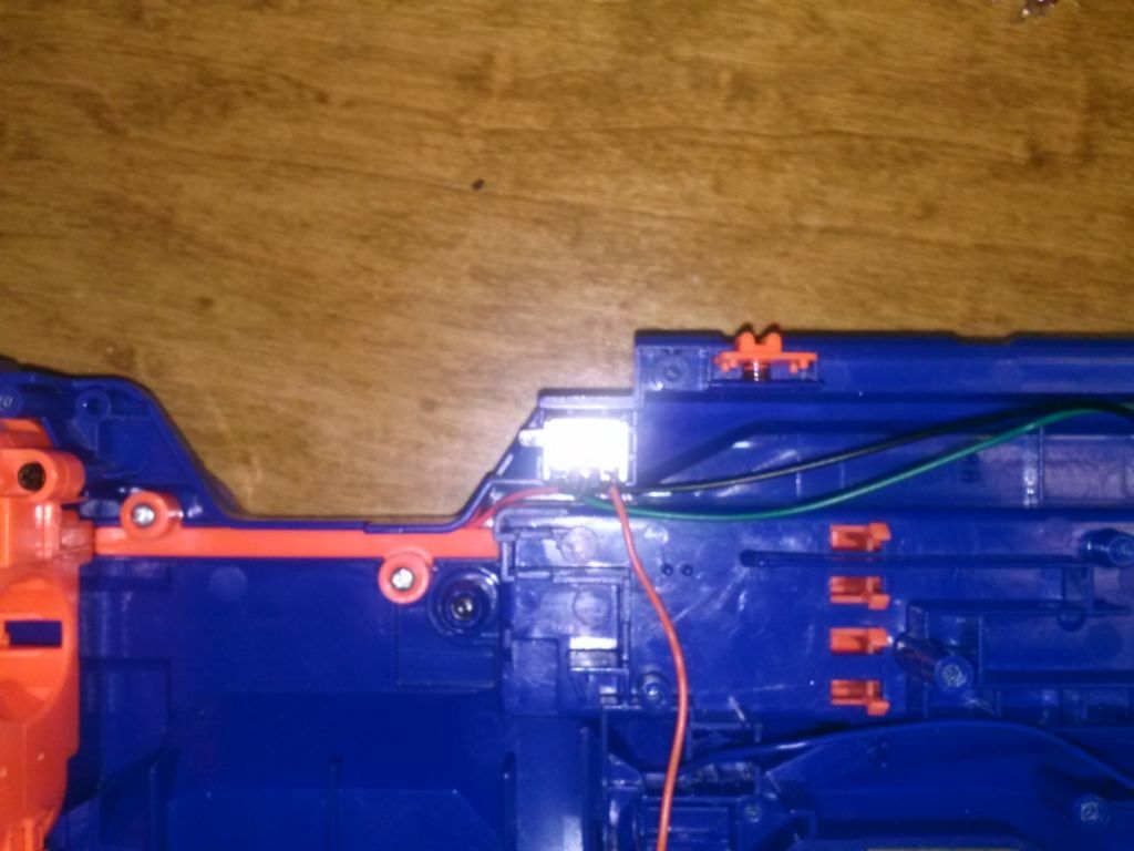
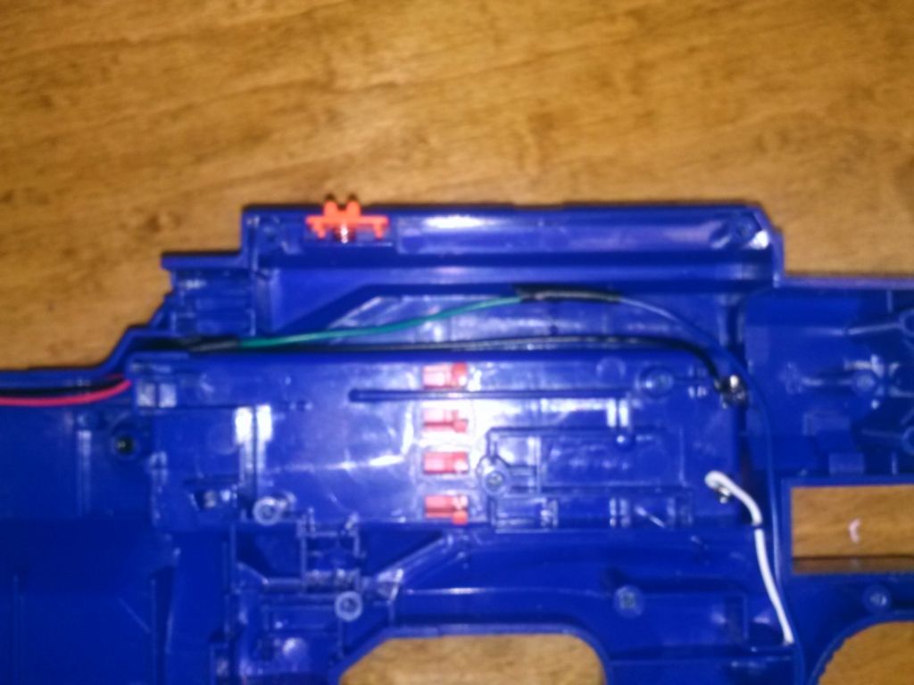
STEP 5 - REMOVING THE VOLTAGE RESISTOR (THERMISTOR?)
There is this little circuit board with a yellow resistor and two wires, green and black. Cut the black wire and the green wire from the board. Then cut the resistor from the battery terminal. You should now have the circuit board with only the resistor on it.
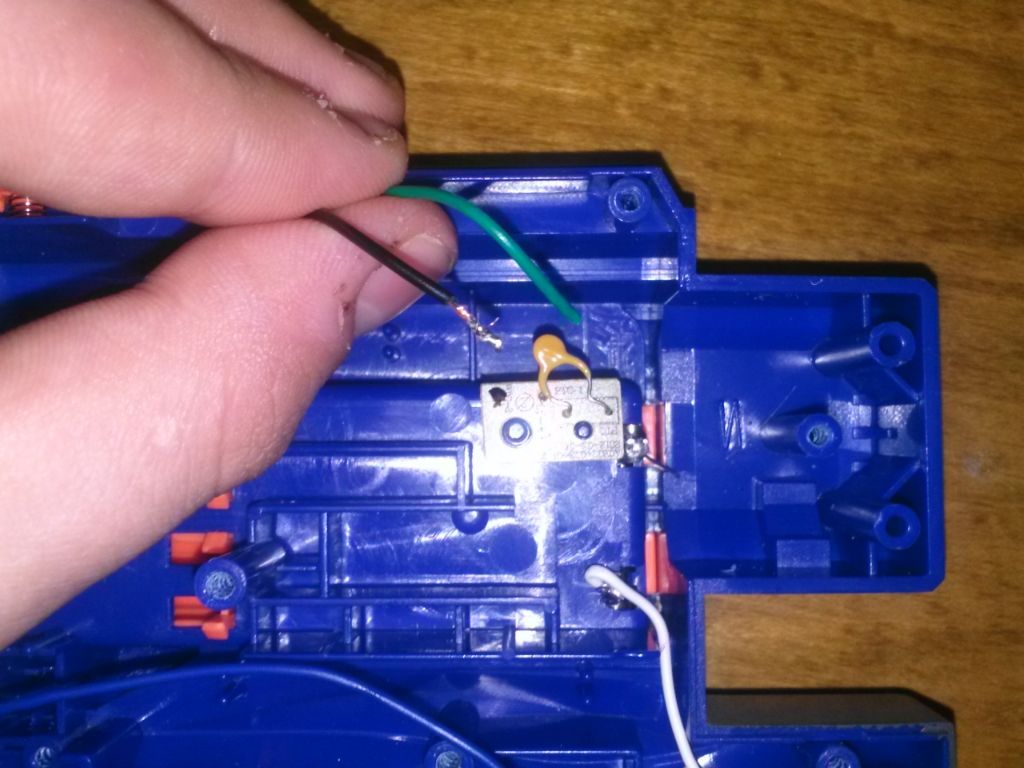
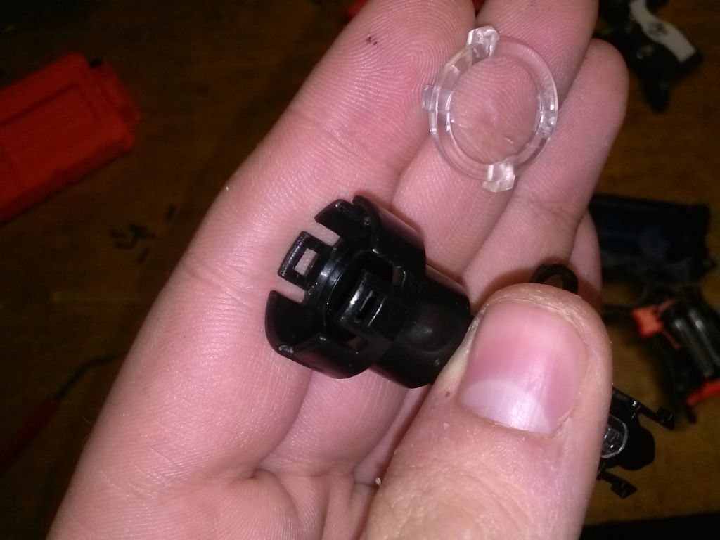
STEP 6 - REMOVING THE JAM DOOR LOCK
This button has three wires going to it - Orange, red, and green. Cut them all from the button. You should now have a free orange wire, a free green wire, and a button. Put them to the side. Save the wire, you might need it later.
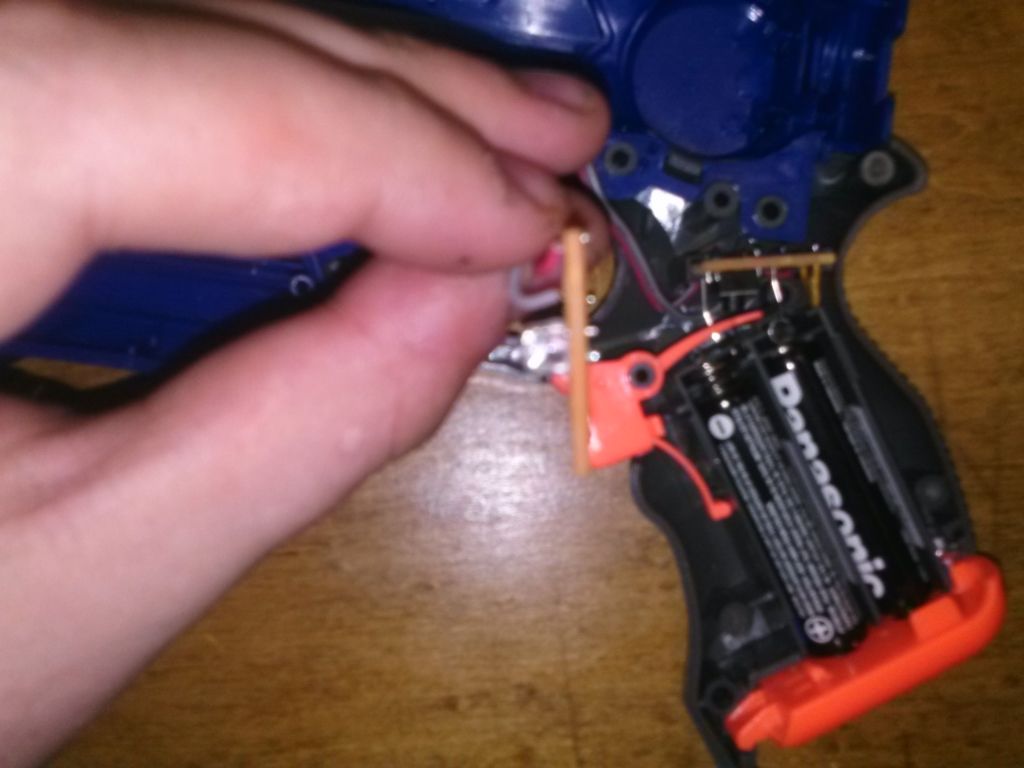
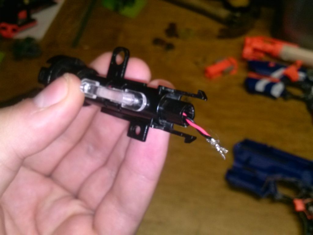
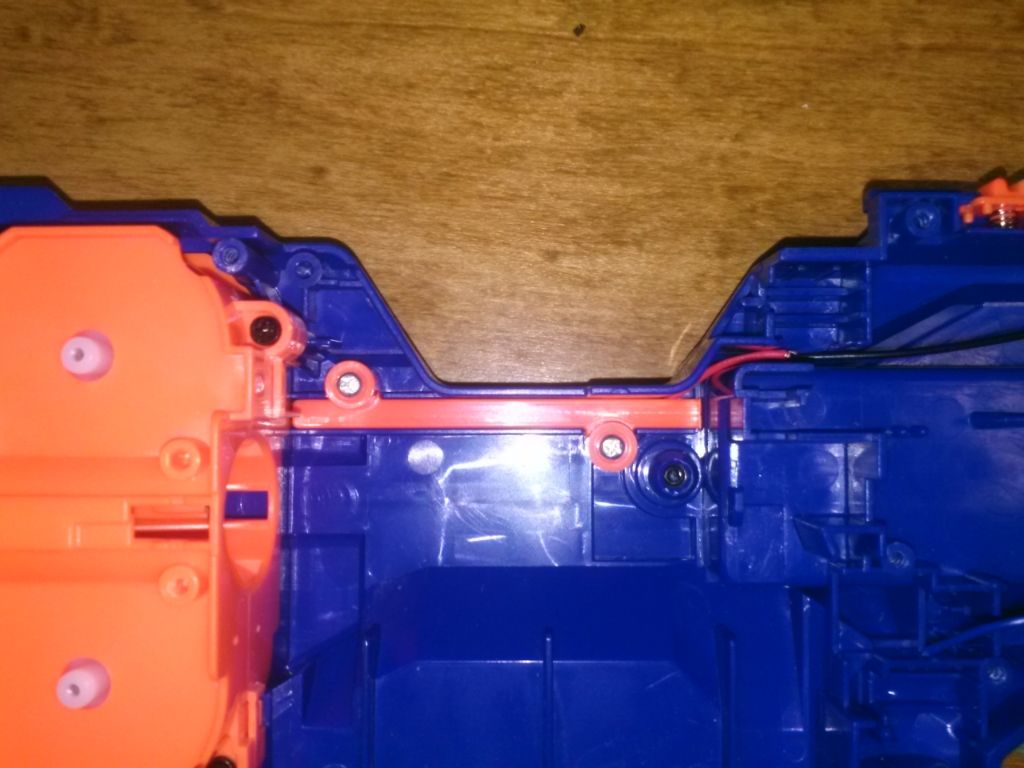
STEP 7 - FREEING UP THE RED WIRE
To get to the red wire easier, you can unscrew this orange piece. It just covers the wires coming from the motors. Removing the orange plate allows you to move the wires and work with them easier.
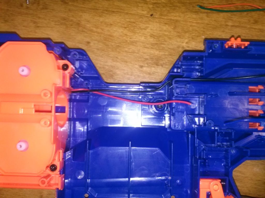
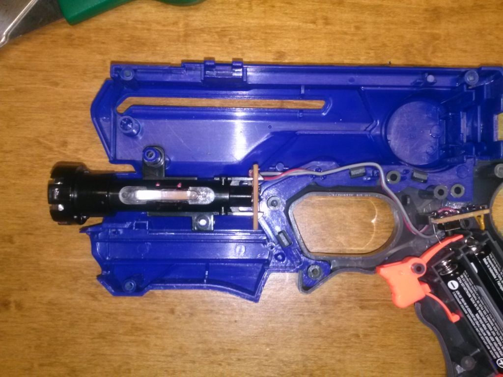
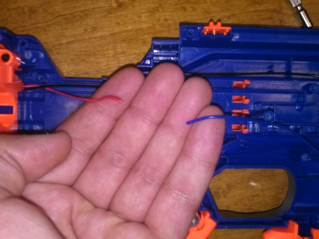
STEP 8 - STEP BACK A MINUTE
Ok, let's take a quick break and see what we've got. We should have a blue, red, and black wire not connected to anything. The blue wire coming from the motor button, and the red and black wires coming from the motors.
STEP 9 - STEP BACK A MINUTE PART 2
You should have the following free pieces: A green wire, a orange wire, two buttons, and the circuit board with the voltage resistor on it.
STEP 10 - TIME TO CONNECT THE WIRES
Take the black wire and solder is to the negative (Top) battery terminal.
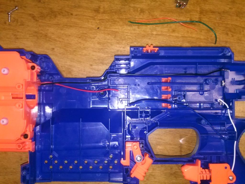
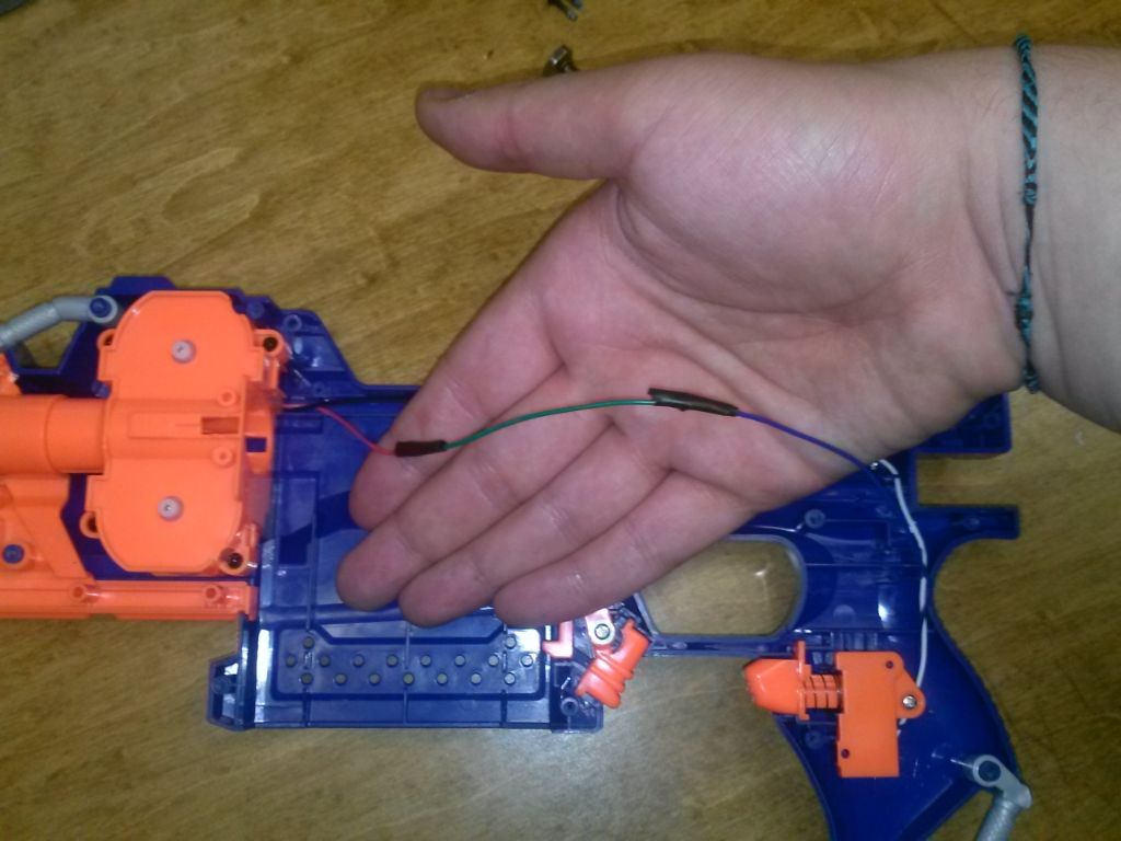
STEP 11 - TIME TO CONNECT THE WIRES PART 2
Now we need to complete the circuit by connecting the red wire from the motors to the blue wire from the motor button. You can see if they are long enough to solder right together, but I had to put the green wire between them to make it long enough to fit around some internals. This is why I said to save the wire you cut out.
STEP 12 - MAKING STUFF FIT
Take the newly connnected wires and route them above the battery compartment. This is why you might need to add some wire - Just soldering the blue to the red may not be long enough to go around here.
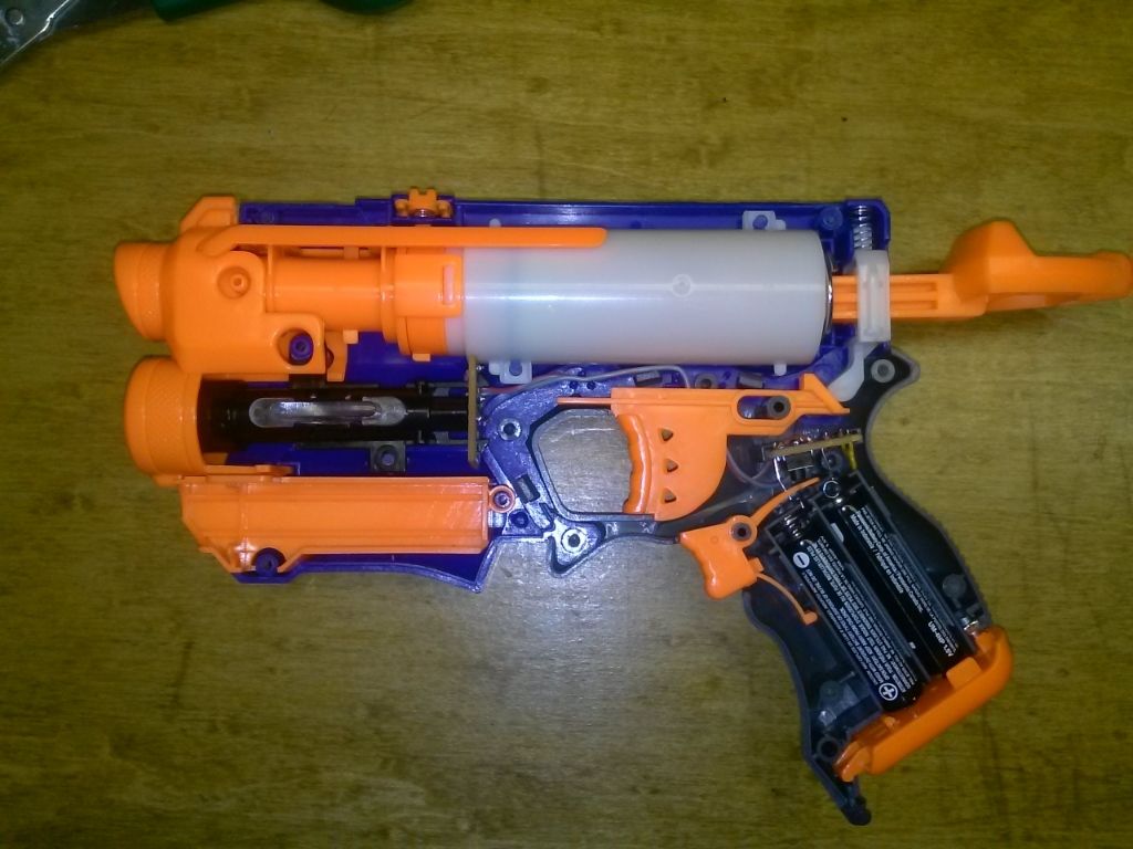
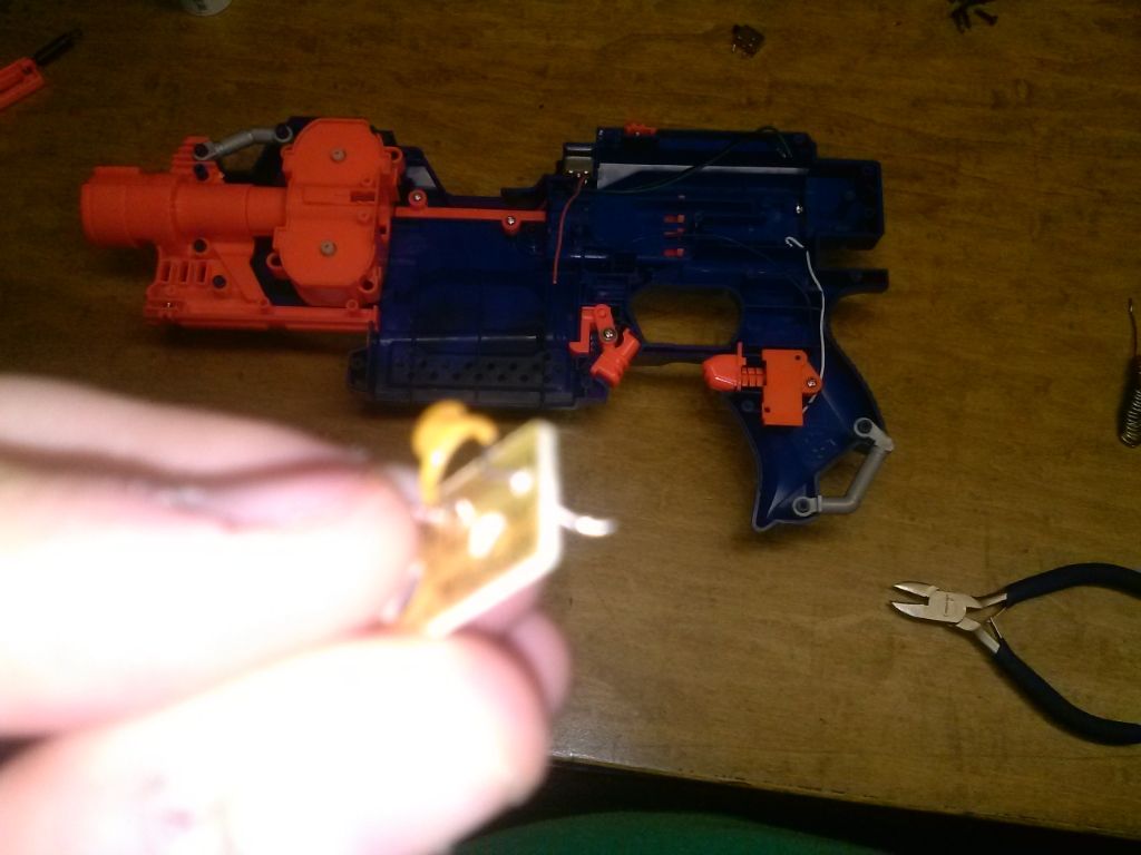
STEP 13 - PUT STUFF BACK
Replace the trigger and then the dart pusher. Put the spring back over the peg in the back.
AND YOU'RE DONE!!!
There you go. The final product should look like the above image in step 13. Remember, I took out some mechanical locks too (One in the magwell by the button we took out, one above the motor button, and one in front of the dart pusher), so mine may look just a little different in those ways. Any questions, comments, or feedback is welcome. This is my second tutorial, so I hope everything is good.
Happy modding,
SoftButFirm