Jump to content


Photo

Different Wiring For Two Stage+ Flywheel Builds

Flywheel Two Stage Wiring

5 replies to this topic

#1 Quack

Quack

    Member

  • Members
  • 75 posts

Posted 28 November 2017 - 10:09 PM

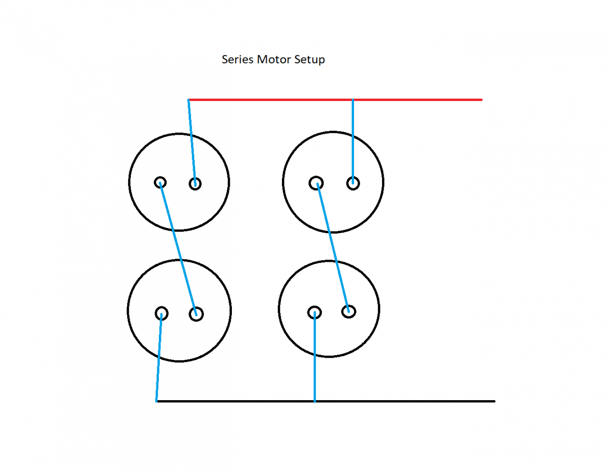
So I was in English Class today thinking about Nerf mods as usual when I came across an interesting solution I have been having with two stage flywheel builds. In a typical single stage build the motors are wired in parallel so that the entire voltage of the battery drops across each motor causing them to spin at their max rpm for the given voltage of the battery. However this means that the maximum current drawn by the motors in this setup is the sum of their stall currents. In a single stage setup this will top out at ~50A for the thirstiest motors and shouldn't be that much of a problem for a typical 3s battery. However in a two stage or more build with 4+ motors being used, this current draw could be over 100A! Not only is this much more than many 3s batteries are rated for, but it is incredibly dangerous. However, by rethinking the motor wiring, I think this issue can be solved. By wiring each set of motors in series and them those sets in parallel, the amount of current drawn is halved. On the flip side, double of the amount of voltage is required to spin the motors to the same RPM. I have been doing some searching and found this 6s battery which I think should be able to accomplish the job and isn't too much more expensive than a 3s. I have some diagrams below showing the difference in wiring. I'd like to know what you guys think since I'm only 85% positive on my physics. 

paralell 2 stage.png

series 2 stage.png


Edited by Quack, 28 November 2017 - 10:09 PM.

  • 0
When I get excited I eat rocks.

#2 meow121325

meow121325

    Member

  • Members
  • 125 posts

Posted 29 November 2017 - 03:18 PM

your theory is sound and may only need a few tweaks depending on the blaster your using you my friend will make nerf modding history!


  • 0

#3 Meaker VI

Meaker VI

    Member

  • Moderators
  • 1,192 posts

Posted 29 November 2017 - 04:37 PM

I feel like the second one is showing motors in series, sets in parallel - both pairs of motors have wires leading to/from home, but the motors themselves only have 1 path. Your idea seems sound in my not-an-engineer head; just need to make sure the diagram is correct.


  • 0

#4 Quack

Quack

    Member

  • Members
  • 75 posts

Posted 29 November 2017 - 04:43 PM

I feel like the second one is showing motors in series, sets in parallel - both pairs of motors have wires leading to/from home, but the motors themselves only have 1 path. Your idea seems sound in my not-an-engineer head; just need to make sure the diagram is correct.

Yeah the diagrams are correct. Or at least they are what I intended. The two stages are in parallel while the motors within each stage are in series.


  • 0
When I get excited I eat rocks.

#5 Remzak

Remzak

    Member

  • Members
  • 94 posts

Posted 09 December 2017 - 05:02 PM

Yeah the diagrams are correct. Or at least they are what I intended. The two stages are in parallel while the motors within each stage are in series.

Since the two stages are in parallel though I don't think it makes a difference. You got me thinking, and I just threw together a quick rig to check and see if the idea had any merit. I rigged two motors to my bench power supply, once with them in series, and once with them in parallel. Your physics is correct, the pair in series pulled 0.22A at 7.4V fixed and with no load, while in parallel they pulled 0.56A at the same voltage. The motors in series were audibly spinning much slower than those in parallel.

I then doubled the voltage supplied to the motors in series, and at 14.8V fixed they pulled 0.31A, a bit more than half the current of the parallel system, at a very (audibly at least) similar rpm. I believe your theory is correct, while impractical.

The issue is that all we do is redirect the problem. Watts=Volts*Amps and so instead of choosing a bigger 3 Cell battery that could handle the amperage you recommend picking a bigger six cell battery that diverts the problem. Minimizing amperage is definitely benificial, but seems unnecessary and impractical for our use.
  • 0
Unnoficial "Drone" Expert

#6 Quack

Quack

    Member

  • Members
  • 75 posts

Posted 09 December 2017 - 05:53 PM

The issue is that all we do is redirect the problem. Watts=Volts*Amps and so instead of choosing a bigger 3 Cell battery that could handle the amperage you recommend picking a bigger six cell battery that diverts the problem. Minimizing amperage is definitely benificial, but seems unnecessary and impractical for our use.


I see what you're saying and I get that it really only redirects the problem, but I think I'm going to try it on my latest build more out of necessity than convenience. I designed and 3d printed my own 2 stage cage for the stryfe and put hellcats as the first stage and wolverines as the second (all on a 3s). When I first tested it in a completely parallel setup I melted the inside of my high amp switch. I originally estimated that the wolverines would draw 30 to 40 amps at 3s but when I finally found a data sheet I saw that they draw 70 amps each. All totaled my setup draws 184 amps which is way more than any switch small enough for the blaster could handle. I just ordered the 6s I linked in my first post and will do a write up if it works. Obviously I would avoid this setup in the future, but I don't want to just abandon this project.


  • 0
When I get excited I eat rocks.


Also tagged with one or more of these keywords: Flywheel, Two Stage, Wiring

0 user(s) are reading this topic

0 members, 0 guests, 0 anonymous users