Jump to content


Photo

Rapidstrike FCG Microswitch Bracket

rapidstrike fire control group bracket

13 replies to this topic

#1 CaptainSlug

CaptainSlug

    Resident Mad Scientist

  • Administrators
  • 4,763 posts

Posted 29 December 2016 - 04:46 PM

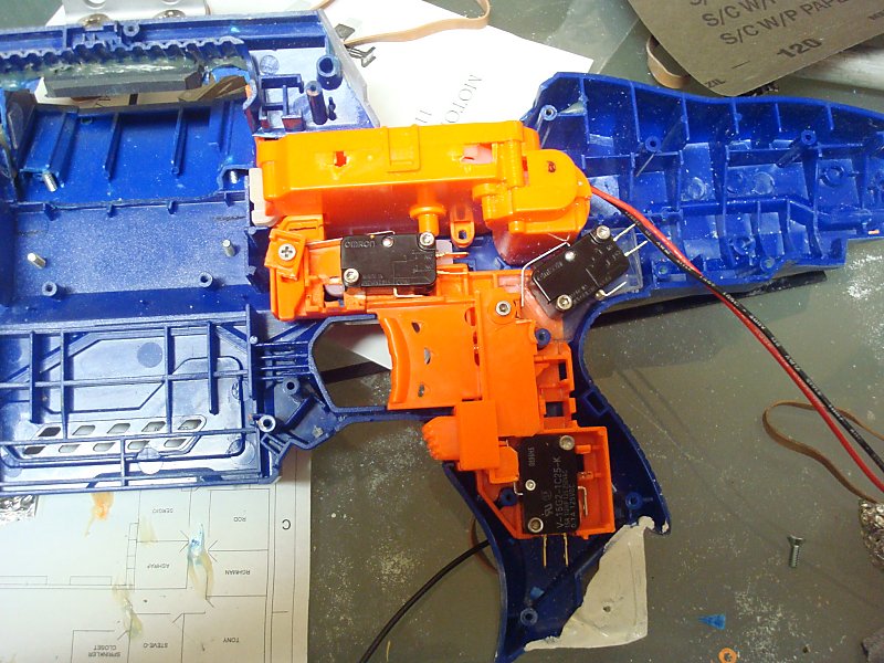
This is probably a little bit of overkill since it's usually only the flywheel switch that needs to be replaced. But I just did not like the tactical sensation of the stock switches so I wanted to see if I could use nothing but microswitches.


I'm using Mcmaster part# 7510T12 for the flywheel switch, and 7779K63 for the other two.

ps_16.jpg

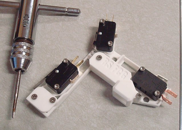
This took a fair amount of fiddling to get just right. And now that I have it finished I went ahead and modeled it so others can 3D print their own.

And if you want to do so, the following needs to be done to duplicate the result shown above.


  • The trigger switch lever needs to be bent around the end of the switch.
  • The flywheel switch lever needs to be clipped shorter or removed completely by drilling out the rivet.
  • The stock plastic piece for the park switch for the pusher needs to have the spring peg clipped off of it. You will still be able to use the spring if you want.
  • The holes for the switches will need to be drilled and tapped for UNC 4-40 screws, as will the standoffs for the two cover plates.
  • Use wire cutters to snip off the first rib of plastic below the pusher motor to make room for the trigger switch


rs_fcg.jpg

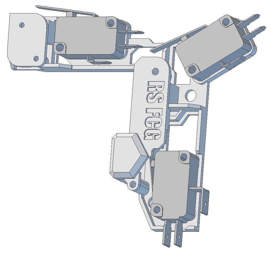
The screw holes that allow you to attach the plate inside the shell are countersunk, so you can use flat head 4-40 screws to install the plate. Then simply attach all the micro switches to the plate using 3/4" length 4-40 screws.


https://www.shapeway...oduct/KDWZQDA3N


STL File


http://captainslug.com/nerf/rs_fcg.zip


Solidworks Assembly


http://captainslug.c.../rs_fcg_sld.zip


I will be ordering one of these prints and putting it in my other Rapidstrike once it arrives.


Edited by CaptainSlug, 16 January 2017 - 12:13 PM.
Added submicro switch compatibility

  • 0
The little critters of nature, they don't know that they're ugly. That's very funny, a fly marrying a bumble bee. I told you I'd shoot, but you didn't believe me. Why didn't you believe me?

#2 Zack the Mack

Zack the Mack

    Member

  • Members
  • 360 posts

Posted 29 December 2016 - 04:56 PM

This is rad. I wish I had access to this when I was still modding my Rapidstrike.


When I make another Rapidstrike, I'll model custom triggers so you don't need to modify the microswitches.


tactical sensation

I see what you did there


  • 0
Ask me questions about electronics, Arduino, and 3D printing

#3 CaptainSlug

CaptainSlug

    Resident Mad Scientist

  • Administrators
  • 4,763 posts

Posted 29 December 2016 - 05:03 PM

Bending the lever arm is a piece of cake. You just close the switch, then roll the lever around the corner of the housing.


The lower flywheel switch simply needs the arm clipped with wire cutters or a dremel as it's too long and doesn't really get used by the switching action.


I just made some slight tweaks to the model and reuploaded them.


  • 0
The little critters of nature, they don't know that they're ugly. That's very funny, a fly marrying a bumble bee. I told you I'd shoot, but you didn't believe me. Why didn't you believe me?

#4 Trashmouse

Trashmouse

    Member

  • Members
  • 26 posts

Posted 29 December 2016 - 05:37 PM

This looks really cool! but is there any real advantage to use this instead of the usual switch replacements?


  • 0

#5 blitz

blitz

    Member

  • Members
  • 285 posts

Posted 29 December 2016 - 05:59 PM

This is nice, will definitely be putting this in my RS when I mod it this semester. May want to put this on reddit as well. 


Why did you use different switches for the rev trigger and pusher mechanisms?


  • 0
Blitz, member of the FNBS
"sexual innuendo no intendo"

#6 CaptainSlug

CaptainSlug

    Resident Mad Scientist

  • Administrators
  • 4,763 posts

Posted 29 December 2016 - 06:49 PM

Here's how I intend to wire this rapidstrike.

rs_fcg_circuit.gif

Though the same circuit could be done without the relay so long as the expected stall current draw for all three motors together is below 25 amps.

http://captainslug.c...cg_circuit2.gif


This looks really cool! but is there any real advantage to use this instead of the usual switch replacements?

The "Usual" is to just replace the flywheel switch, which you can fairly easily do with the stock fcg. Though some people use sub-micro switches for the two pusher switches. But the bracket models for doing that aren't publicly available. I'll update mine to accept both tomorrow.
 

Why did you use different switches for the rev trigger and pusher mechanisms?

The pusher circuit doesn't require the higher current rating that the flywheel circuit needs, and the 15amp switches are cheaper ($2.75ea instead of $5.69ea)


Edited by CaptainSlug, 30 December 2016 - 11:16 AM.

  • 0
The little critters of nature, they don't know that they're ugly. That's very funny, a fly marrying a bumble bee. I told you I'd shoot, but you didn't believe me. Why didn't you believe me?

#7 shardbearer

shardbearer

    Member

  • Members
  • 177 posts

Posted 31 December 2016 - 01:09 AM

Very nice! Printing a copy now.

Edit: Looks like you need support material for this?


Edited by shardbearer, 31 December 2016 - 01:14 AM.

  • 0

#8 CaptainSlug

CaptainSlug

    Resident Mad Scientist

  • Administrators
  • 4,763 posts

Posted 06 January 2017 - 01:44 PM

Prototype set came from shapeways today. Had to trim some material off near the trigger switch, and the 5mm holes had to be drilled out. I've updated the models in the first post and the shapeways product page to correct for these tolerances. I've already confirmed that the stock trigger, rev switch, and park switch parts fit.

rs_fcg2.jpg

I also discovered that the lever on the 25 AMP switches can be removed if you pry the case open a just enough to pull it out. This saves the hassle of having to trim it to length, and the stock rev switch button can just interact with the button directly now.


I will probably have a photo of one of these installed in a blaster by the end of this weekend.


Edit: Looks like you need support material for this?

There's a little bump on the backside of the main plate that provides a well for the rev switch. The part would probably work with that well shaved off if you want to print without support material.


  • 0
The little critters of nature, they don't know that they're ugly. That's very funny, a fly marrying a bumble bee. I told you I'd shoot, but you didn't believe me. Why didn't you believe me?

#9 shardbearer

shardbearer

    Member

  • Members
  • 177 posts

Posted 07 January 2017 - 09:16 PM

Oh I see, this was meant for SLS printing. I split the STL into the three parts, then rearranged the parts to be flatter on a print bed. Removing the nubs on the bottom seems like it would mess with the function too much. Files on Thingiverse here.


  • 0

#10 Kid Flash

Kid Flash

    Member

  • Members
  • 1,985 posts

Posted 19 January 2017 - 04:02 AM

I just printed one of these, and really wish I was better at understanding it...  I've always wired rapidstrikes with 2 switches, following "Make Test Battle"'s guide.  Is there something gained with this 3rd switch?  I also wish I was better at 3D modeling as I'd like to draw one of these for just the 2 switch design.  haha.  I've been out of here for a while, but when I left you had taken off Slug, good to see that you're back in the hobby.  Looks like I'll run to the hardware store tomorrow for some 4-40 screws.


  • 0

#11 jaxmeh

jaxmeh

    Member

  • Members
  • 40 posts

Posted 19 January 2017 - 07:27 AM

The third switch allows for better cycle control. Your pusher will never stop half-extended or half-retracted like it does with a two-switch scheme if you're not careful. Two switches are fine for noobs or if you just want to dump mags, but if you want single shots or three round bursts without jams, then use a three switch setup with cycle control. Check out torukmakto4's blog for some better Rapidstrike wiring guides. Follow his standard Rapidstrike guide for something that will give you an idea of the advantages of a 3 switch build without having to build custom FCGs like this.

Edited by jaxmeh, 19 January 2017 - 07:29 AM.

  • 0

#12 CaptainSlug

CaptainSlug

    Resident Mad Scientist

  • Administrators
  • 4,763 posts

Posted 19 January 2017 - 08:58 AM

 I'd like to draw one of these for just the 2 switch design. 

Just cut off the top/front half. Or don't bother mounting the third switch up there.

The third switch is important for providing a parked position for the pusher though.


  • 0
The little critters of nature, they don't know that they're ugly. That's very funny, a fly marrying a bumble bee. I told you I'd shoot, but you didn't believe me. Why didn't you believe me?

#13 Kid Flash

Kid Flash

    Member

  • Members
  • 1,985 posts

Posted 19 January 2017 - 11:08 AM

I can't say that the 2 switch method has ever given me any problems, but I'll give yours a try to see how it does. I'm all about simplicity, so less wires was a nice feature to me.
  • 0

#14 shardbearer

shardbearer

    Member

  • Members
  • 177 posts

Posted 21 January 2017 - 09:12 PM

I printed mine last week and just installed it. Fit was OK, needed several holes enlarged to fit over the screw posts and some ribs cut out of the shell. Two posts had to be cut off the left side of the shell, and both triggers would get stuck on the shell until I widened the trigger holes significantly. I think this was because the triggers were sitting about 1mm too far to the left side, but the bracket seemed to be all the way down. In live center mode, with a cheap ebay 180 motor that look like it doesn't have enough torque, the pusher was running away every time on 3S. On 2S, the cycle control was not good, often doing several pusher cycles after letting go of the trigger. Here's a video on Youtube demonstrating it. Moving the cycle control switch a few mm farther forward would probably help with this. On a dead center setup it was not good either, firing 5 or 6 shots with every short pull of the trigger, and I ended up going to a 2 switch setup. During its first war today, a friend tried to retract the stock and bent the tabs on the trigger switch together, causing it to the pusher to activate continuously, but I locked the stock and everything's working fine now. Though this is my first Rapidstrike, I feel it would probably be easier to do it the traditional way, without the printed bracket.

bW3hza8.jpg


  • 0


Also tagged with one or more of these keywords: rapidstrike, fire control group, bracket

1 user(s) are reading this topic

0 members, 1 guests, 0 anonymous users