Jump to content


Photo

Bullpup Variant Writeup

bullpup homemade writeup rainbow spring

14 replies to this topic

#1 Drev

Drev

    Member

  • Members
  • 135 posts

Posted 26 May 2014 - 08:21 PM

*
POPULAR

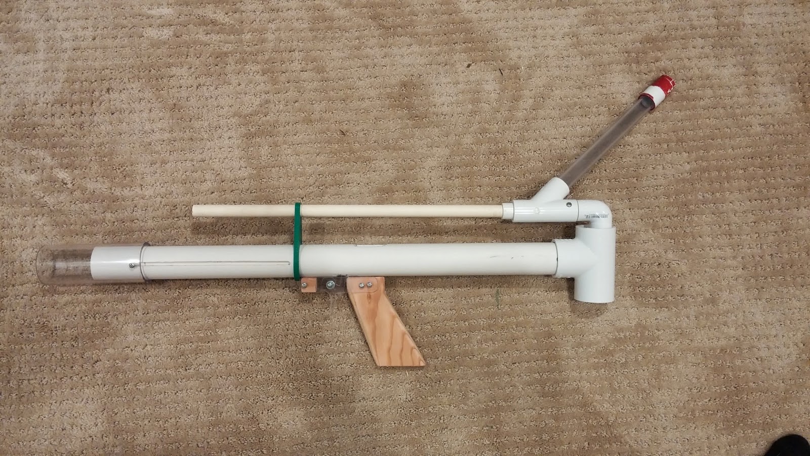
Here is the writeup for the bullpup. This blaster does take time to make, but if you have used a scroll saw and a dremel before, you will be fine. Since this blaster involves using those tools, it will be in the +bow category.

20140330_163301.jpg

Credit:
- The rainbow clan for inventing the rainbow catch
- Ryan201821 for the Rainbowpump and the handle templates
- Makeitgo for making the Multiple Orgasm

Tools:
- Screw Cutter/Mini Bolt Cutter
- Circle templates (little thin plastic thing with shapes to draw)
- A Dremel/Rotary Tool
- Sanding Drum
- Cutting disc
- A Scroll Saw
- A Drill
- 7/64, 5/32, and 11/64 bits
- A countersink bit
- 1/2" spade bit
- Tapping wrench
- 6-32 tapping bit
- A saw that can cut PVC
- Hobby Knife
- A ruler
- A yardstick/long architectural ruler
- Sand paper with sanding block
- Sanding Sponge
- Sharpie

Before I start the parts list, I highly recommend buying the 1" and 1.25" PVC from your local hardware store to cut down on shipping costs. However, you can find most of the parts you need at http://www.mcmaster.com/ . I will include the part numbers so you can easily find everything. For screws and other hardware, I am overestimating the amounts so you have extras. In order to find the screws and hardware on McMaster, just type in the info for the screw into the search bar.

- 8538K18: 1/2" nylon rod
- 9637k26: [k26] spring
- 4880k44: 1.25” PVC tee
- 4880K21: 1/2" PVC 90º elbow (2x)
- 48925K91: 1/2" PVC Pipe
- 48925K93: 1" PVC Pipe
- 48925K94: 1.25" PVC Pipe
- 4880k314: 1” to ½” PVC reducing bushing
- 9245k51: PETG tube 2” OD 1.75” ID buy 1'. OR buy 1.5" thinwall PVC.
- 2044T43: 1/2" ID PETG tube. This is the kind used for barrels.
- 8574k281: ¼” polycarbonate sheet 6”x6”
- 9691K56: U-Cup seal 7/8" ID 1-3/8" OD
- 91735A146: 6-32 3/8" panhead machine screws--You need about 20 if you don't buy 50
- 91735A151: 6-32 3/4" panhead machine screws--You need about 8
- 90126A007: #6 Zinc-plated washers

You will also need to purchase from a hardware store:
(Buy more than two of each screw)
- 6-32 1 1/4” machine screw (3x)
- 6-32 3/4" flathead machine screw (2x) OR thin 3/4" wood screws
- 6-32 locknut (1X)
- Silicone/White Lithium Grease
- Plumber's Goop
- 3/4" thick wood. It doesn't matter what kind, but make sure it isn't too soft. Poplar is great for this.

Not from hardware store of McMaster:
- Maverick/Nitefinder catch spring or any catch spring with a diameter similar to those. You can probably find a small spring similar to these in a hardware store though.

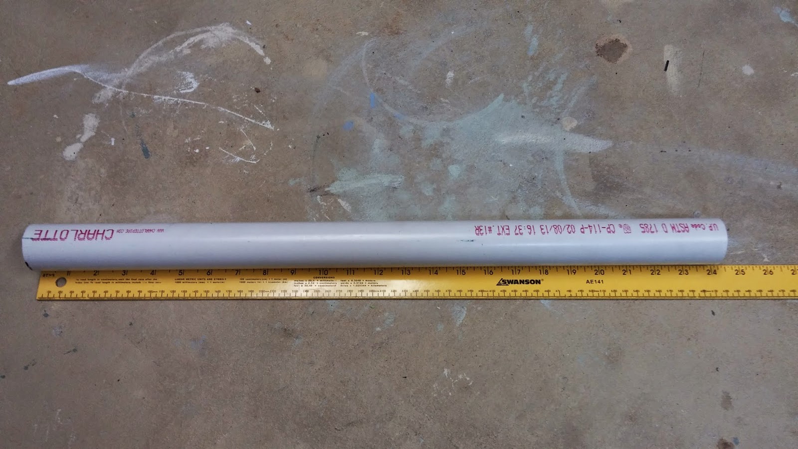
You're going to want to start off by cutting out a 24" length of 1.25" PVC. Use a hacksaw, dremel, or scroll saw to cut it nice and square.
20140325_111044.jpg


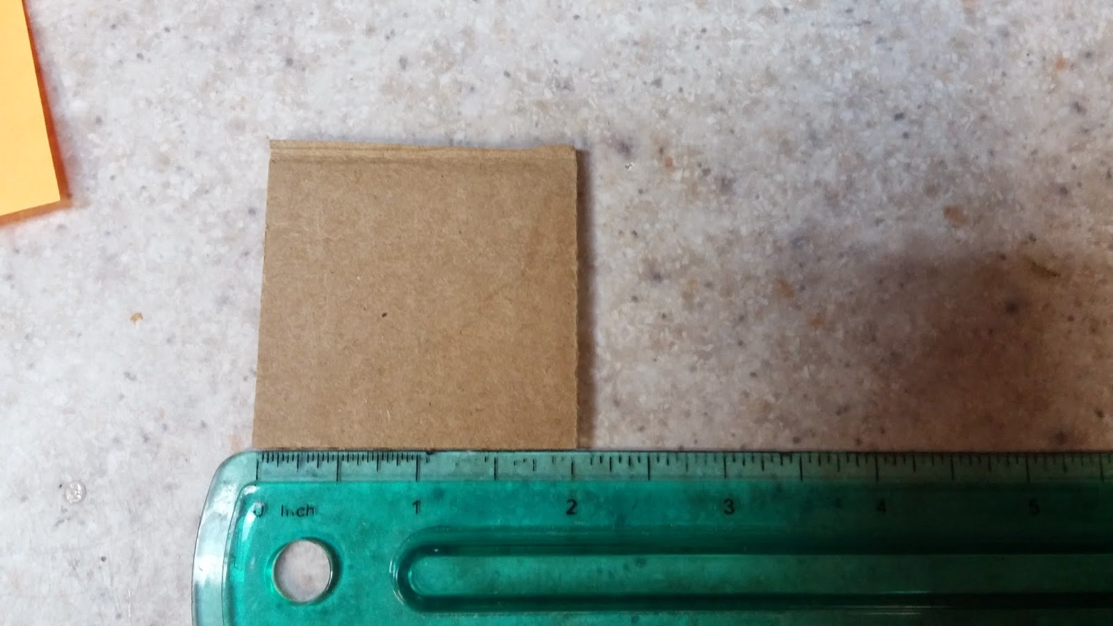
Next, make a simple quartering jig. This one is the most simple one out there. Cut out a 2" by 2" cardboard square.
20140325_110231.jpg

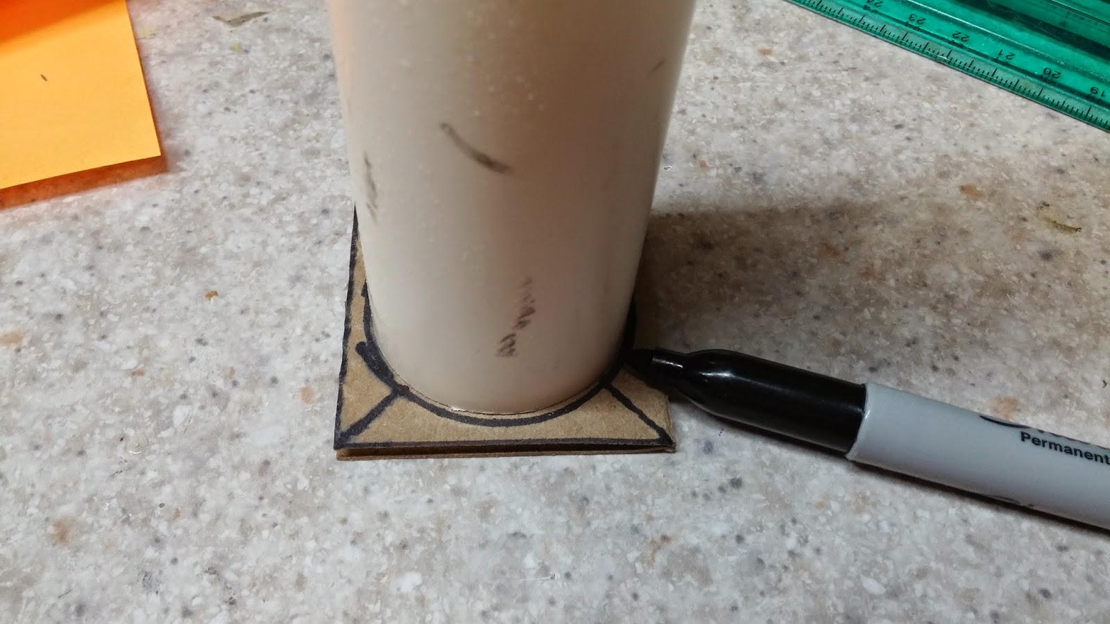
Try to place your PVC in the center and trace around it with your sharpie.
20140325_110341.jpg

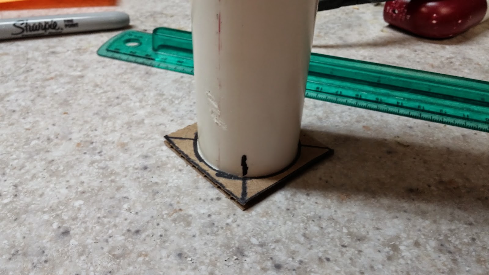
Line up the corners of the cardboard with the ruler and draw lines like this. Use the lines to make marks on your PVC.
20140325_110417.jpg
20140325_111202.jpg

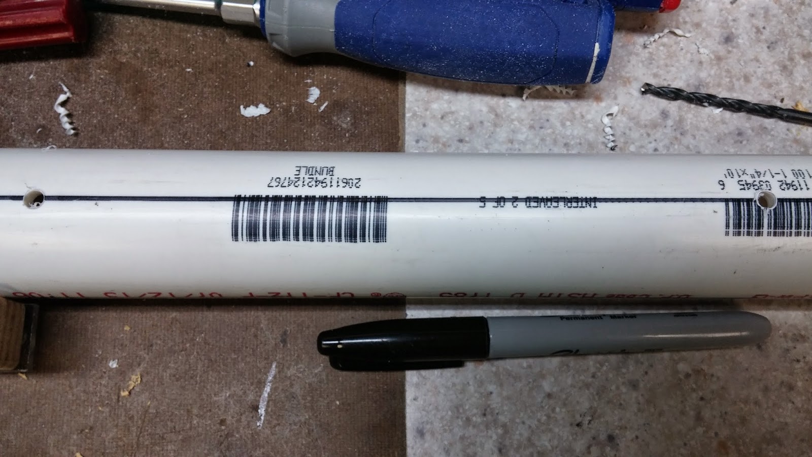
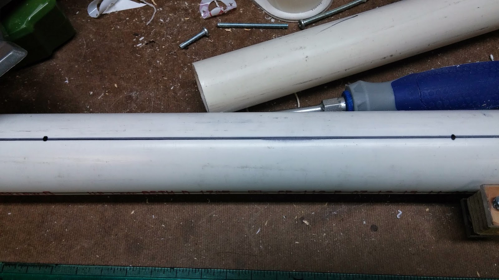
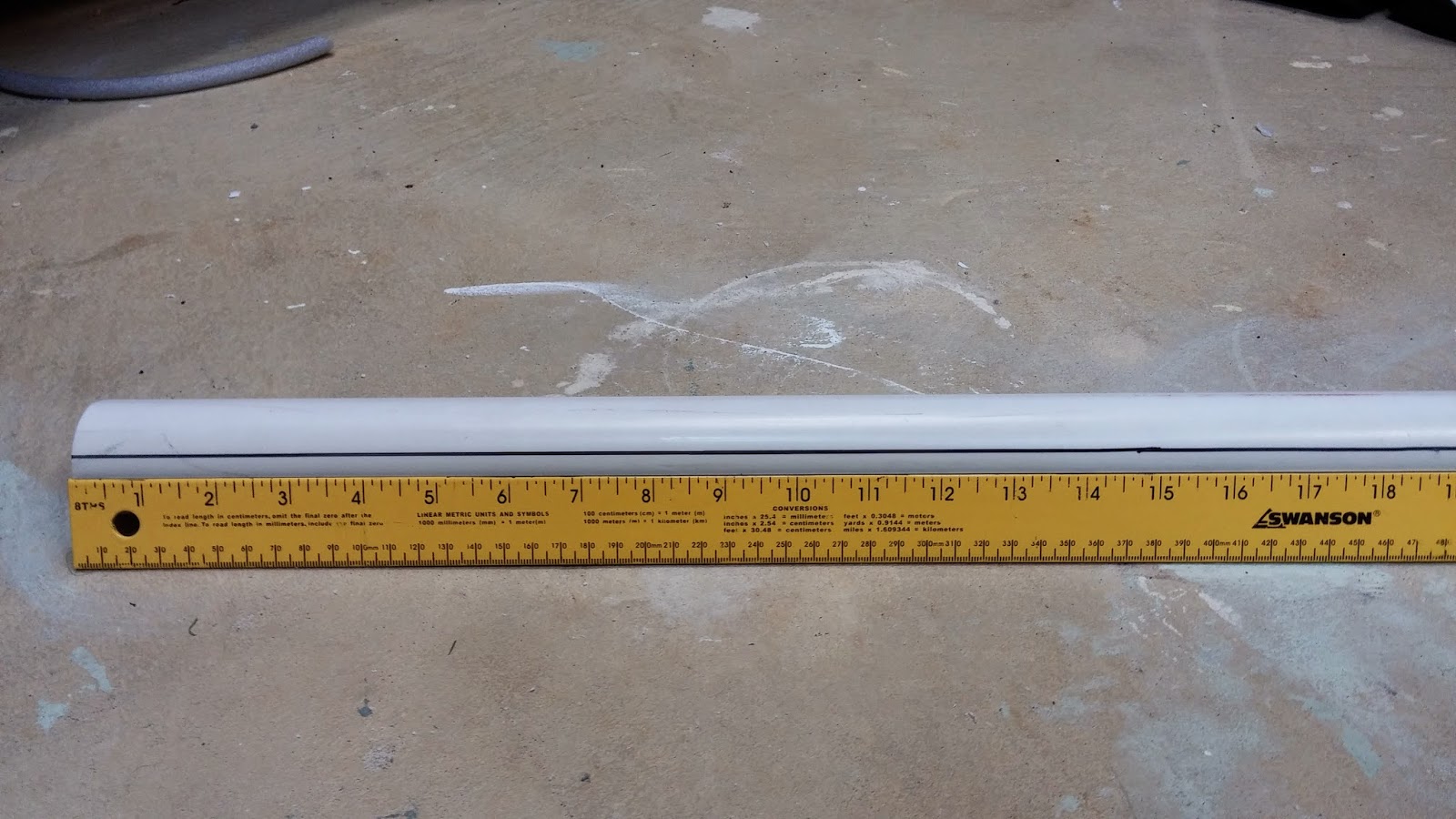
Use your ruler to draw four straight lines starting from the marks on the PVC to the other end.
20140325_111607.jpg

Now onto the bushing. You will notice that there is a part of the bushing that isn't the part that couples to the 1/2" PVC. Make a sharpie mark on this part of the bushing. Line up the bushing with the PVC like you are putting it in the pipe. Use the sharpie mark to make marks on each of the four lines of where you will be drilling the holes.
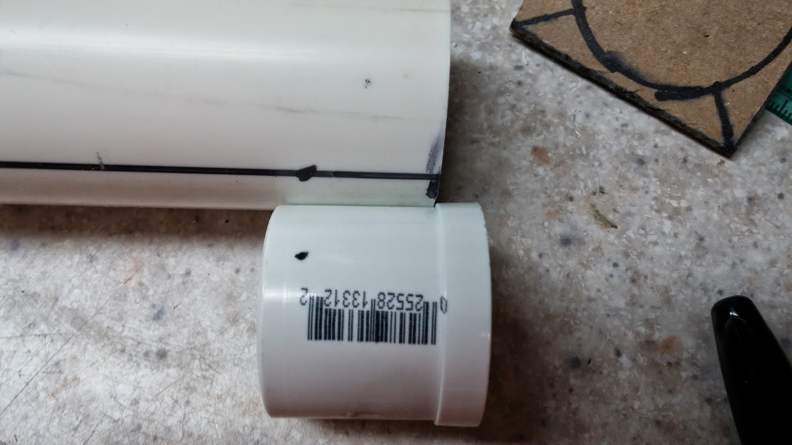
20140325_112050.jpg

Wrap packing tape around the bushing until it fits snugly into the PVC. You want an air-tight seal, but you also want to make sure you can still fit the bushing in. Once you have used the desired amount of tape, cut of the excess.
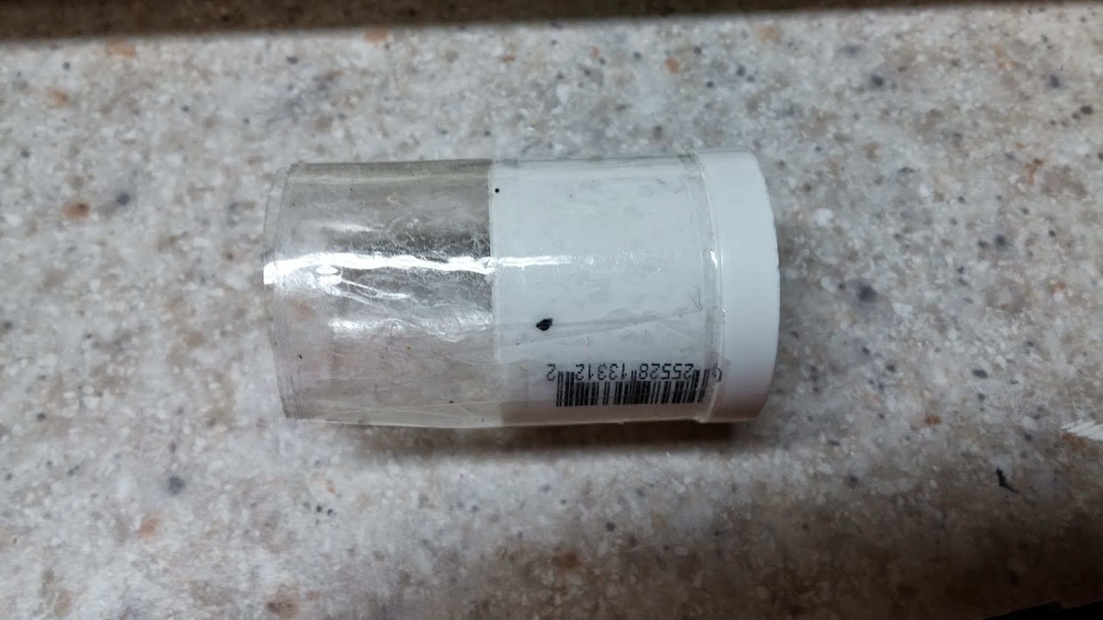
20140325_112741.jpg

Put goop around the bushing like so and put it in the PVC.
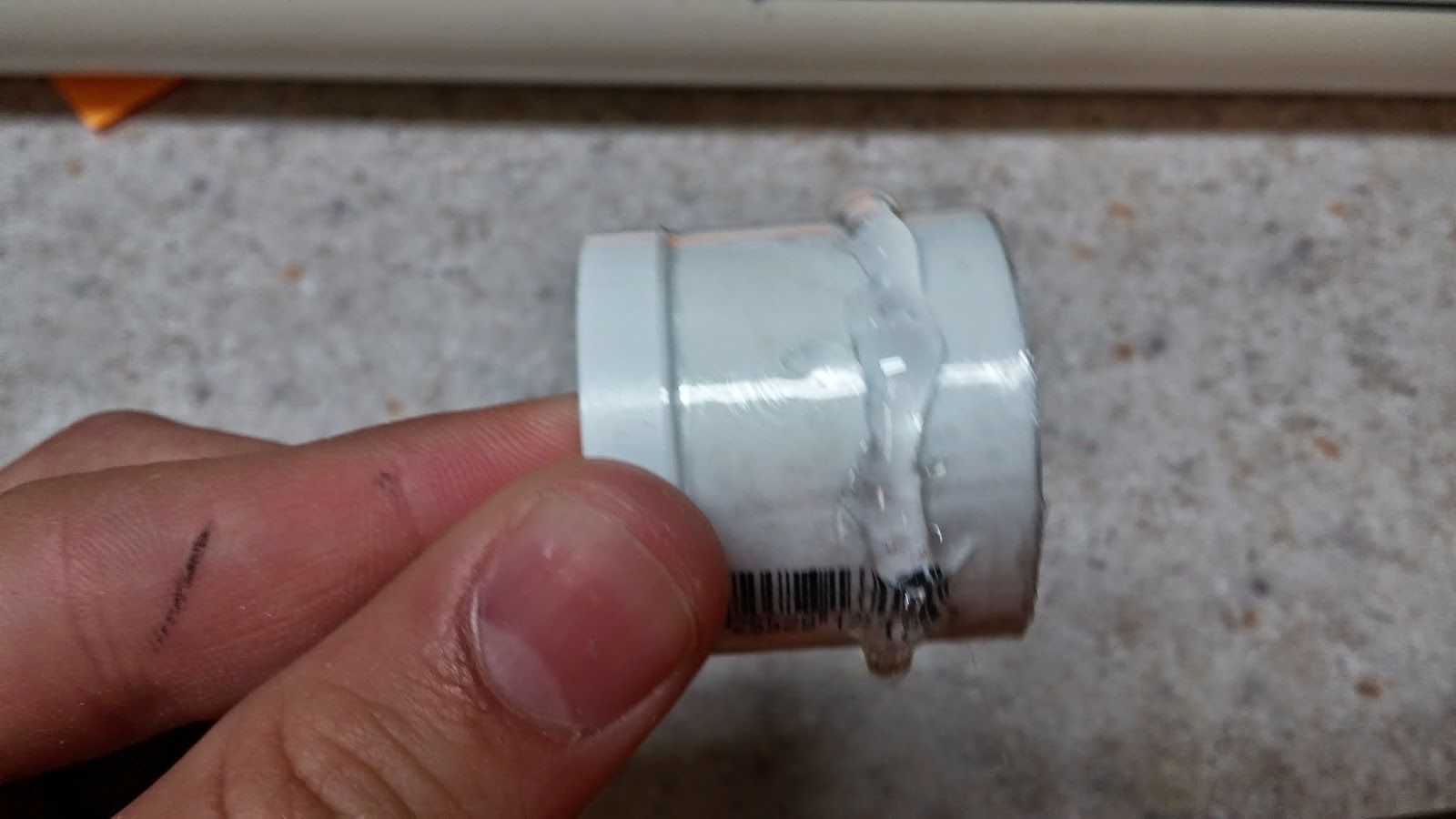
20140325_113005.jpg

Drill the holes where you made the marks and tap into the PVC with your 6-32 tapping bit. Use your countersinking bit on the holes and then screw the 6-32 3/8" panhead screws into the holes. If you did the tapping right, you shouldn't need to use more goop here.
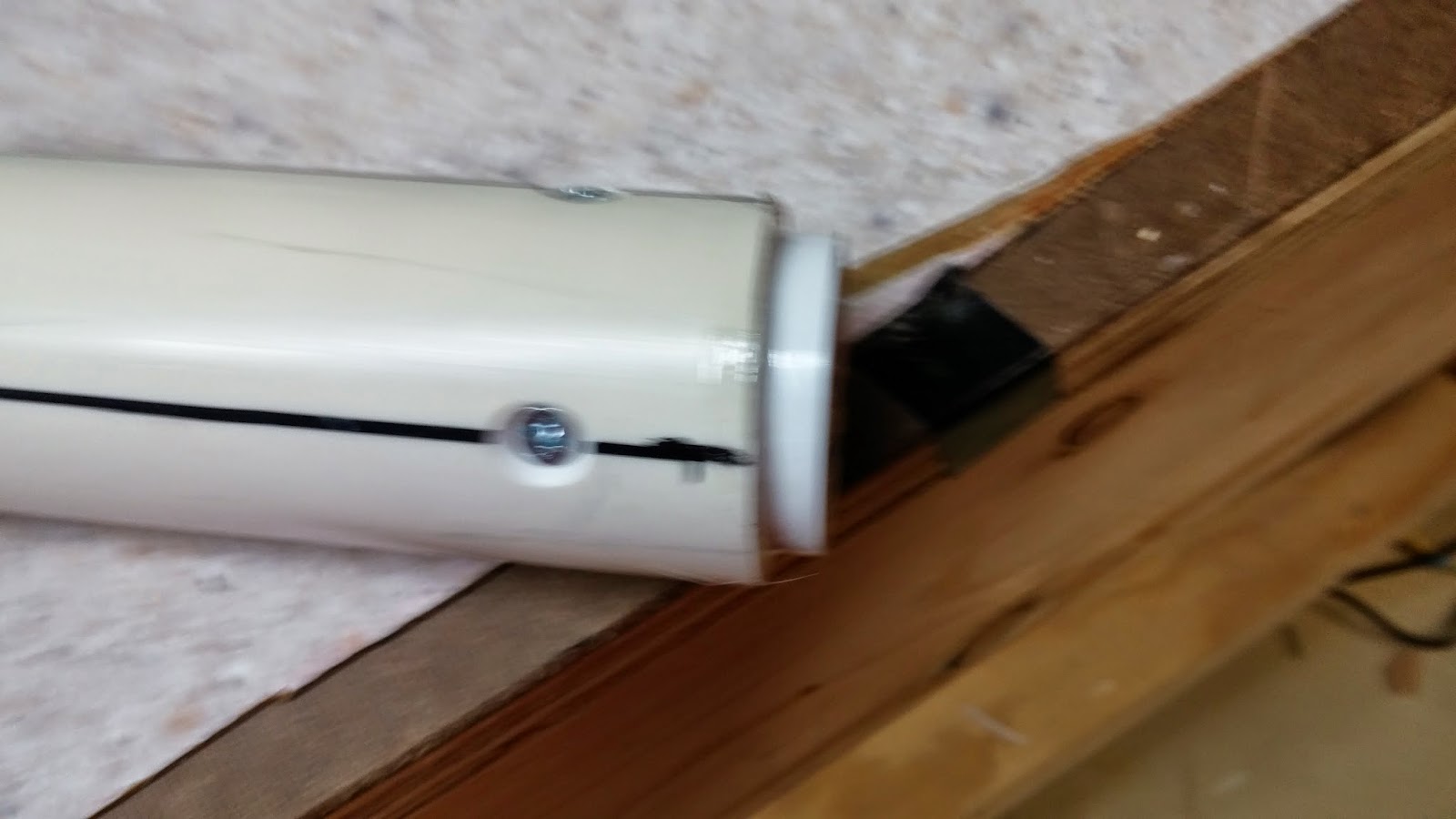
20140325_113615.jpg
20140325_114303.jpg

Set the pipe with the bushing away to dry. Meanwhile, you will be making the handle. Print out the templates made by Ryan201821. These templates can be found on his Rainbowpump writeup here. There are, however, many modifications to be made to these templates. I just used a pencil to do this.

First, extend the handle length by 2cm or 3/4" if you have a ruler without cm. Shorten the top of the handle by drawing a line 3/4" up from the small horizontal section. The picture explains it much better than I can. On the trigger guard (rectangle piece), draw a line to split it in half (2cm). On the trigger sideplates (big rectangle), draw a line 2cm in.
20140326_103648.jpg

Cut out the pieces and attach the handle and trigger guard to the 3/4" thick wood. Attach the handle sideplates to your polycarbonate.
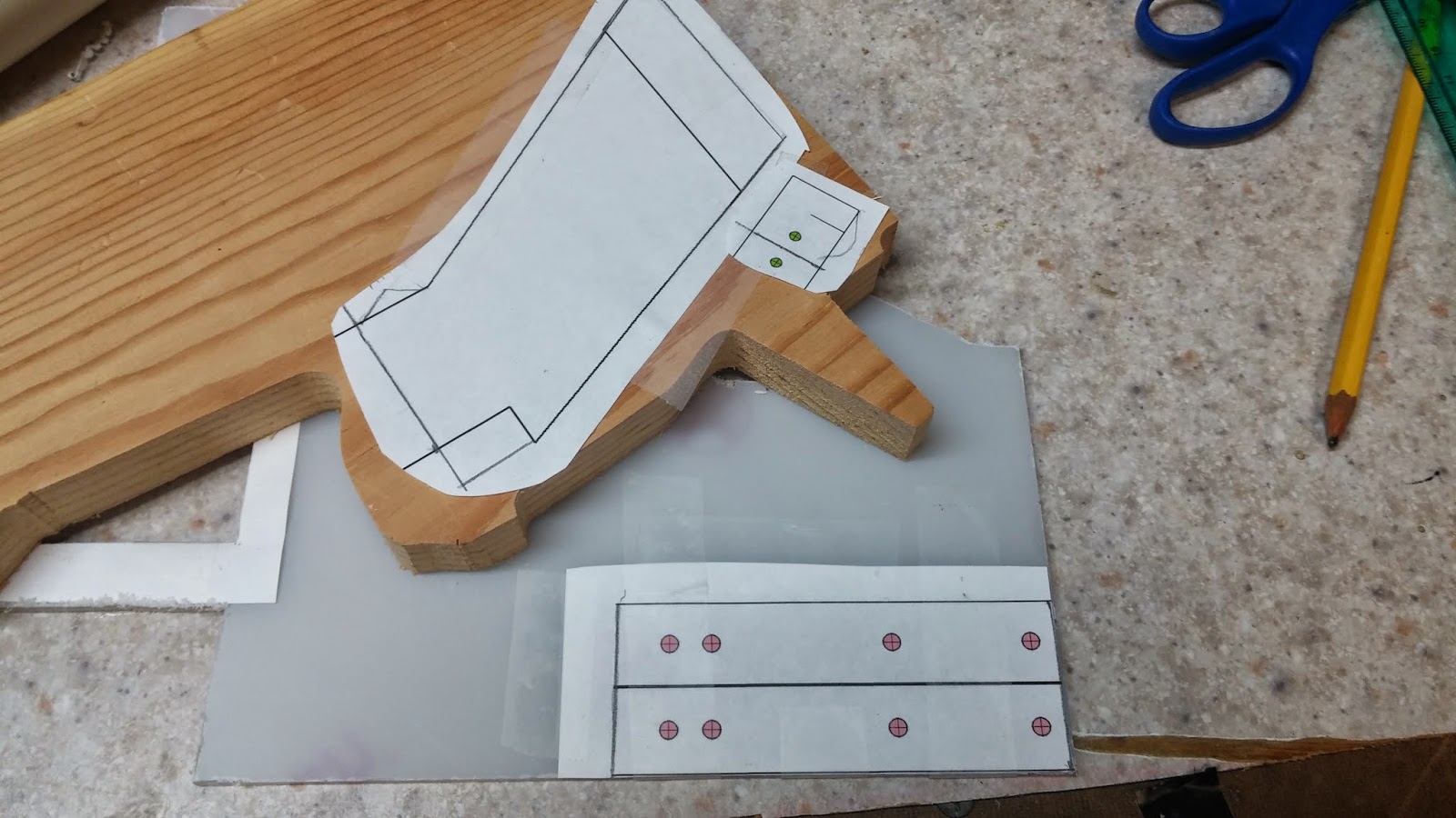
20140326_105126.jpg

Cut out these pieces on your scroll saw. Once you are done, it should look like this:
20140326_110519.jpg

Drill the holes using the key from the template (5/32 for the polycarbonate, 7/64 for the trigger guard). After that, take the paper off.
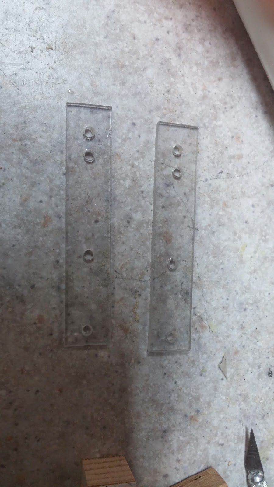
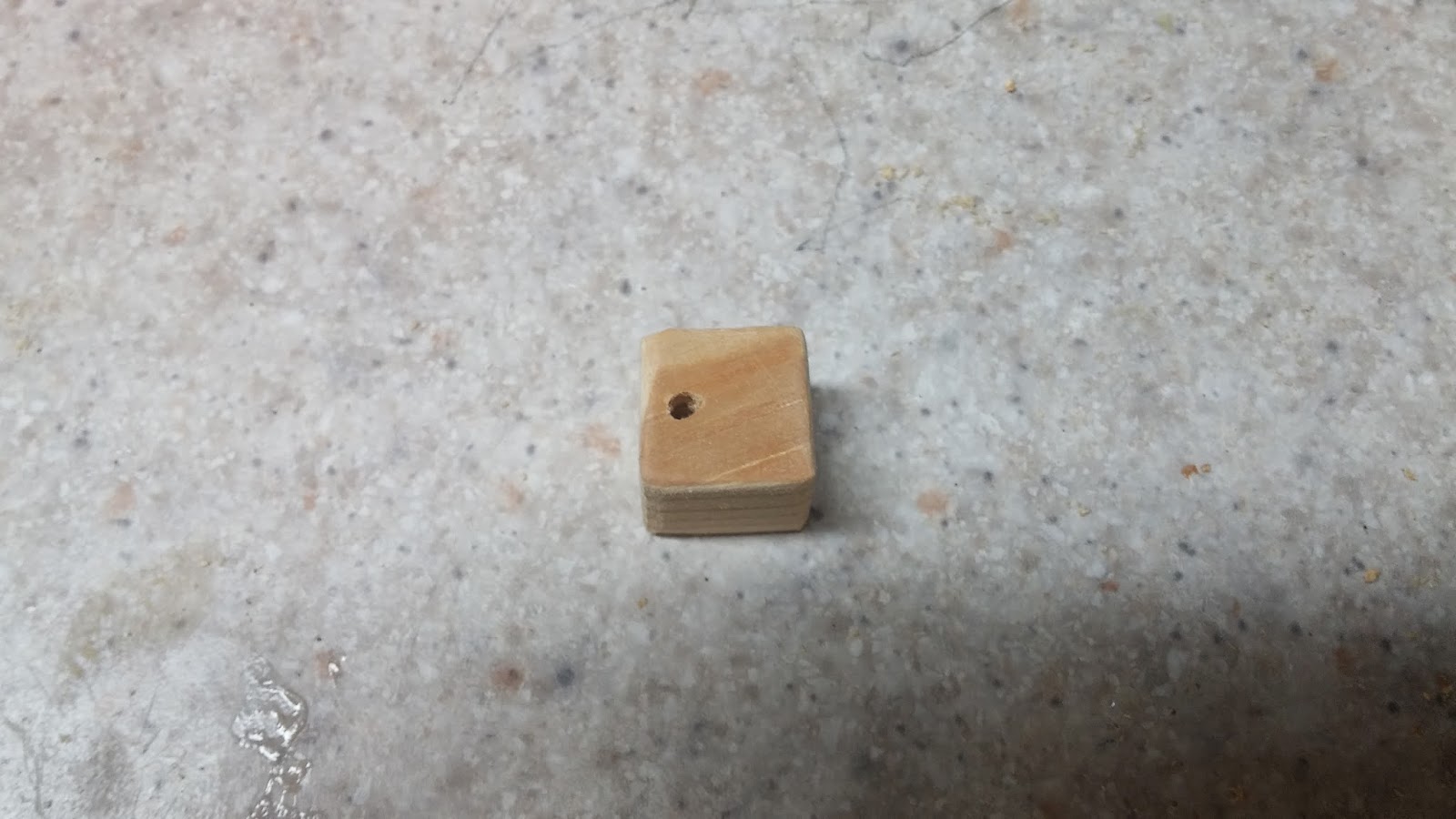
20140326_115723.jpg
20140326_120122.jpg

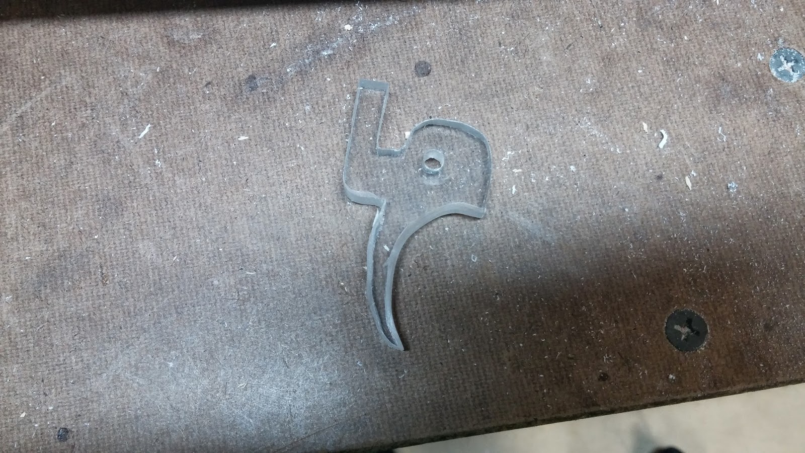
The final part of the templates is the trigger. I attached the trigger template to the polycarbonate and then modified it to look like this. You can make the trigger in any way you want except you have to have the 1.5cm rectangle part at the top. This can be seen in the picture and it is very important.
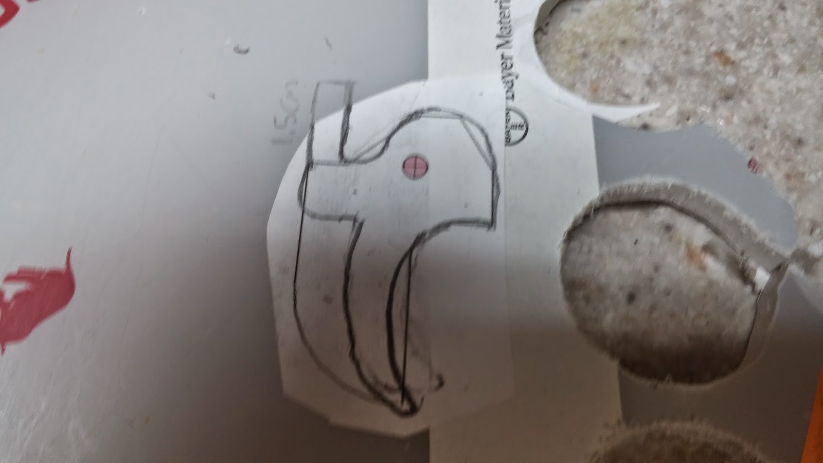
20140326_140108.jpg

Next cut out the trigger. You can sand it down to make it more comfortable if you want.
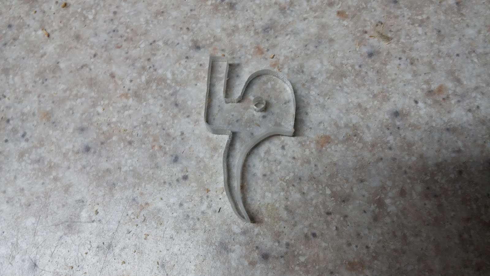
20140326_141321.jpg

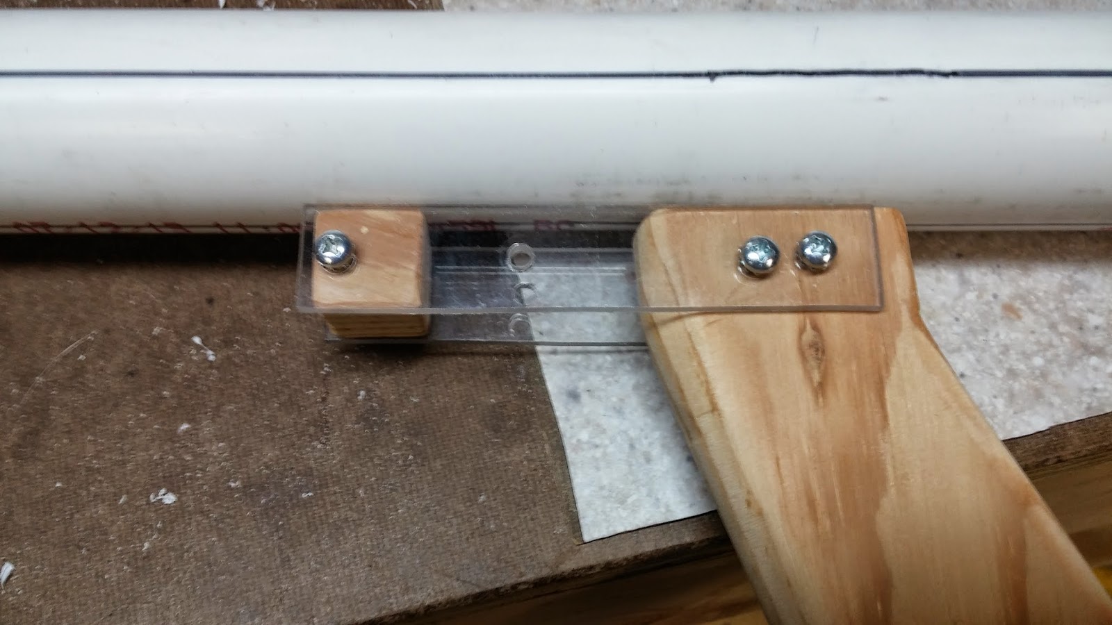
Now you want to put the handle together. The first thing you want to do is to attach the trigger sideplates to the trigger guard with 3/8" 6-32 screws. You can also attach the trigger without the washers to help with alignment. To do this just use a 1 1/4" 6-32 screw and a 6-32 locknut. Line up the trigger sideplates on the handle like so and mark where the holes are with a pencil. Drill the holes on both sides with a 7/64" drill bit.
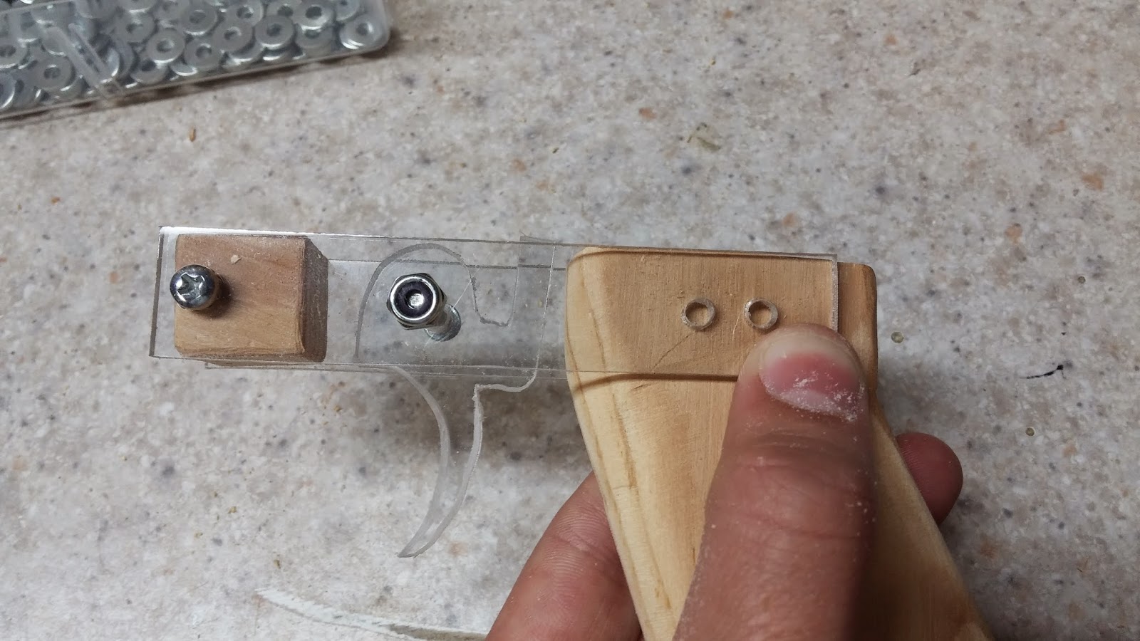
20140326_141621.jpg

Screw on the handle with more 3/8" 6-32 screws and put five washers on each side of the trigger (if five washers is too tight, use fewer). Your handle assembly is now finished.
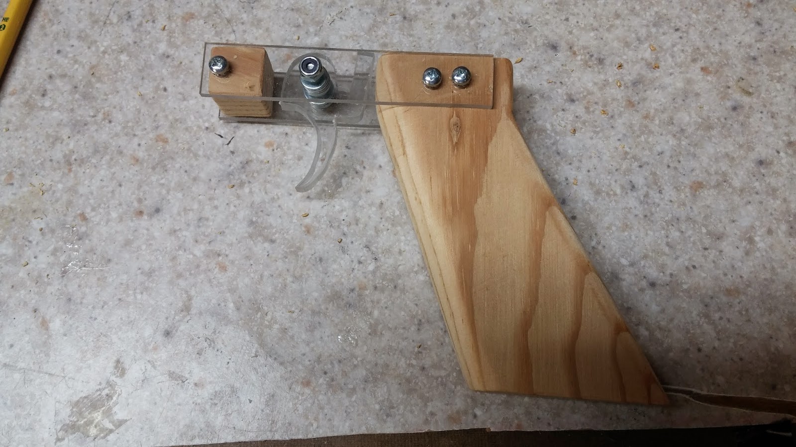
20140326_142539.jpg

Next is the plunger head and plunger rod. To make the plunger head, you will need polycarbonate and the u-cup. First put the u-cup under the circle template and find a circle that is a little bit bigger than the u-cup.
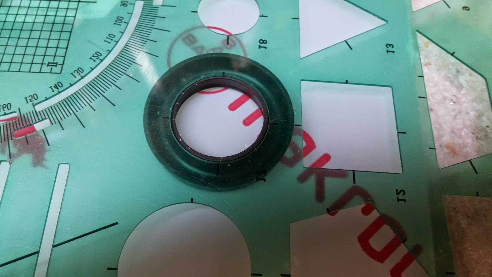
20140327_102037.jpg

Trace two of these circles onto the polycarbonate. You will also want to trace the inside of the u-cup onto the polycarbonate. Do your best to draw a dot in the center of all three circles. A good way of doing this is by making two perpendicular lines through each circle and drawing the dot at the intersection.
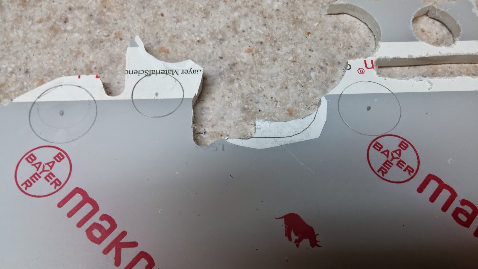
20140327_102337.jpg

Cut out the circles with the scroll saw and drill a 5/32" hole through each center dot. It can be hard to cut circles on a scroll saw, so what I recommend is to cut a crude circle-ish shape bigger than the needed circle and then sand it down with a dremel or even sandpaper until it resembles a circle.
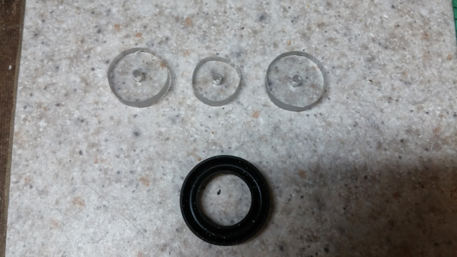
20140327_103611.jpg

For the plunger rod, you will want two 1 1/4" 6-32 machine screws and the nylon rod. Cut the nylon rod to 13". Now on the piece of nylon rod, measure 3 1/4" into it and make a cut using any kind of saw that you want.
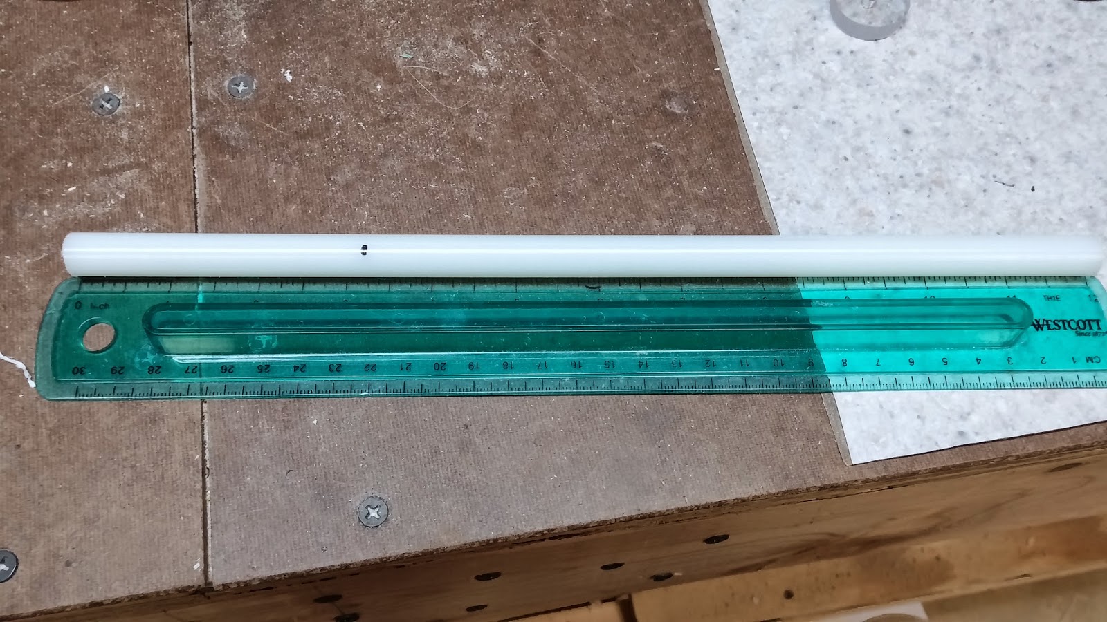
20140327_104105.jpg

Make dots in the center of the ends of both rods except for the long one. The long rod only needs one hole. Drill a 7/64" hole into the rod where you made the dots and make sure that the holes are about 3/4" deep. Tap the holes with your 6-32 tapping bit.
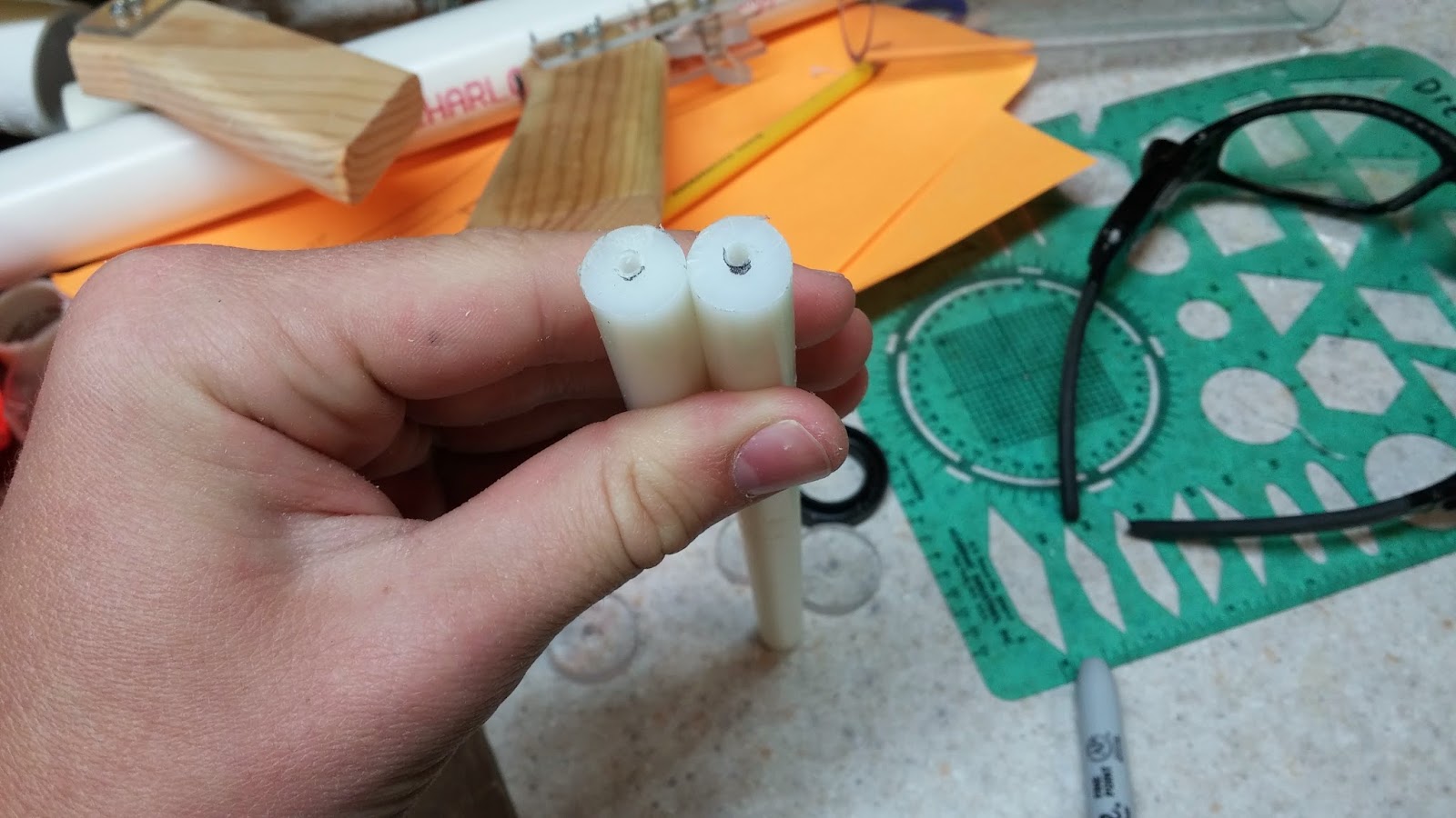
20140327_105206.jpg

Secure the plunger head assembly on to the 3 1/4" piece of nylon rod with a 1 1/2" 6-32 screw. The small polycarb circle should be in the middle of the u-cup and the other two pieces should be on the top and bottom.
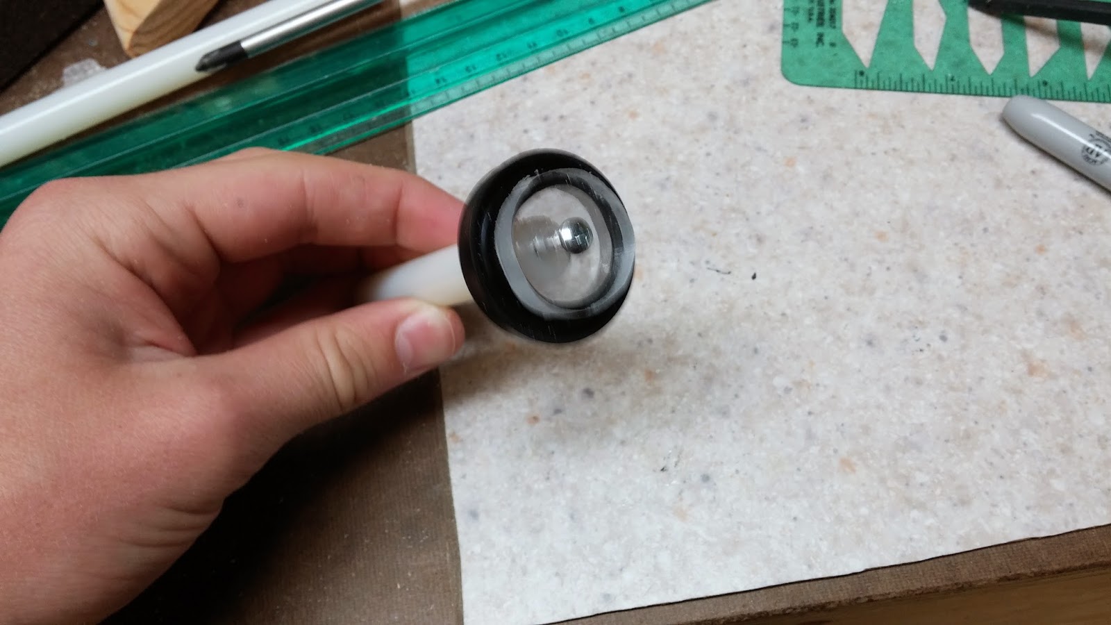
20140327_105449.jpg

Now take another 1 1/2" 6-32 screw and cut the head off of it like the one in the picture below. This can be done with mini bolt cutters or some kind of cutting tool that looks like the one below. You can also cut the head off if you clamp down the screw and use a hacksaw.
20140327_105702.jpg

Thread the screw into both pieces of nylon rod. Screw it in evenly and make it so there is about a 1/2" gap between the rods. I recommend gripping the screw with pliers to help get it into the rod. To make sure the whole plunger rod assembly is straight, slide the piece of 1/2" PETG over it. If it isn't straight, make adjustments until it is.
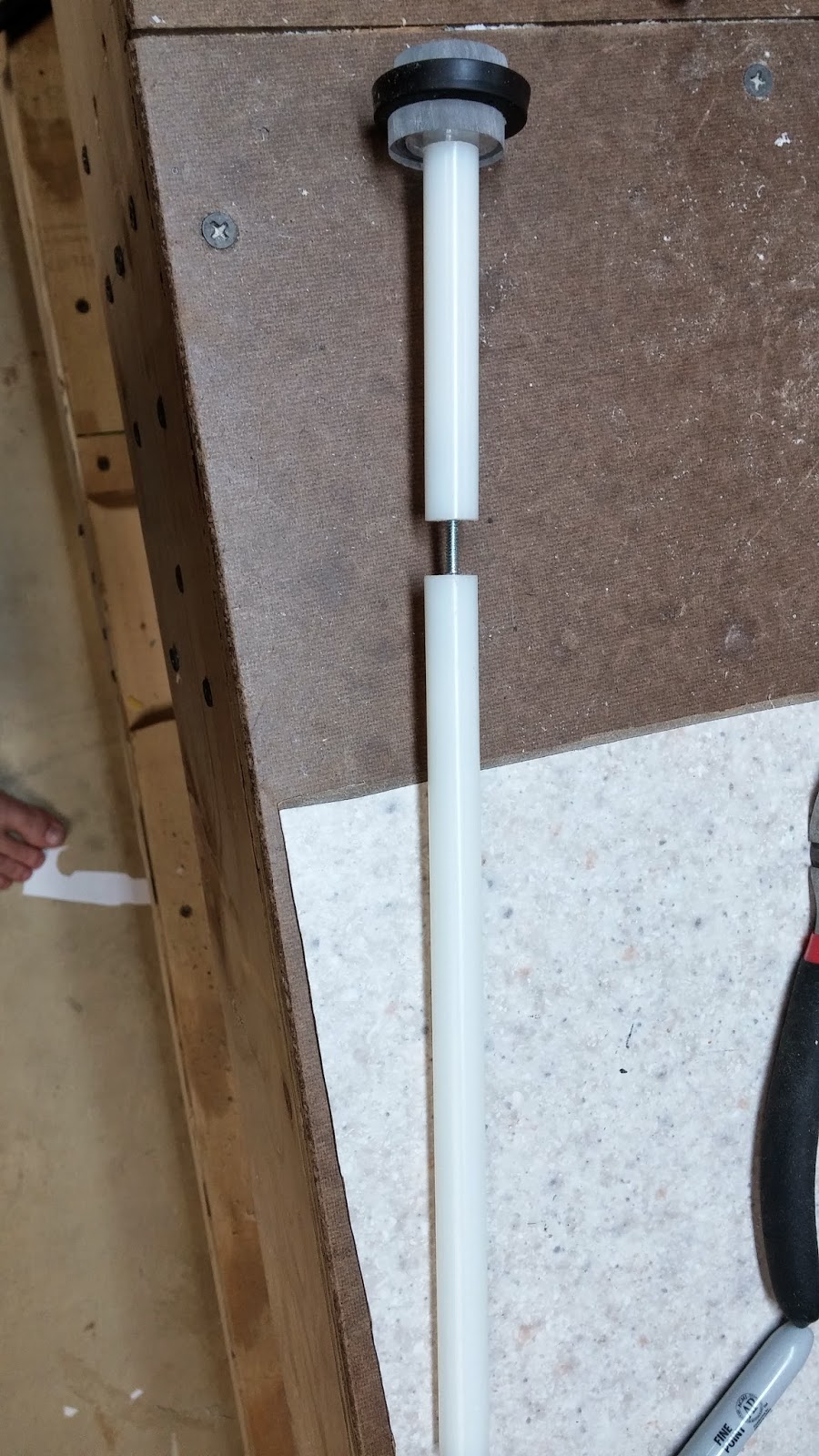
20140327_110603.jpg

Now that the plunger assembly is finished it is time for the catch! This catch is a modified version of the rainbow catch that is scaled down to fit into 1" PVC. To start off you want to find a circle template that would almost fit in 1" PVC. It's ok if it is a little bit bigger but it can't be smaller. Draw three of these circles onto your polycarbonate, make a mark in the center, and drill a 5/32" hole in them.
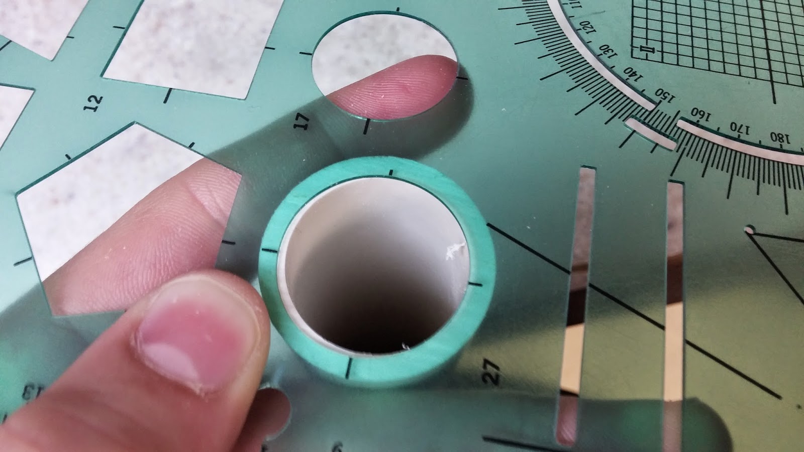
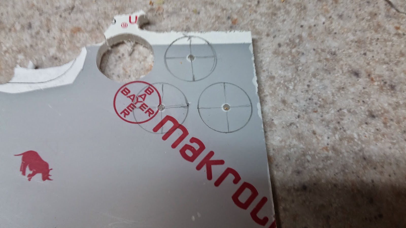
20140328_102149.jpg
20140328_102901.jpg

Using the 1/2" spade bit, drill holes into the circles using the previously drilled holes as a guide. You are going to also want to cut catch piece like what is seen in the top circle. There are no specific measurements for this, but just try to replicate it the best you can.
p+(1).jpeg

Here are the pieces cut out. Make marks on the circular pieces of where you are going to drill the holes. To help with this, line up the middle (catch) piece with the hole in the circle piece and then make the marks on the outside of the catch piece. The marks should be around the area of where they are in the picture.
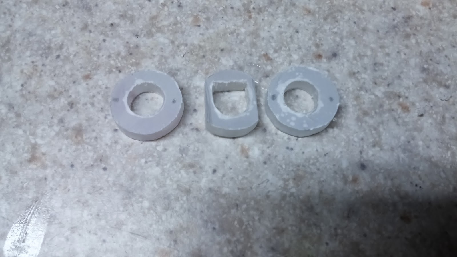
20140328_105650.jpg

Drill those holes and tap them with the 6-32 tapping bit. There are four holes in the picture because I actually messed up the first time and made the holes too close together. Ignore the holes on the top and bottom of the pieces.
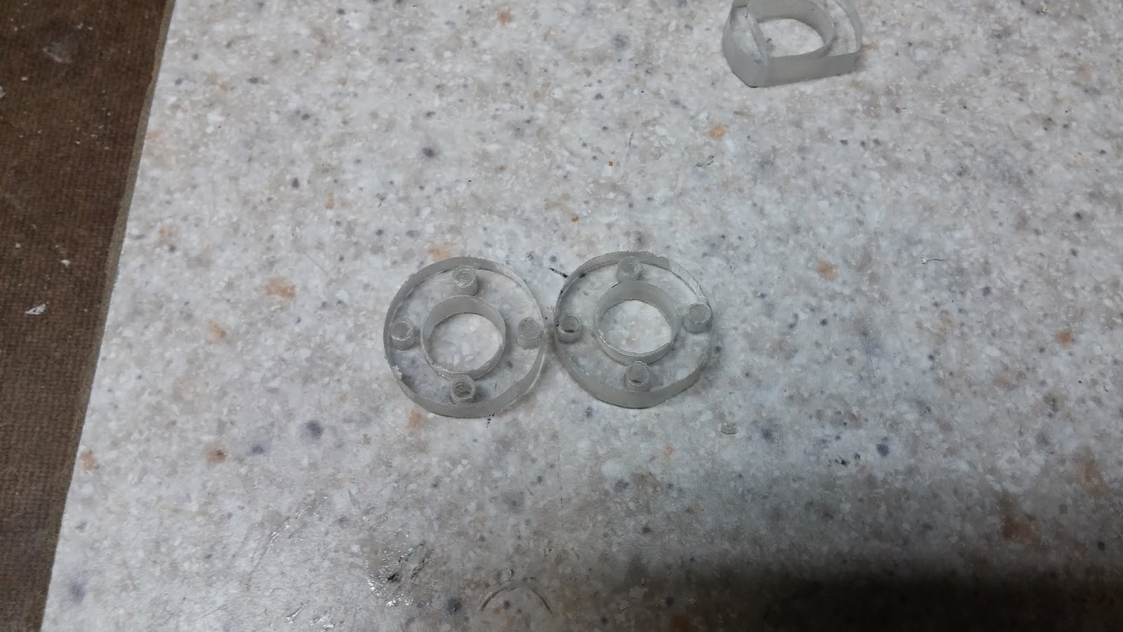
20140328_114000.jpg

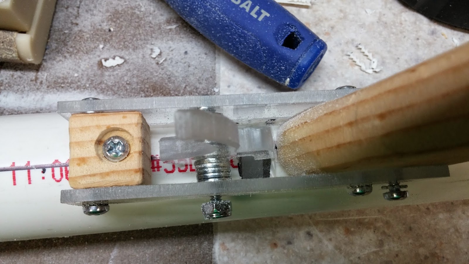
Screw together the catch using 3/4" 6-32 screws. It is good if the screws are hanging off the side a little bit. This picture shows the two circular catch plates and the actual catch piece fitting in between them. If your catch plate does not fit, sand down the edges until it does.
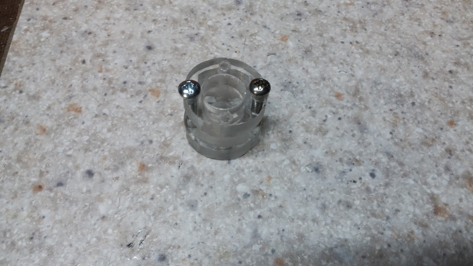
20140328_113513.jpg

Once you make sure that the catch is put together properly (the catch piece can freely slide through the catch plates and the catch fits in 1" PVC), you can sand the overhanging screws down. Do this with your dremel's sanding bit or it will take forever. Now the catch should be able to fall all the way through 1"PVC. Cut the 1" PVC to 11.5"

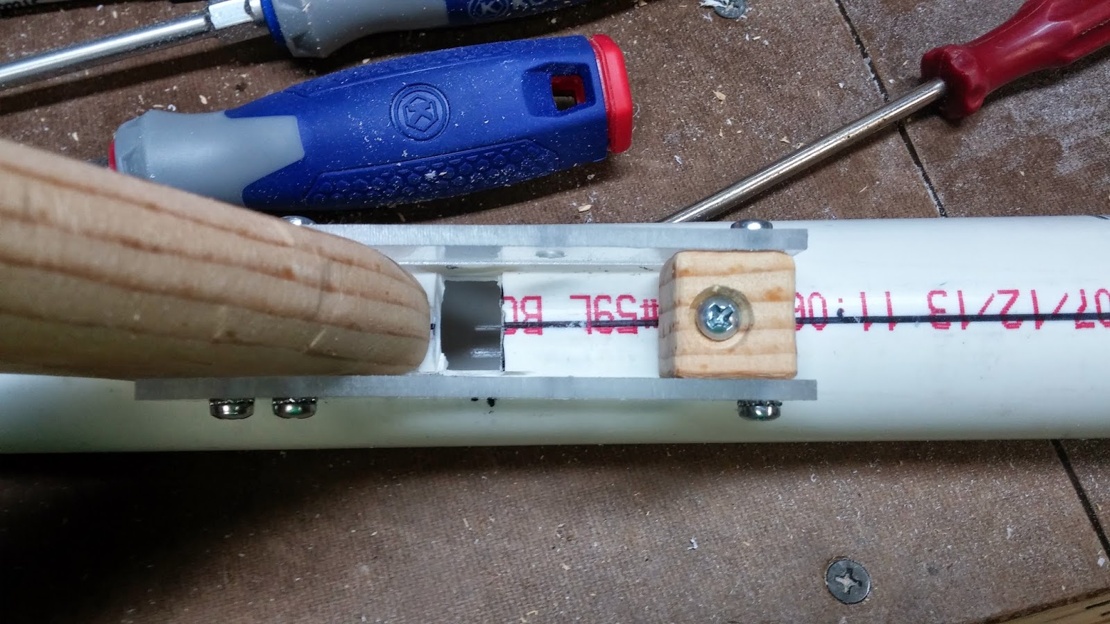
Line up the actual catch piece with the 1" PVC like this and draw lines on the outside of the catch piece.
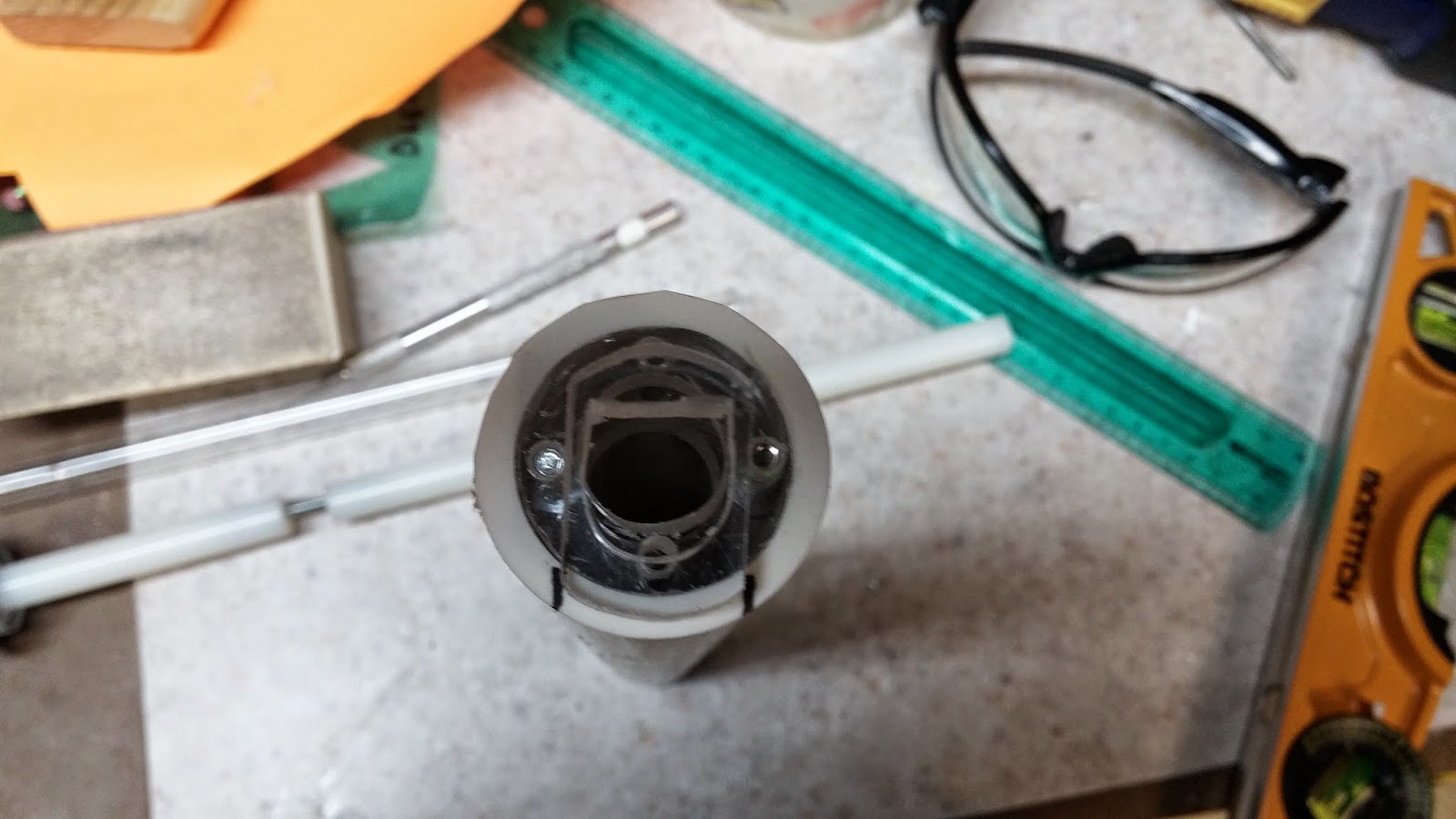
20140328_125618.jpg

To fasten the catch to the 1" PVC, you want to out the catch plates in the PVC so that the screws already in the catch are facing away. Make sure that the catch is flush with the end of the PVC and make 3 marks of where you are going to drill. You will be drilling into the front catch plate without the screw heads. Drill the three holes with a 7/64" bit and tap them with the 6-32 tap. Finally, fasten the catch with three 3/8" 6-32 screws. Everything is better explained in the picture.
20140328_130709.jpg

Extend the lines you drew earlier to be the length of the catch.
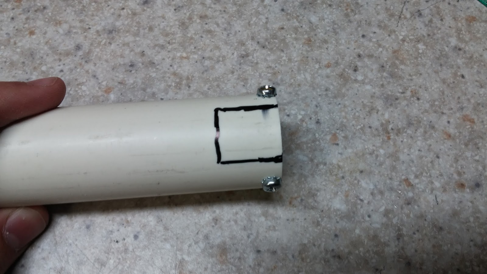
20140328_131023.jpg

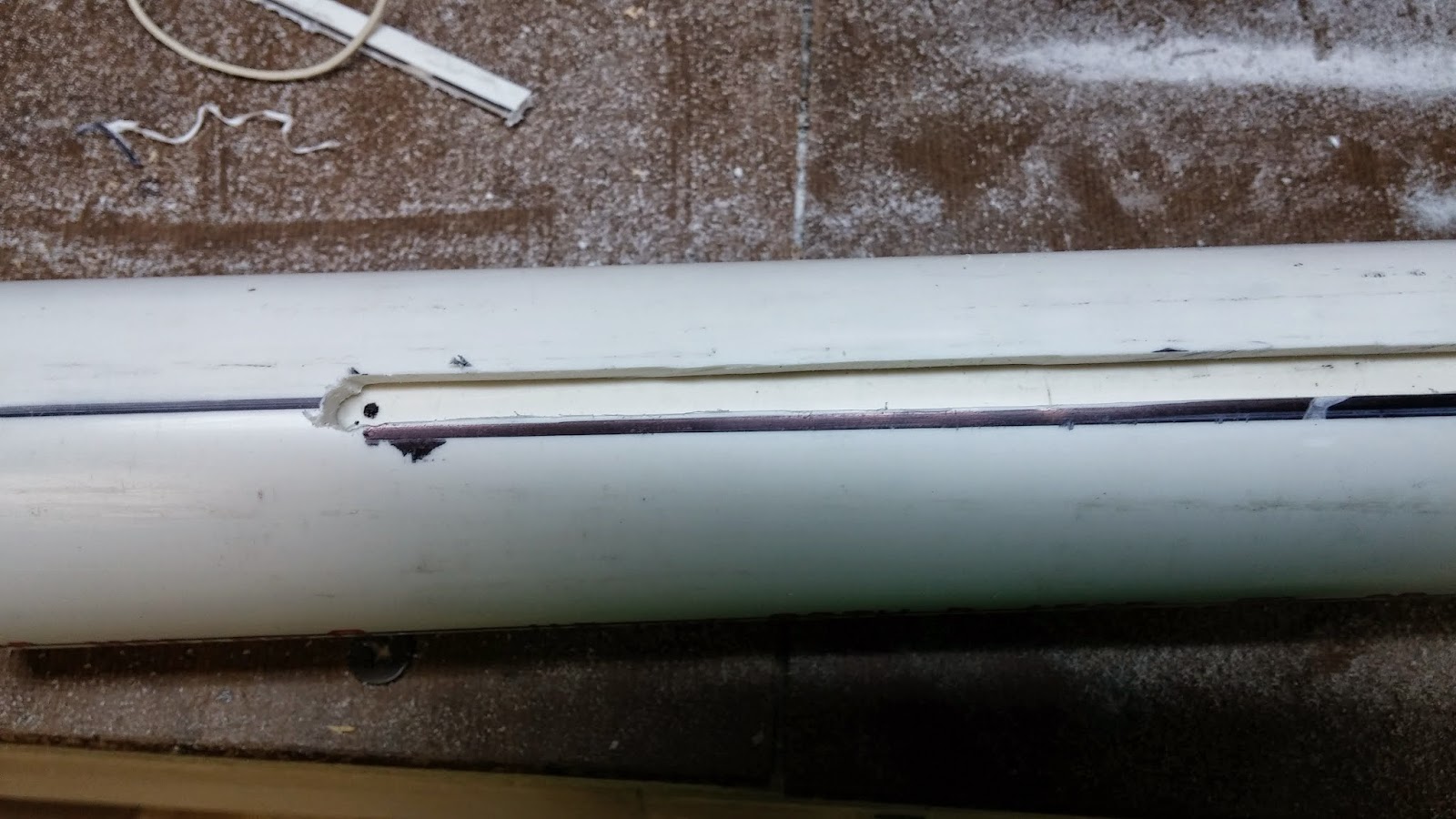
Cut out these lines with a cutting disc on the dremel. The below picture will also help with figuring out how to fasten the catch.
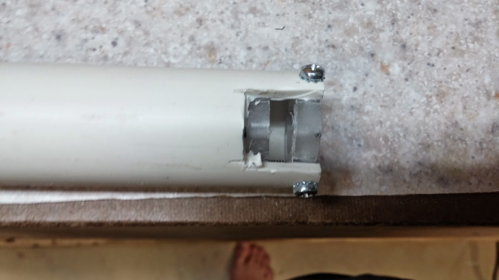
20140328_131652.jpg

Cut the heads off of the screws that you used to fasten the catch. Use the same tool that you used earlier to cut the long screw. Screw the catch back in. I could screw the screws in all the way without using any tools, but if you are having trouble grip the screws with some pliers and screw them in.
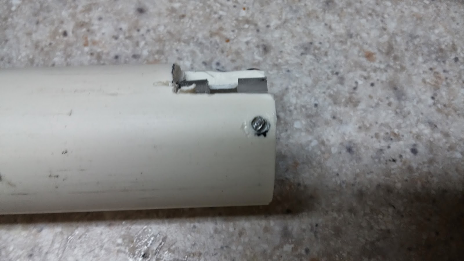
20140328_133909.jpg


Edited by Aeromech, 23 November 2015 - 02:48 AM.

  • 1
Check out my blog: Fly Nerf

#2 Drev

Drev

    Member

  • Members
  • 135 posts

Posted 26 May 2014 - 08:25 PM

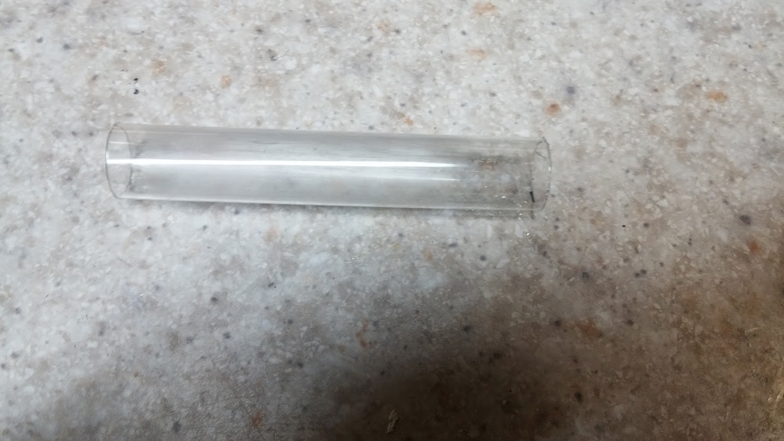
Time to use the PETG. Cut the PETG to 3.5".
Posted Image

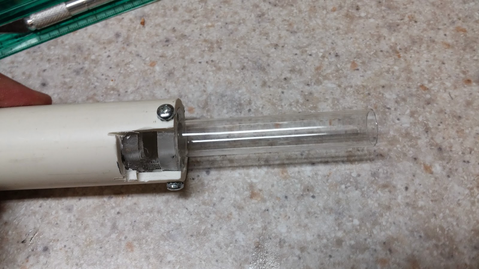
Use your dremel sanding bit to widen the hole on the front catch plate until it snugly fits the PETG in it. Super glue the PETG in and you will be almost done with your catch.
Posted Image

This next part has an easy option and a hard option. The easy option will work, but the hard option is much more reliable.
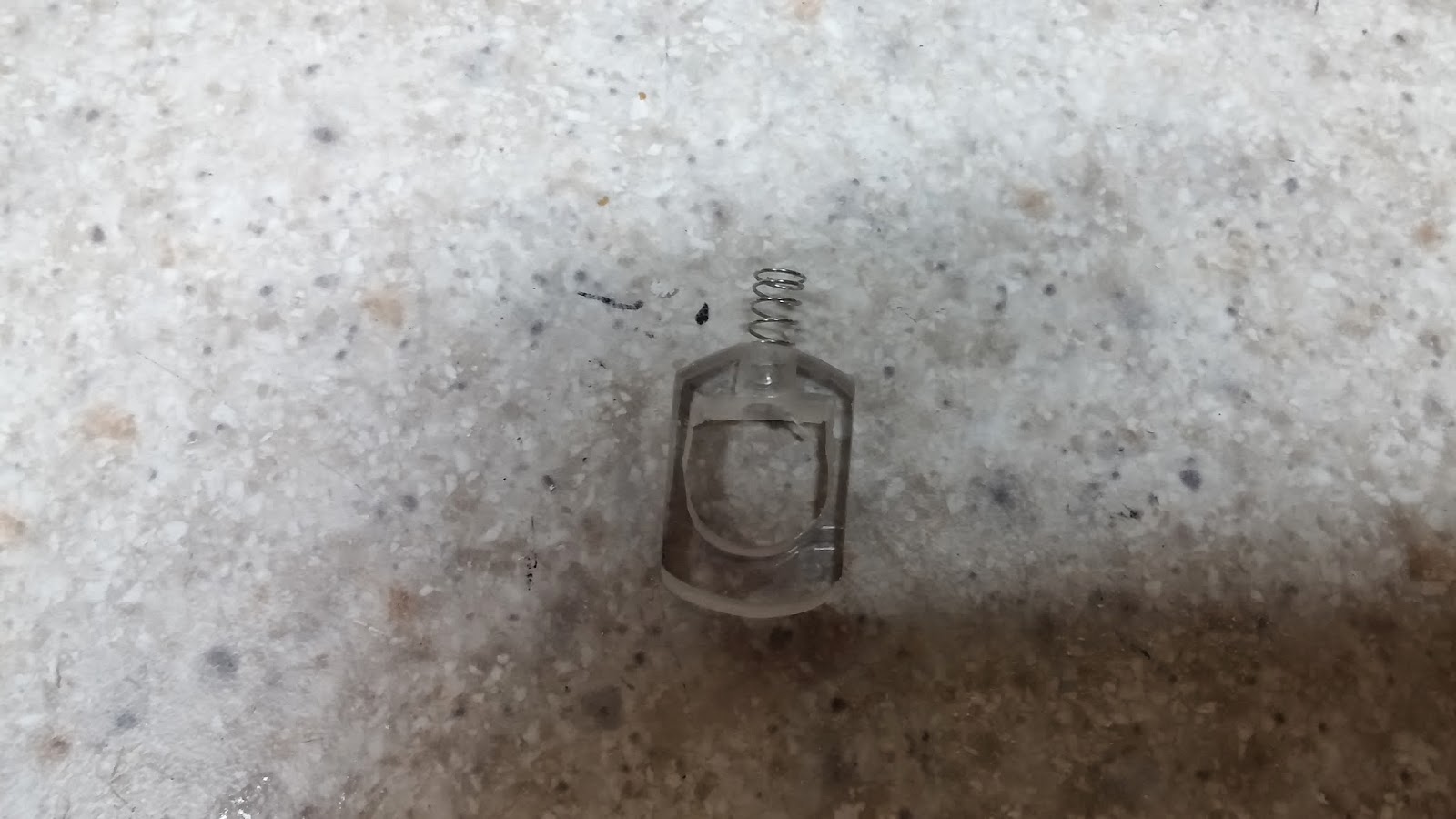
Easy: Take your nitefinder/maverick catch spring, cut it to a length that looks like the length sticking out of the catch piece in the picture below, and hot glue or super glue the spring on.

Hard: You want to drill a hole in the top of the catch piece that will be able to fit the maverick/nitefinder catch spring in it. Don't drill the hole all the way through so that the spring will stay in place. I start with a small drill bit like 7/64" and work my way up to whatever size will fit the spring. If you don't have a lot of drill bits, just use a hobby knife to slowly carve away at the hole.
Posted Image

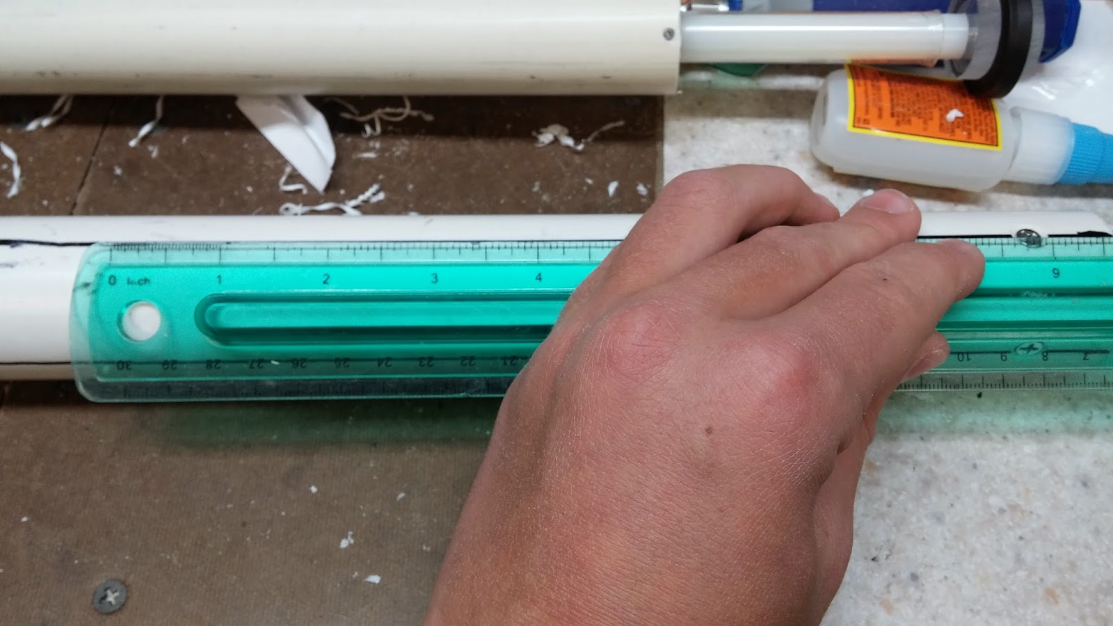
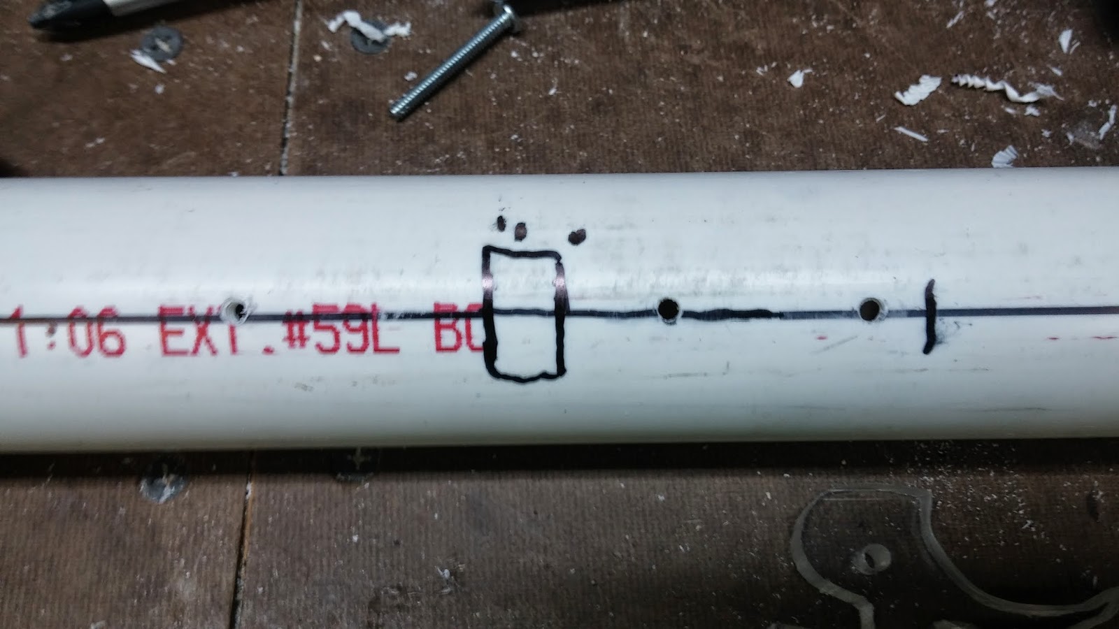
Now that the catch is done it is time to fasten the handle. To do this, measure 9.5" from the end with the bushing and make a mark.
Posted Image

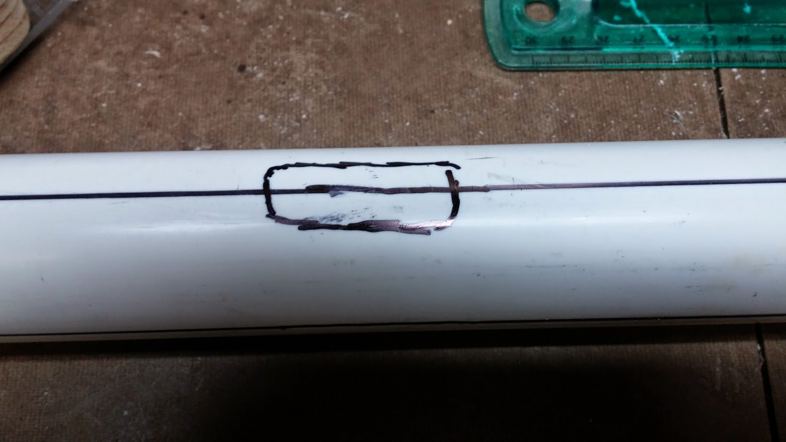
Measure 2" from that mark and make another mark. Connect the marks with lines so it forms a rectangle with rounded edges.
Posted Image

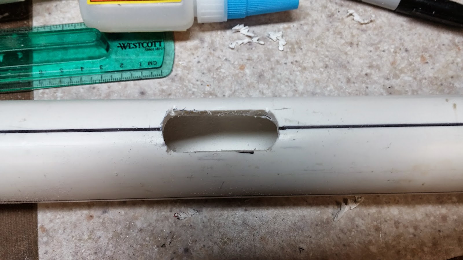
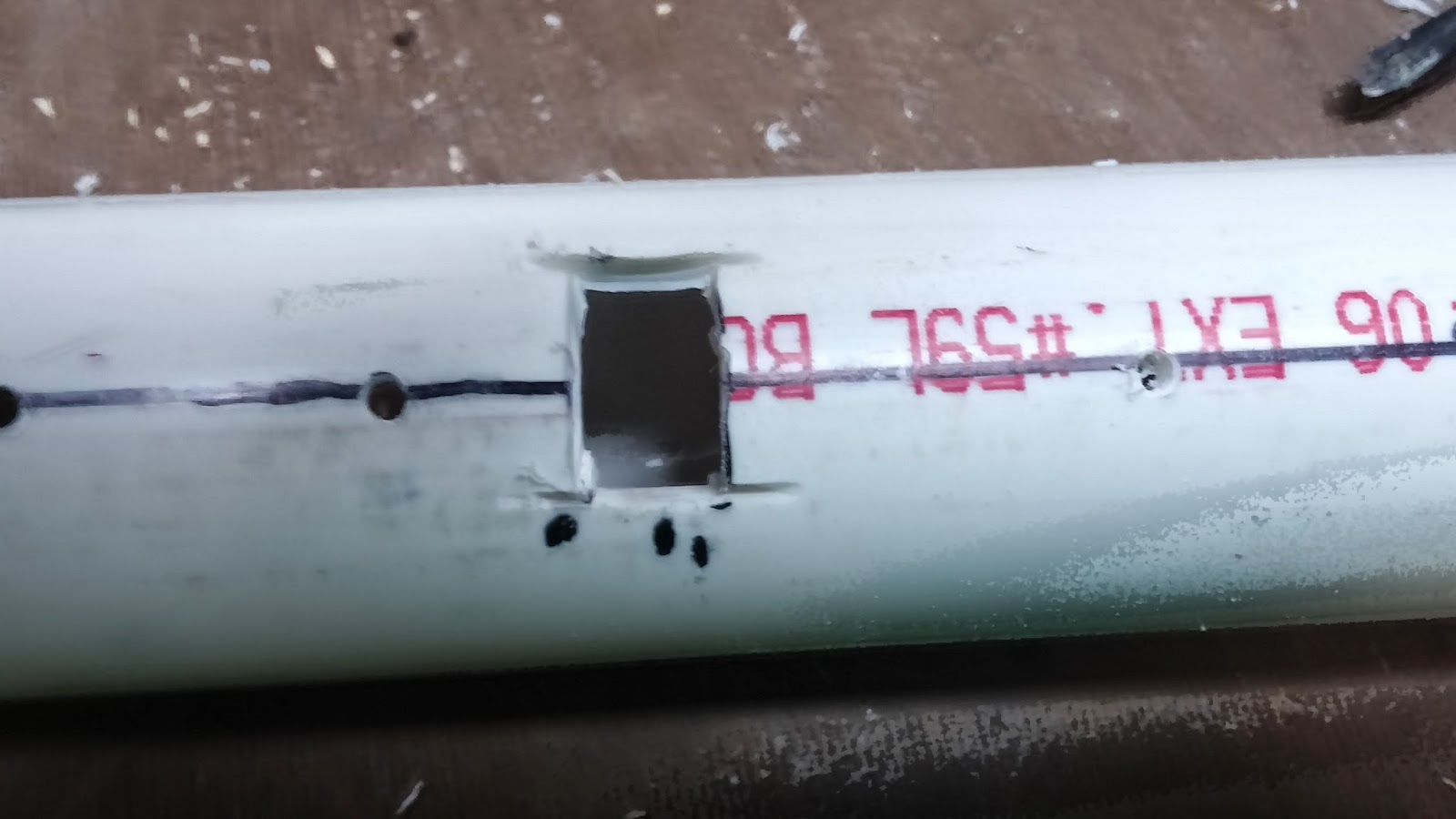
Cut out the shape you just made using the cutting disc on your dremel. Use the sanding bit to sand the edges and make them round.
Posted Image

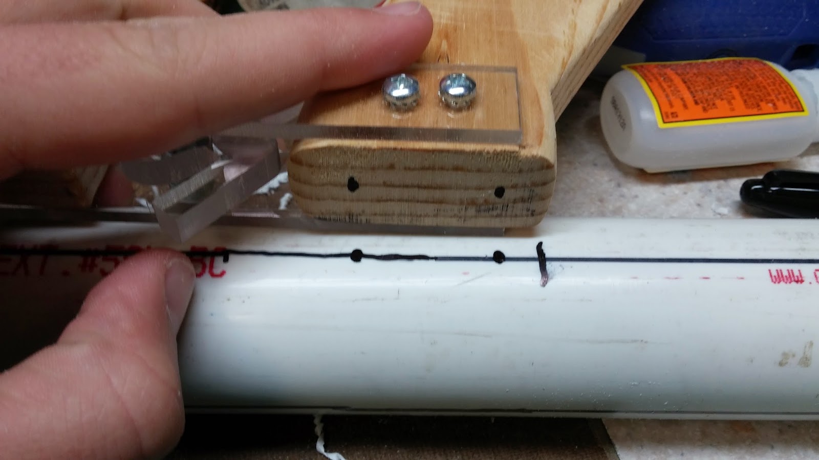
Now on the opposite side of the PVC from where you made the hole, measure 9.75" from the end with the bushing and make a mark. Draw two dots on your handle of where you are going to want to screw it in. Line up the back side of the handle with the mark and create two dots on the PVC that are lined up with the dots on the handle. Once you do that, drill holes into the PVC where you made the dots with a 7/64" bit and tap the holes with a 6-32 bit.
Posted Image

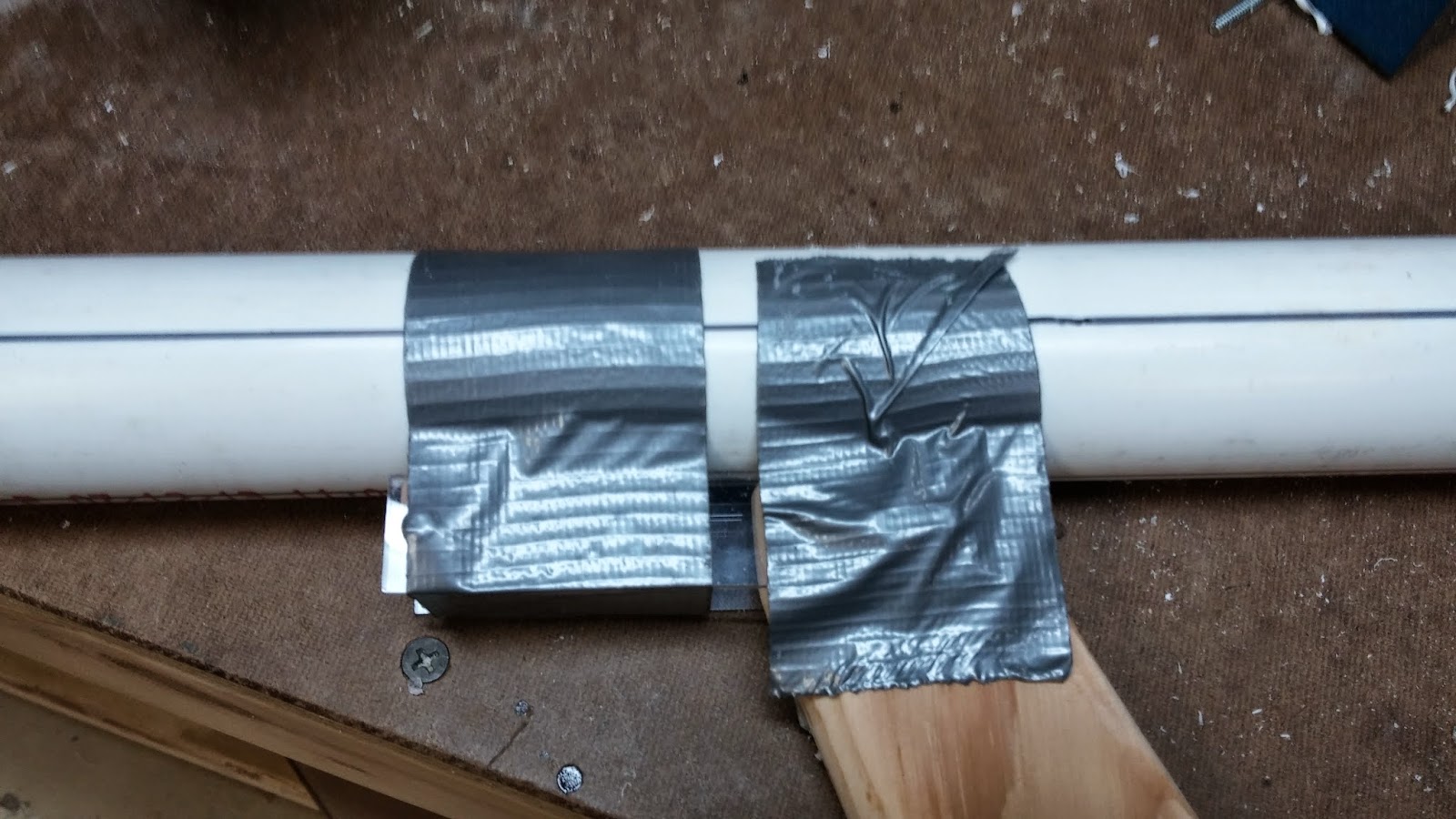
Now tape the handle onto the PVC using duct tape. It helps if you take off the trigger. Try to line up the handle with the holes you just drilled and make sure that the handle is as straight as possible.
Posted Image
Posted Image

There is no picture for this step, but what you want to do is drill through the holes that you just made with a 7/64" bit from the top of the PVC (the big hole). You don't need to be able to drill all the way through, you just need to make marks on the handle.
Posted Image

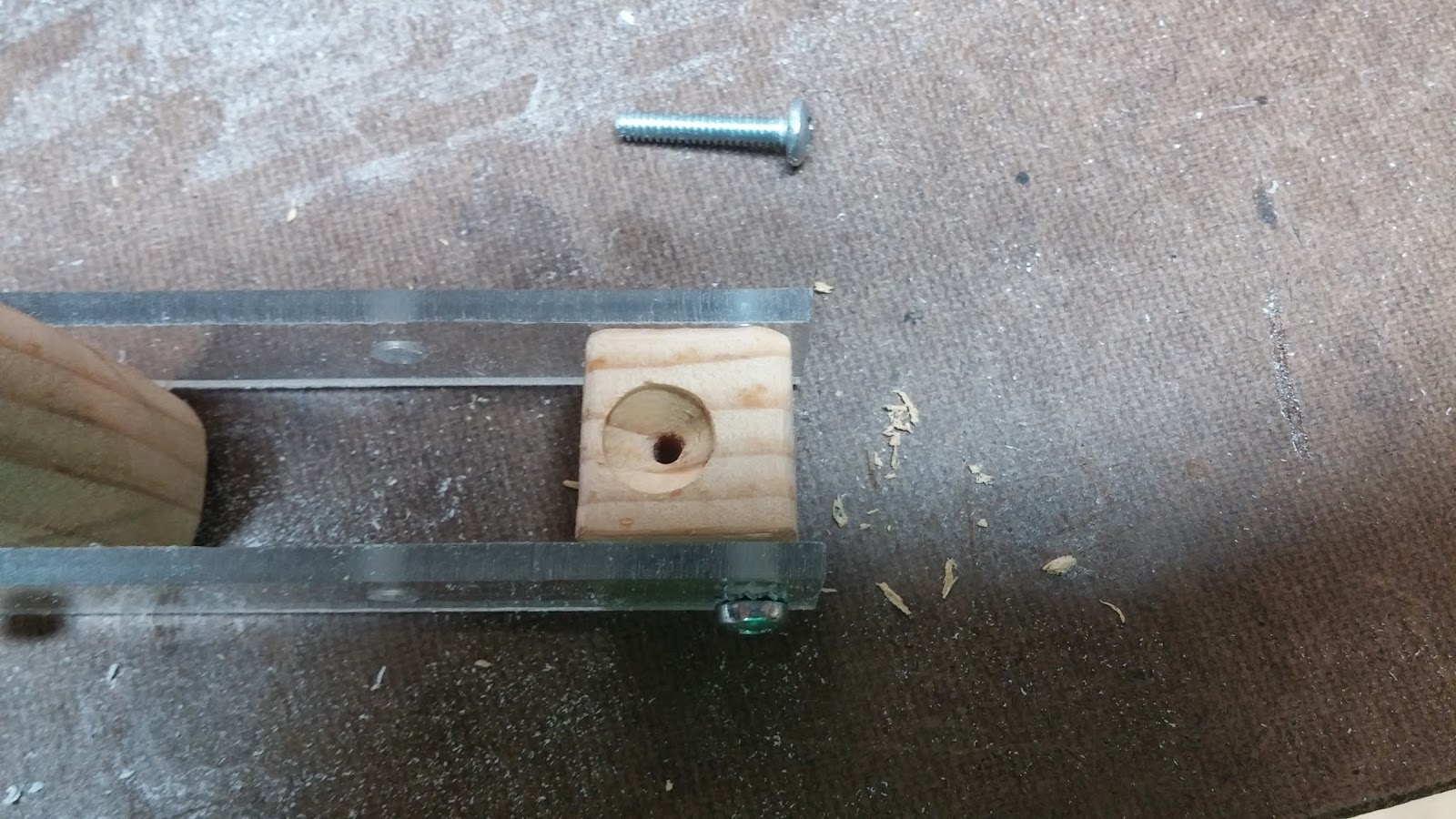
With your 7/64" bit, make the holes in the handle deeper. 3/4" to 1" deep holes should probably suffice. Now line up your handle again and screw it in using the flathead 3/4" 6-32 screws.
Posted Image

Drill through the front wooden piece on the handle assembly with a 7/64" bit until you drill into the PVC.
Posted Image

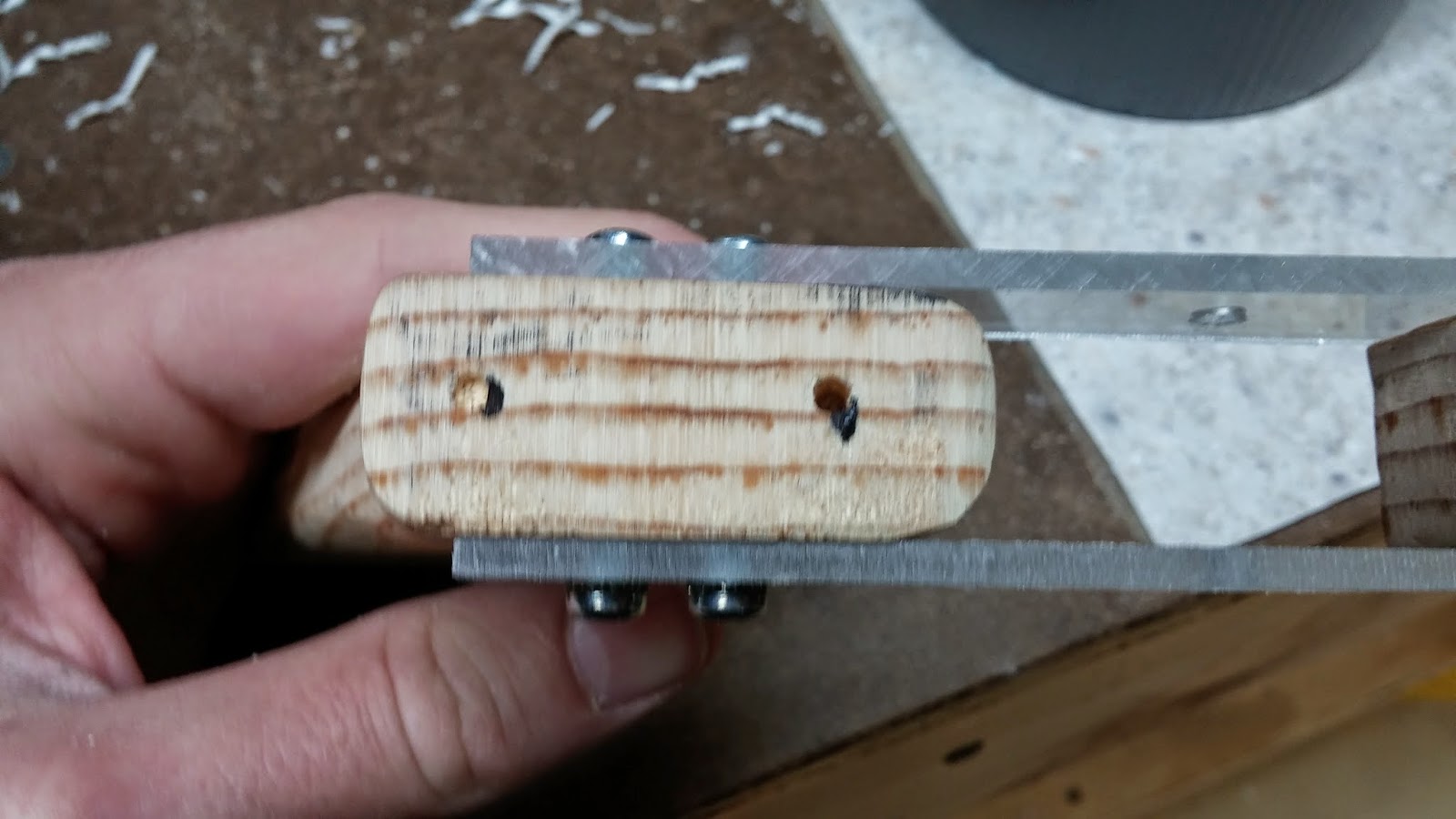
Now remove the handle. Tap the hole in the PVC that you just made in the previous step with a 6-32 bit. Countersink the holes you made to attach the handle with your countersink bit and countersink the front wooden piece on the handle assembly.
Posted Image
Posted Image

Line up the handle assembly with where you would attach it. Also line up the trigger where it would normally go on the handle and make a mark where the back bump part of the trigger touches the PVC. There aren't pictures for this step but you should be able to figure it out. Here's a picture of the trigger again so you can understand what the bump that I'm talking about is:
Posted Image

You have two options now. You can drill a hole big enough for the trigger to fit through at the mark or you can draw a rectangle around the mark and cut it out with your cutting disc. I opted for the second method, but either one will work.
Posted Image
Posted Image

Fasten the handle on again and this time use a 3/4" 6-32 screw to screw in the front wood piece from the bottom. You can also put the trigger on now.
Posted Image

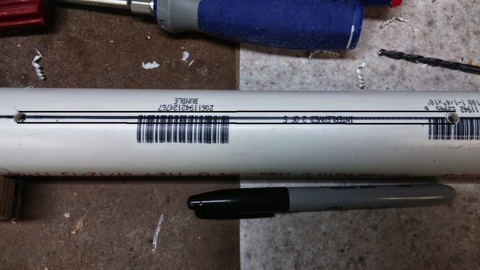
Now onto the slots. To make the slots, measure 1/2" from the front of the handle assembly and make a dot on the line on the side of the PVC. Do this on the other side too. Now measure 7.5" from the dots and make another dot. Drill into these dots with a 11/64" drill bit.
Posted Image
Posted Image

Now it's time to connect the holes. First draw lines using a ruler from the top of one hole to the top of the other and the bottom to the bottom.
Posted Image

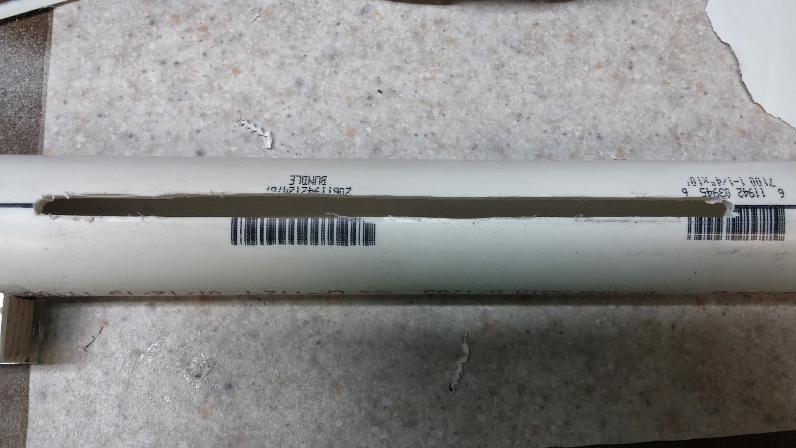
This next step takes patience. You are going to want to cut across the lines that you just drew with your dremel's cutting disc. Don't cut too fast because you really want these lines to be straight. Remember to cut the slots on both sides. Clean out the PVC dust that has accumulated in your blaster. You don't want any in there.
Posted Image

Grease the plunger head with white lithium grease or silicon grease. Slide the plunger assembly all the way through the body until it hits the bushing. You want to move it back and fourth a few times to spread the grease throughout the plunger tube. Take the plunger assembly out, re-grease it, and repeat the above steps to make sure the plunger head will be able to move. After this, put the [k26] spring on the plunger rod and push the whole catch assembly into 1.25" body and onto the plunger rod. Line it up so you can see the catch through the hole for the trigger.
Posted Image

Make a mark on the 1" PVC (catch assembly) where it is lining up with the front of the slot. Do this on both sides like always. Drill into these dots with a 7/64" bit and tap the holes with the 6-32 bit.
Posted Image

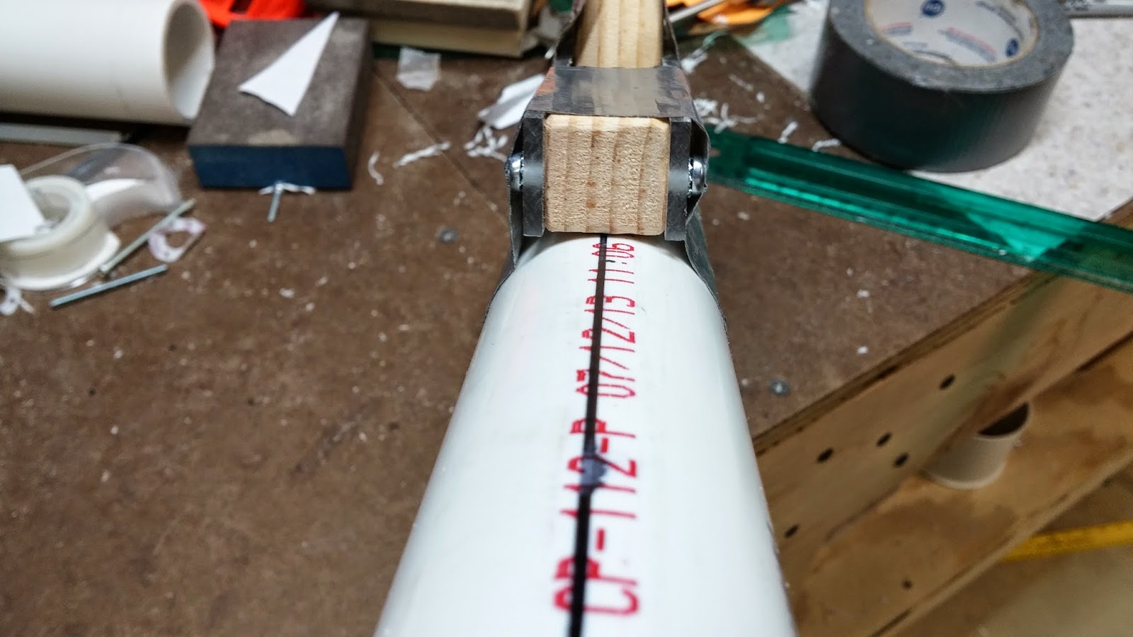
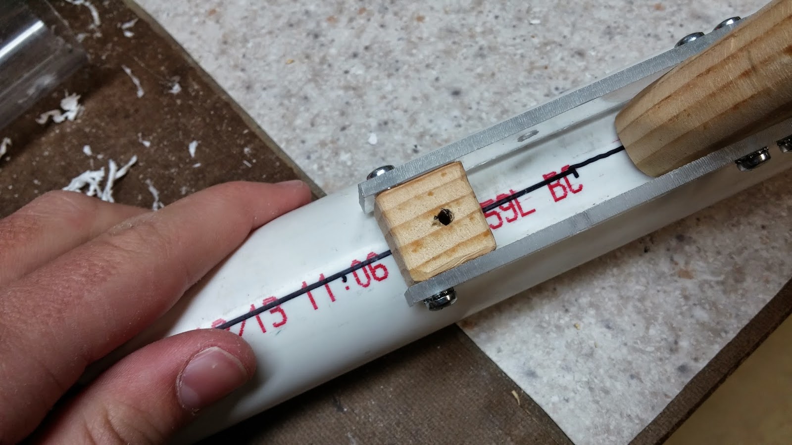
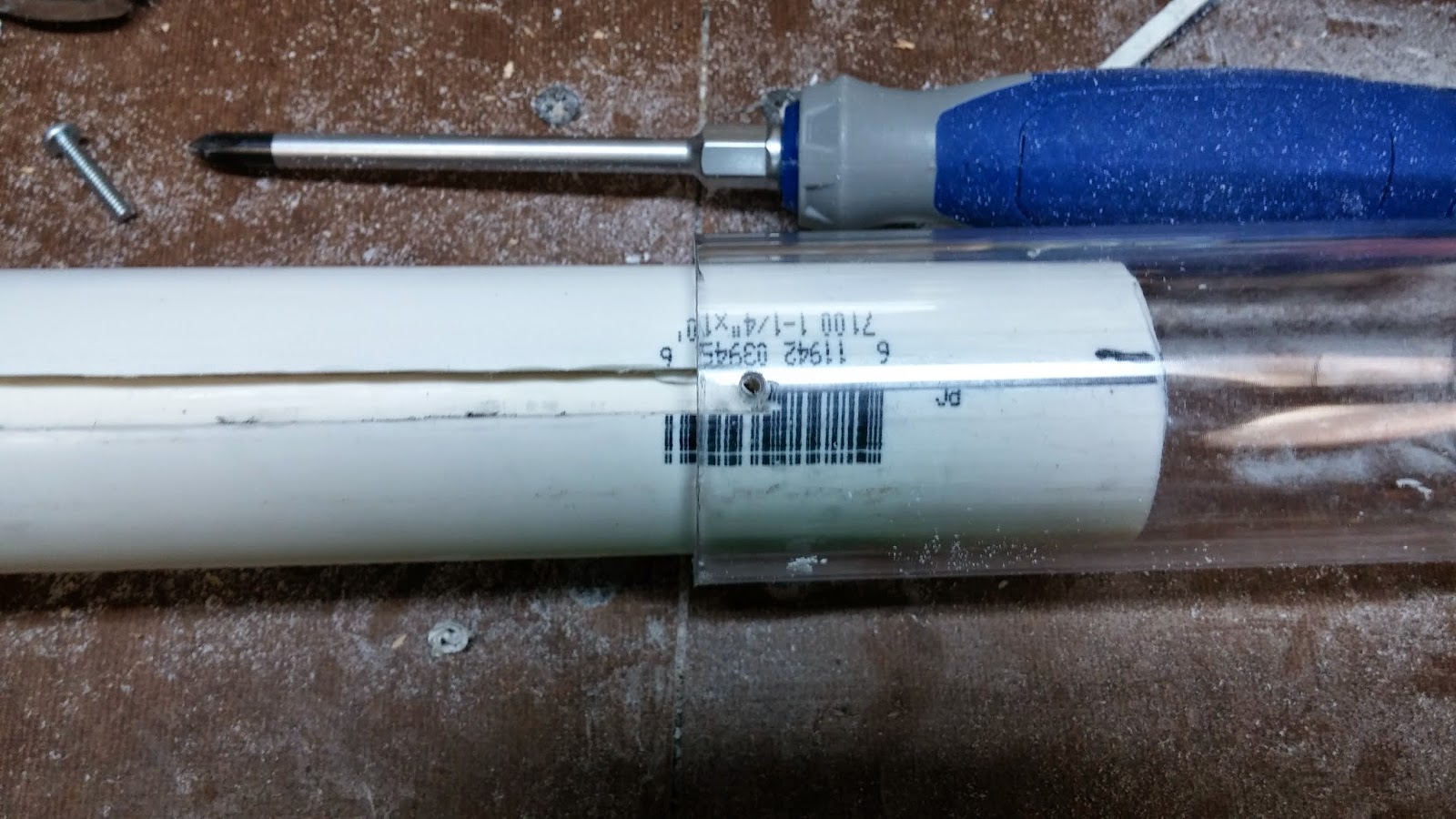
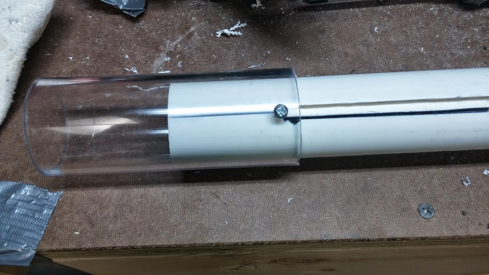
Take the 2" OD PETG and cut it to 5" long. Put it onto the blaster and line it up with the holes that you just drilled in the 1" PVC. You want to have about .5" of PETG behind the marks you made. Drill the marks with a 7/64" bit and tap it for 6-32. The picture should explain everything a little bit better.
Posted Image

Screw the the PETG onto the 1" PVC with 3/4" 6-32 screws.
Posted Image

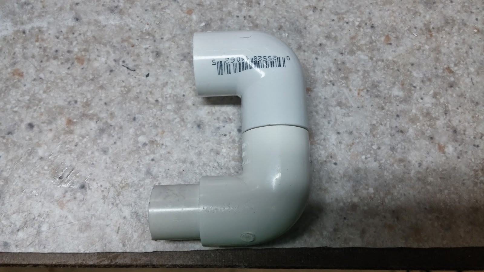
Take your two 1/2" PVC elbows and put them together like in the picture. Use the 1/2" PVC to connect them. It really should be self explanatory. You can glue or screw the pipes together if you want to.
Posted Image

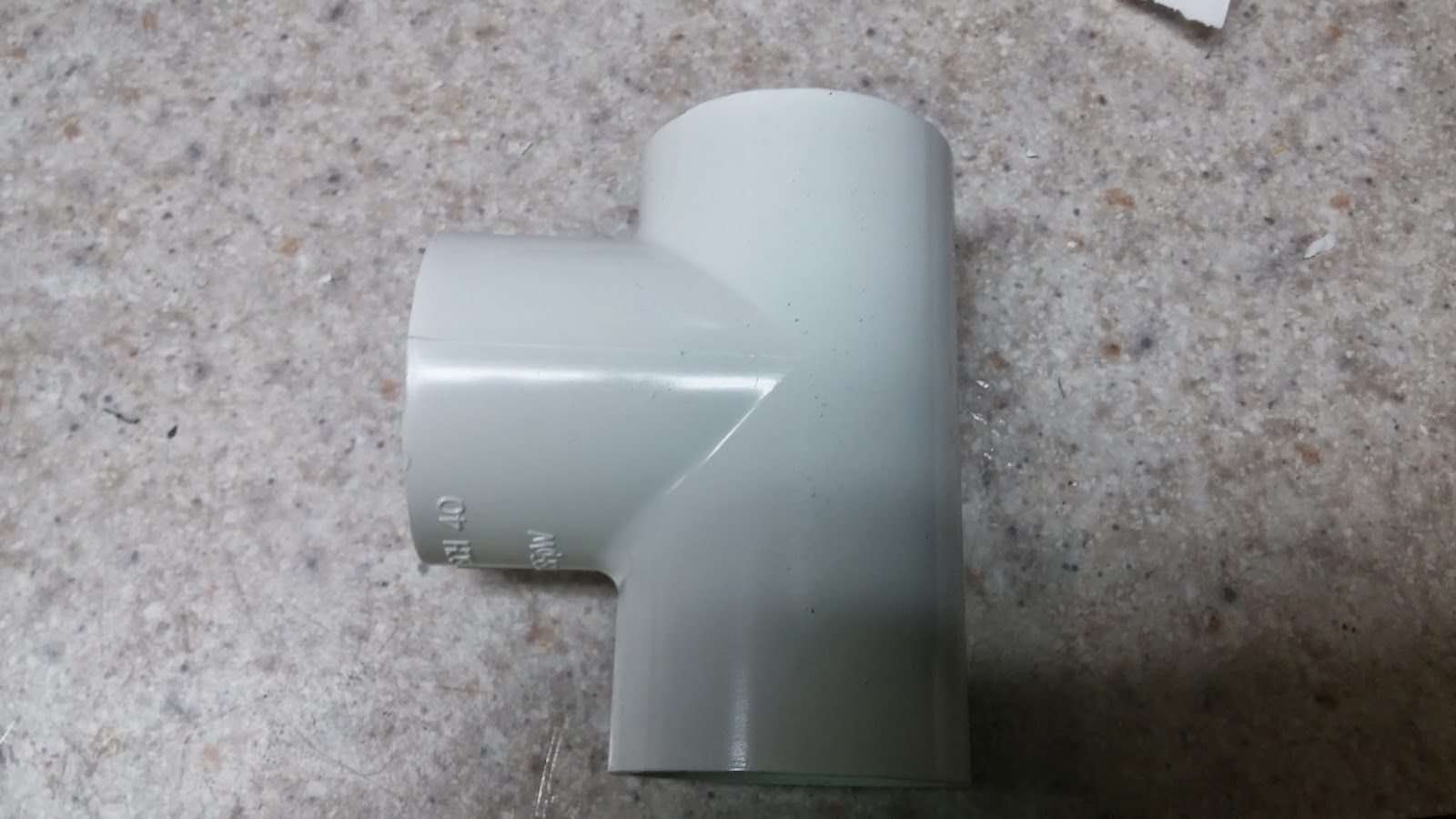
Take the 1.25" Tee and cut down the top a little bit until you can fit the elbows into it.
Posted Image

Slide the elbows into the tee with the PVC stub going through the side off the tee. Now put the tee onto the back of the blaster where the bushing is. Make sure the elbows get connected to the bushing.
Posted Image

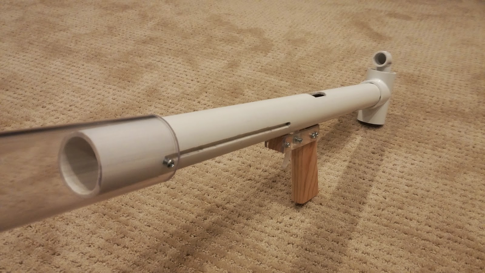
You are now finished with your blaster! As you can see, I chose to clean it up a bit. To do this, I rubbed rubbing alcohol on all of the PVC to get the sharpie off. I then took a sanding sponge to it and sanded down all of the words and barcodes on the pipe. This can take a little bit, but it makes the blaster look a lot better. If you are having problems with your barrel tilting down, find something that can be a spacer between the main body and the barrel and then glue it to the main body for the barrel to rest on. Barrel holders are a goos idea to have though. I have had no major problems with my barrel. Also, see below for another barrel holder option.
Posted Image

This blaster has over 7" of draw and if you do it right, it should have an almost perfect seal. Use your preferred barrel assembly (you want to use a hopper) and you will be wreckin' it on the field.
Posted Image
I really like this blaster design because it is very compact and it fires better than any of my other homemades including my rainbowpump.

Small Update
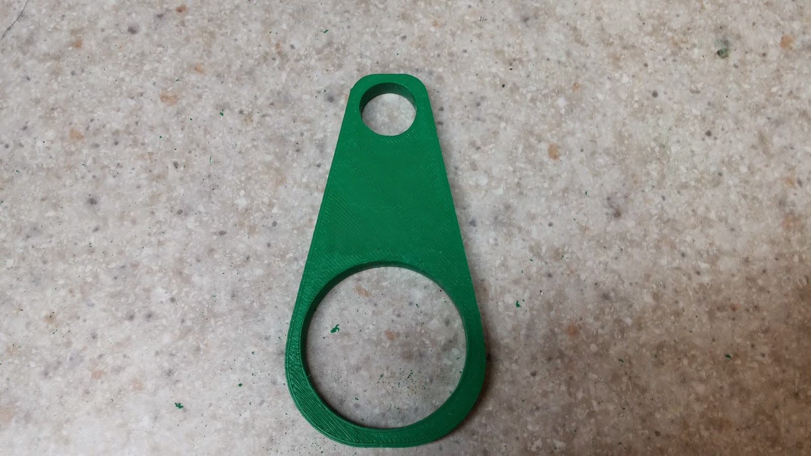
I decided to design a 3d printable barrel holder for this blaster because I felt like it needed one. The barrel holder makes the barrel way more stable and you don't have to constantly adjust the barrel.
Posted Image
Here is the link to the thingiverse page just incase you have 3d printer: Barrel Holder
Posted Image
I know a lot of people don't have 3d printers so that is why this is optional, even though it is really nice to have. If you want one of these and aren't able to print one, pm me and I will be able to get you one for a very low cost.

Extra things
Aeromech made a great writeup for areverse hopper to go with your reverse-firing blaster. I recommend checking it out, because I know I'll be building one.

Edited by Drev, 08 January 2015 - 11:10 AM.
  • 0
Check out my blog: Fly Nerf

#3 Exo

Exo

    Member

  • Members
  • 391 posts

Posted 26 May 2014 - 08:30 PM

All of that work, and you couldn't come up with a more ergonomic looking handle?

Good writeup! Great pics, too.
  • 0

#4 Drev

Drev

    Member

  • Members
  • 135 posts

Posted 26 May 2014 - 08:41 PM

All of that work, and you couldn't come up with a more ergonomic looking handle?

Good writeup! Great pics, too.


The handle is surprisingly comfy even though it doesn't look like it. Thanks.
  • 0
Check out my blog: Fly Nerf

#5 Thorn

Thorn

    Member

  • Members
  • 91 posts

Posted 26 May 2014 - 10:51 PM

Ryan201821 has some great templates for u-cup seals on his ESLT blaster build guide that you might be able to use. Also, I think you should include 1 1/2 in. thinwall PVC as an alternative to 2 in. polyester because it is cheaper if you can find it. Lastly, this might just be me, but I think you could improve it ergonomically and cosmetically by extending the front to flush with the pump grip, and making a horizontal foregrip similar to those used on many pumpsnaps. Other than that, the write up looks terrific and I think it is a very good americanized version of MIG's multiple orgasm. Good luck in the homemades contest.

Edited by Thorn, 26 May 2014 - 10:52 PM.

  • 0

#6 Birch

Birch

    Member

  • Members
  • 181 posts

Posted 27 May 2014 - 05:43 AM

You could also use 1" thinwall for the catch housing, just to make the catch not have to be downsized so much.
  • 0

It's like a Hurricane ate a Tornado and shat out a Monsoon!!


#7 Drev

Drev

    Member

  • Members
  • 135 posts

Posted 27 May 2014 - 08:29 AM

Ryan201821 has some great templates for u-cup seals on his ESLT blaster build guide that you might be able to use. Also, I think you should include 1 1/2 in. thinwall PVC as an alternative to 2 in. polyester because it is cheaper if you can find it. Lastly, this might just be me, but I think you could improve it ergonomically and cosmetically by extending the front to flush with the pump grip, and making a horizontal foregrip similar to those used on many pumpsnaps. Other than that, the write up looks terrific and I think it is a very good americanized version of MIG's multiple orgasm. Good luck in the homemades contest.

You could definitely make the front flush with the foregrip. It would look nice, but it would make assembling the blaster harder. I added 1.5" thinwall as an alternative, thanks for the suggestion. Adding a horizontal foregrip on the the pump would be very easy to do, but I chose not to do it on this model because I can wrap my hand all the way around the grip and it works very well for me. I might add a foregrip template though just incase someone wants one. Thanks.

You could also use 1" thinwall for the catch housing, just to make the catch not have to be downsized so much.

This could work, but there would be less room for the screws to thread into the pipe, making me worry about the stability of the catch and the pump grip. Thanks for the suggestion though.
  • 0
Check out my blog: Fly Nerf

#8 He Who Mods

He Who Mods

    Member

  • Members
  • 108 posts

Posted 27 May 2014 - 11:00 AM

Great write-up. I remember seeing this on youtube almost a year ago and now it is finally here!
  • 0

#9 Thorn

Thorn

    Member

  • Members
  • 91 posts

Posted 27 May 2014 - 11:43 AM

Great write-up. I remember seeing this on youtube almost a year ago and now it is finally here!

We might need Drev to confirm this, but if you read his blog, I'm pretty sure this is a newer model based on his previous bullpup.

Edited by Thorn, 27 May 2014 - 11:44 AM.
  • 0

#10 makeitgo

makeitgo

    Member

  • Members
  • 216 posts

Posted 27 May 2014 - 12:49 PM

...Well this looks familiar....

If you modify your trigger, make it beefier and add a slope to the part that trips the catch, it would be slam-fire capable. Do you find the stock length a little too long once you include the reach of the priming grip? Other than that, I like it.

For anyone unfamiliar with this bull-pup configuration, a big advantage is that the hopper rests behind your head. This way, it doesn't obscure your view/aim at all.

Thorn - "Ameriagasm"!

Edited by makeitgo, 27 May 2014 - 01:04 PM.
  • 0
"...he is one speedy bastard." ~ Cheyner

#11 Drev

Drev

    Member

  • Members
  • 135 posts

Posted 27 May 2014 - 02:49 PM

We might need Drev to confirm this, but if you read his blog, I'm pretty sure this is a newer model based on his previous bullpup.
I made the video a while ago for my first version. This one is the newer model and I plan to make even more models.

...Well this looks familiar....

If you modify your trigger, make it beefier and add a slope to the part that trips the catch, it would be slam-fire capable. Do you find the stock length a little too long once you include the reach of the priming grip? Other than that, I like it.

For anyone unfamiliar with this bull-pup configuration, a big advantage is that the hopper rests behind your head. This way, it doesn't obscure your view/aim at all.

Thorn - "Ameriagasm"!

I was actually planning on making it slam-fire capable eventually. The stock length definitely is long, but I don't find it too long. I like longer stocks and this stock makes my rainbowpump stock feel uncomfortable. The stock could feel too long for some people, though everyone that has used this so far hasn't had a problem. I plan on making another version of this over the summer that will probably use a sliding trigger and have a shorter stock, making it shorter in general. For this version, I just wanted it to see if I could make it have a normal rainbow handle because I'm used to making those. Thanks for the compliments, it means a lot coming from my inspiration for this project.

And yes, having the hopper behind your head is one of the best things ever. Ameriagasm seems like an awesome name!

Edited by Drev, 27 May 2014 - 02:53 PM.

  • 0
Check out my blog: Fly Nerf

#12 makeitgo

makeitgo

    Member

  • Members
  • 216 posts

Posted 04 June 2014 - 12:25 PM

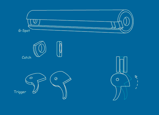
If you're comfortable with the stock length, you don't need to make a sliding trigger to make it slam-fire capable.

Posted Image

Hopefully, the drawing is clear enough.

The trigger has a specific slope that allows the catch to be tripped when the trigger is in the pulled position. Plus, this design also solves the problem of not being able to fire it 'one' handed. A sliding trigger is great but you need two hands to fire it. One to pull the trigger and the other to hold the G-Spot in the forward position. The above illustration resolves that specific problem.

Edited by makeitgo, 04 June 2014 - 12:26 PM.

  • 0
"...he is one speedy bastard." ~ Cheyner

#13 Drev

Drev

    Member

  • Members
  • 135 posts

Posted 04 June 2014 - 01:40 PM

Awesome trigger design thanks for making it. I'm going to make another one of these soon and make the extra cuts so that I can have slam fire using that design. Also, the sliding trigger was just to make it shorter, not for slam fire. That way everything can be pushed back and the handle won't interfere with the plunger tube. I might just stick with this design now and improve upon it because firing it with one hand is really nice and sliding triggers are a pain.

Edited by Drev, 04 June 2014 - 01:42 PM.

  • 0
Check out my blog: Fly Nerf

#14 MacZyver

MacZyver

    Member

  • Members
  • 2 posts

Posted 02 August 2014 - 08:59 PM

Out of curiosity. How does the priming mechanism work?

Is it similar to this one? http://nerfhaven.com...showtopic=23750

Apologies for not shrinking the link


To the mods: sorry for bumping this topic

Edited by MacZyver, 02 August 2014 - 11:01 PM.

  • 0
There's (almost) nothing you can't fix with Duct Tape.

#15 Zorns Lemma

Zorns Lemma

    Sir Scrt

  • Moderators
  • 1,277 posts

Posted 03 August 2014 - 06:01 PM

Out of curiosity. How does the priming mechanism work?

Is it similar to this one? http://nerfhaven.com...showtopic=23750

Apologies for not shrinking the link

This one is a version of that original idea. They are essentially the same blaster, as the differences are choices in execution rather than design.

Edited by Zorns Lemma, 03 August 2014 - 06:02 PM.

  • 0
"In short, the same knowledge that underlies the ability to produce correct judgement is also the knowledge that underlies the ability to recognize correct judgement. To lack the former is to be deficient in the latter."
Kruger and Dunning (1999)


Also tagged with one or more of these keywords: bullpup, homemade, writeup, rainbow, spring

1 user(s) are reading this topic

0 members, 1 guests, 0 anonymous users