Preface
As I have only recently began building homemade Nerf blasters, it is fitting that I share my first-time experiences with those in a similar position that may have less experience or know-how. This write-up marks the culmination of the lessons learned over two blasters before it, and represents an entry level Rainbow-pump blaster with a modified setup.
Additionally, this homemade guide does not necessitate the use of a drill press, hole saw, or mill. This write-up serves to prove that a new homemade builder can create a durable and reliable blaster using only hand tools. That being said, it is not easy, and those new to homemades should still proceed with caution. I have ample experience with crafting and tinkering, and I was able to figure this out pretty easily. Don't jump in headfirst. I try to point out my reasons behind doing things the way I do herein, and I can only recommend proceeding with a firm understanding of the system.
Credits to:
Ryan McNumbers for his Original Rainbowpump writeup
Stark and the Rainbow clan for the brilliant rainbow catch design
Daniel Beaver for hosting the catch templates.
Strap on those safety goggles and let’s begin. All descriptions shall be located BELOW their reference photo for this write-up.
Raw Materials
McMaster-Carr:
49035K86: Schedule 40 Clear PVC Pipe 1.25”
9562K46: Rotary Shaft Ring Seal, 0.95” to 1.07”
8541K18: Black Nylon Rod, 0.5”
9245K51: 2" OD Clear PETG
9637K26: [k26] Compression Spring, 11” Length
8574K28: Polycarbonate Sheet, 12”x12”x0.25”
96565K36: Catch Spring
4880K636: ½” PVC Wye
Ace Hardware:
1 Box Pan Head 6-32 Machine Screw, 3/4” Length
1 Box Flat Phillips 6-32 Machine Screws, ½” Length
1x Pan Head 8-32 Machine Screw, 1-½” Length
1x Pan Head 8-32 Machine Screw, 1-1/4” Length
1x #10 Washer
1 ft of 2” PVC Pipe
1x 1-1/4” PVC Tee Coupler
2 ft of ½” PVC Pipe
1x ½” PVC Ball Valve
2x 1” to ½” Bushing
1-1/2 ft ½” CPVC Pipe
1/2" of 1/2" CPVC foam insulator tubing
1x Tub of Silicone Grease
1x Tube Lithium Grease
Home Depot:
Plumber’s Goop (Couldn’t find it in Ace)
Walmart:
2 Cutting Boards
Packaging Tape
Craft Foam
Zumiez:
Skateboard Tape (optional, but it’s only $5 for a 4 ft sheet)
Tools
Safety Goggles
Safety Gloves; you’re laughing now but they’re damn helpful.
Hacksaw
Course File
Less-Course File
Rat-Tail File
Phillips Head Screwdriver
Tapping Wrench
6-32 Tap
8-32 Tap
Electric Drill
Set of Drill Bits
Countersink
Sandpaper
Gorilla Tape
Sharpie
Printer
Stick glue
Hot glue gun
Tiny bit of blu-tac
Table Vice
The Genesis of the Design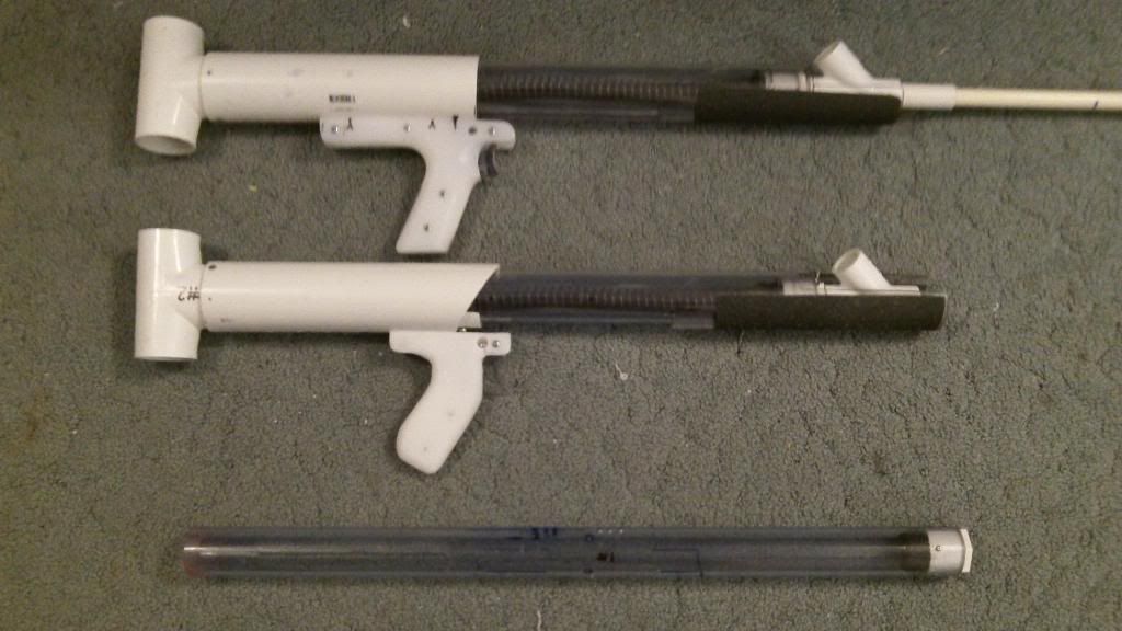
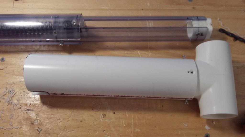
This is my first series of Homemade blasters, as the figure above illustrates. From bottom to top, the first, the second, and the third blaster in the series. This write-up focuses on the third, which takes the lesson learned from the previous two designs.
General Dimensions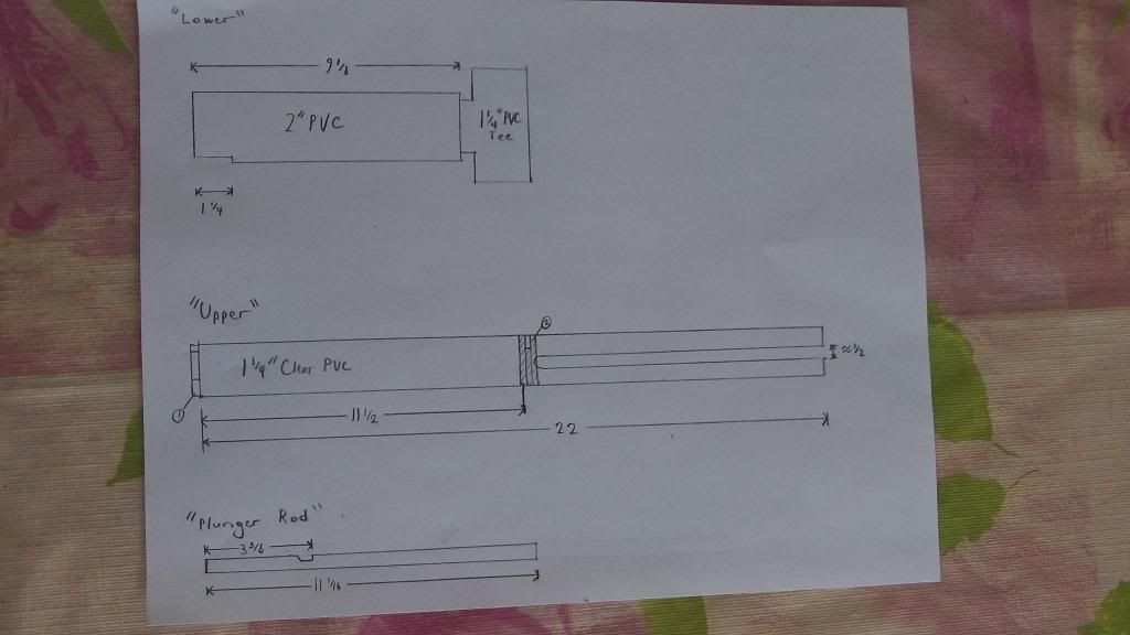
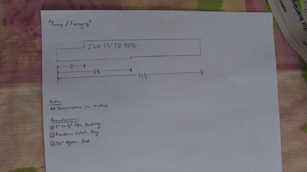
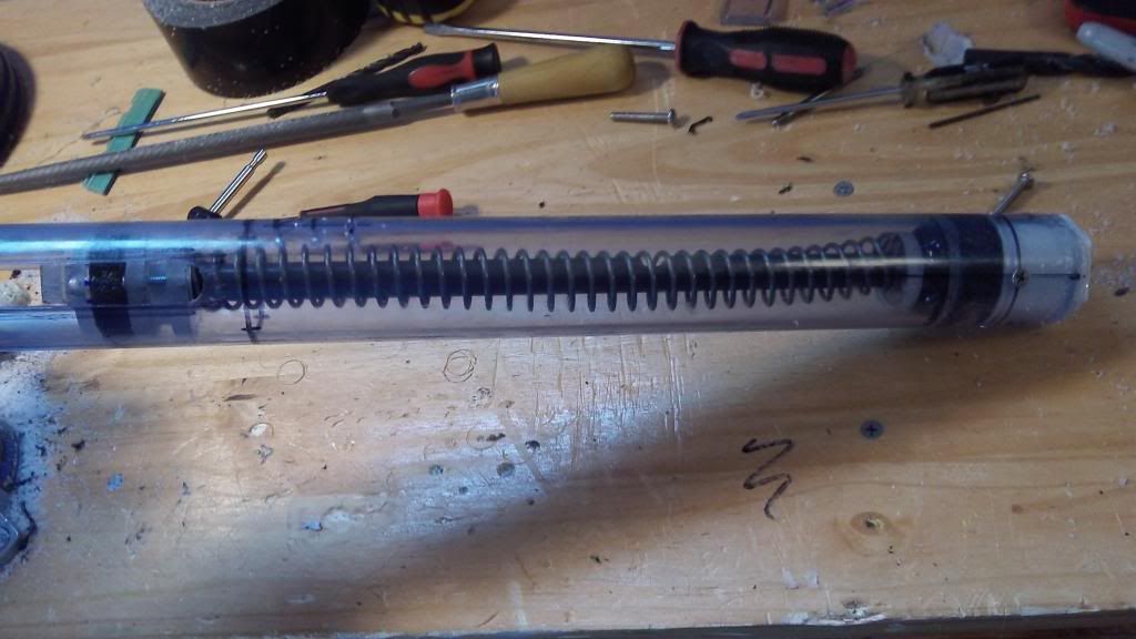
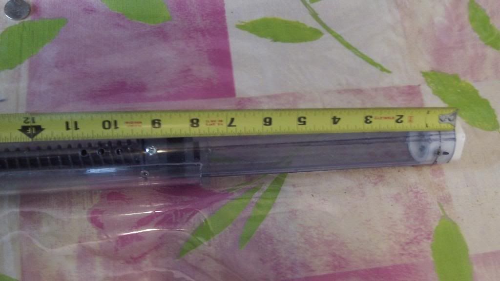
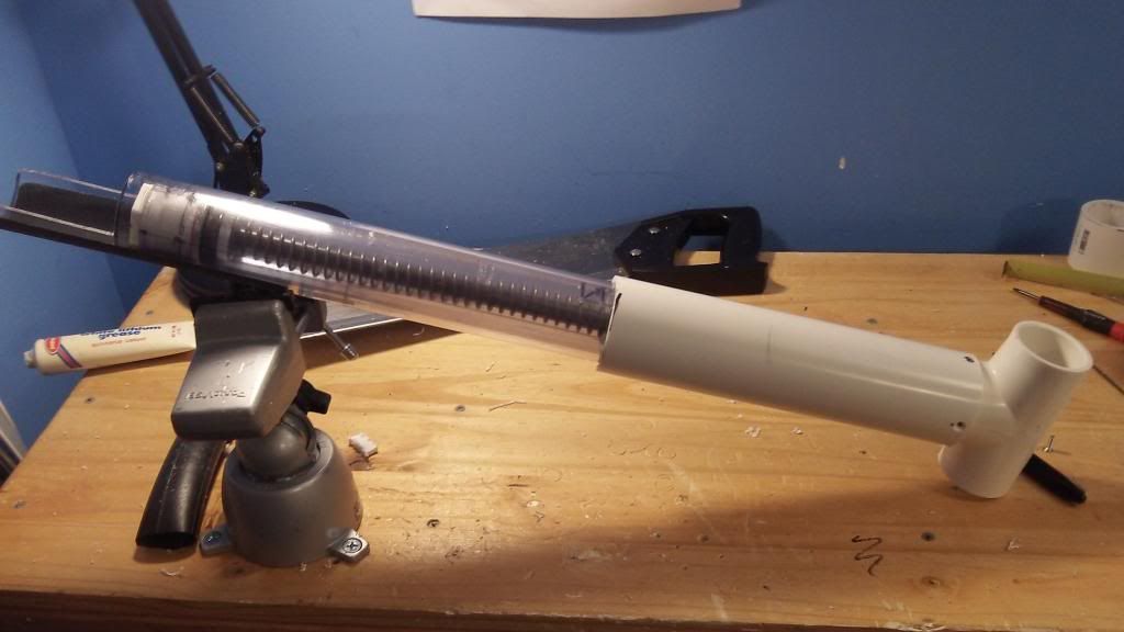
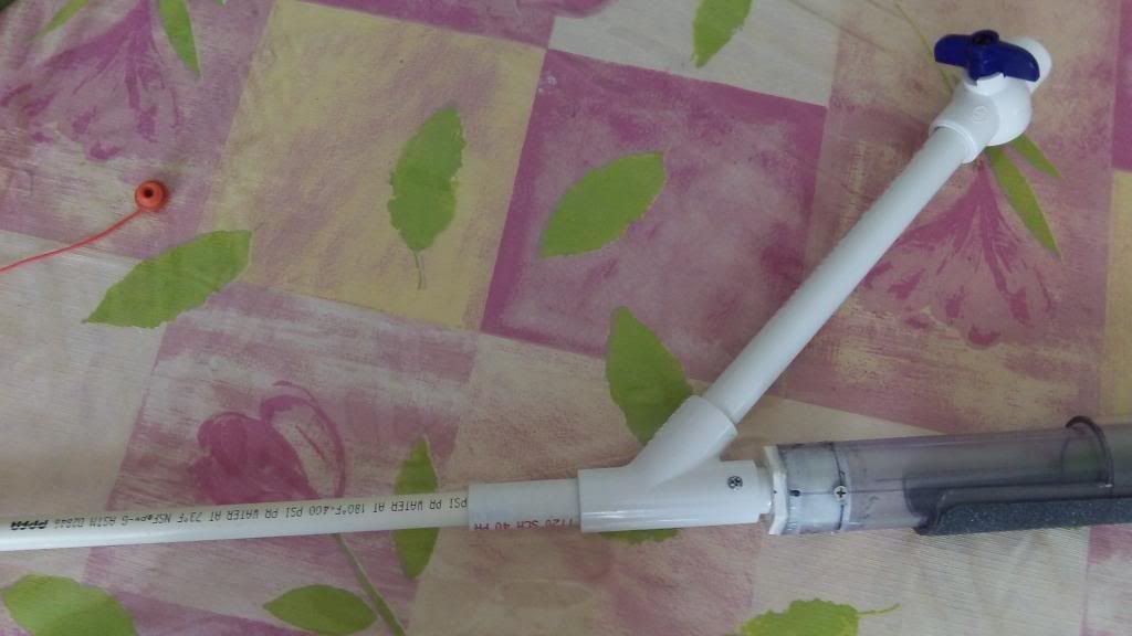
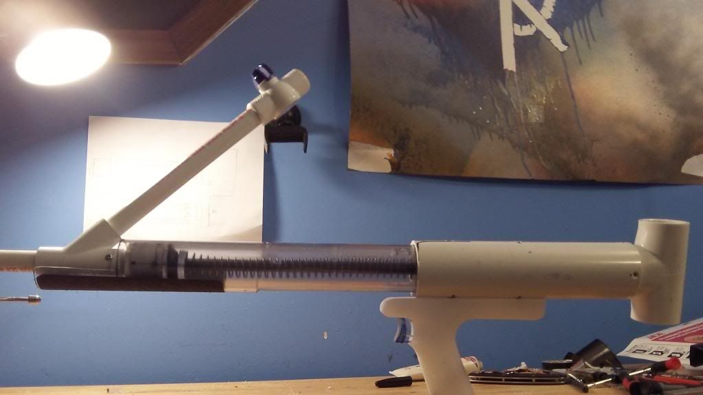
Complex CAD drawings can be intimidating. Here are some simple drawings that outline the lengths of each large piece. Mechanically, I separated the Rainbow Pump into three sections: The “upper,” “lower,” and “pump,” and the plunger rod to reference later in the writeup. This design actually deviates from the original Rainbowpump design, but allows for new plunger tube assemblies, or “uppers” in this case, to be swapped out easily without having to fabricate a new handle.
Adhere the Bushing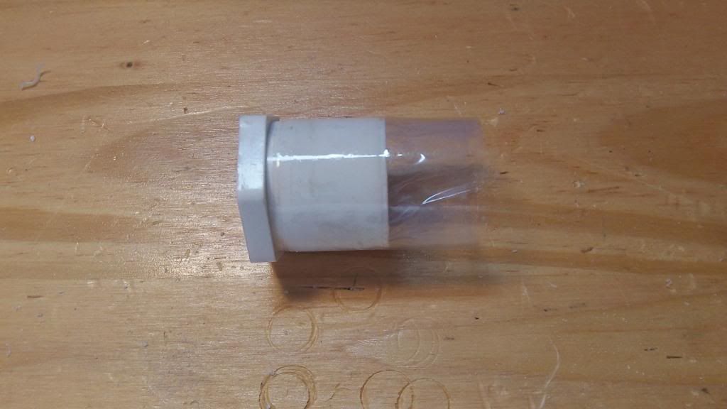
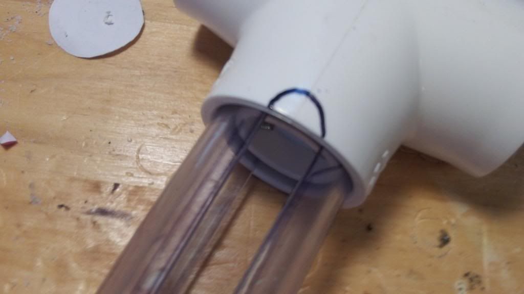
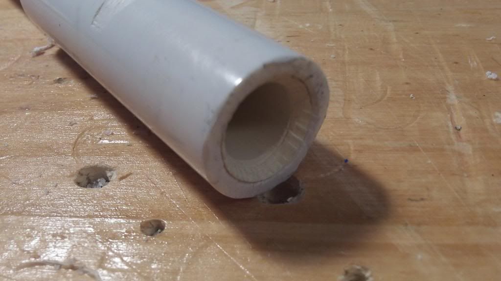
Wrap both of the bushings in plumber’s tape until the bushings fit tightly in the 1-1/4” Clear PVC Pipe. Cut off the excess tape from each bushing. Set one aside.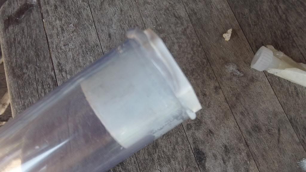
Apply Plumber's Goop around the outer diameter of the Bushing and press it in there firmly. Be sure to perform this step outside. There's toluene in that shit.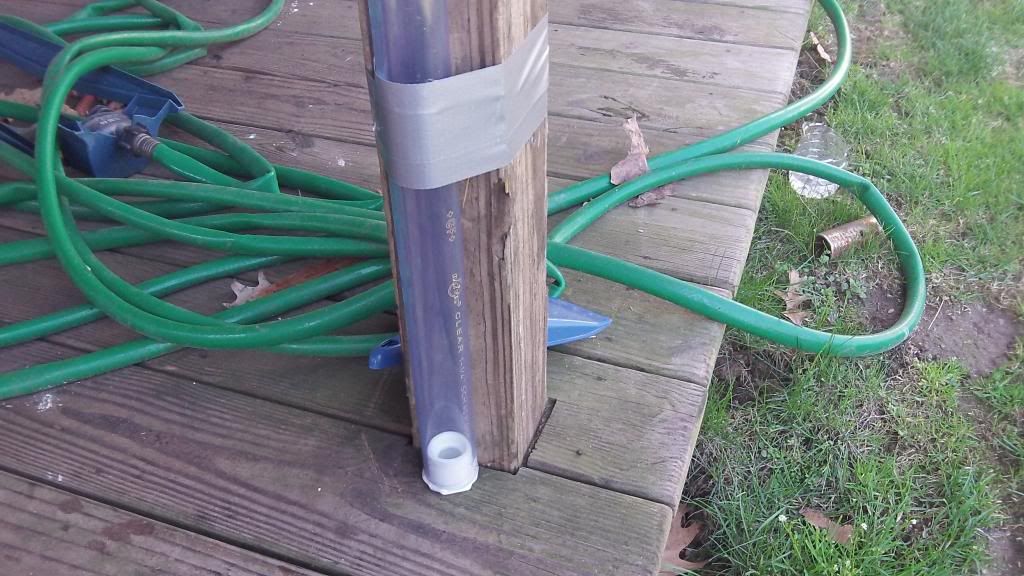
This is how I allow the Goop to cure. I let it rest vertically for about 12 to 24 hours, to ensure that the goop doesn't drip out of one side. Maybe superstitious, but in any case keep the tube outside until the goop is fully cured.
The Rainbow Catch
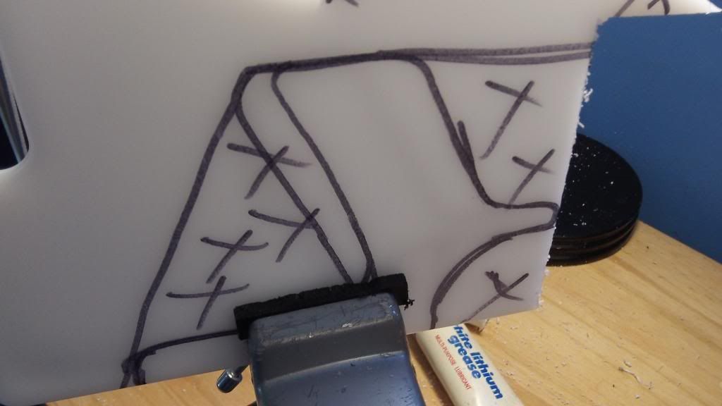
Here are the templates for the rainbow catch, hosted by Daniel Beaver. Print out 2 copies. Make sure you click "actual size" and not "fit to page" when you print, otherwise your templates will be too small.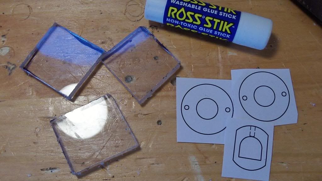
Cut out the templates, and a few squares of polycarbonate...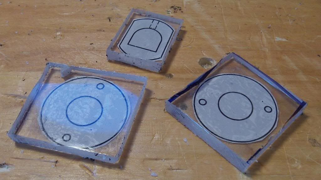
and glue them onto each piece using super sticky stick glue.
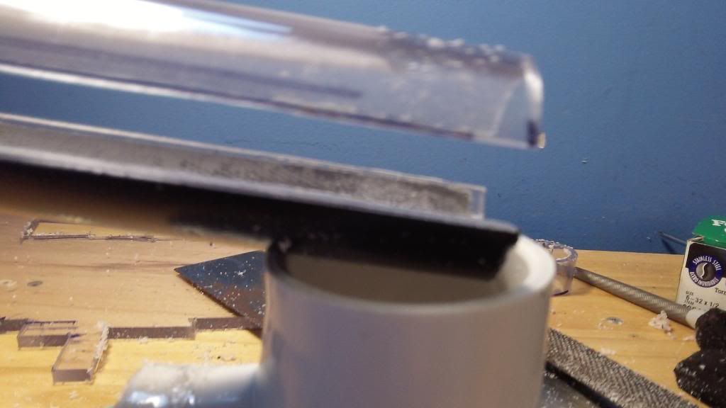
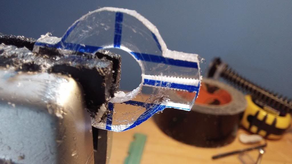
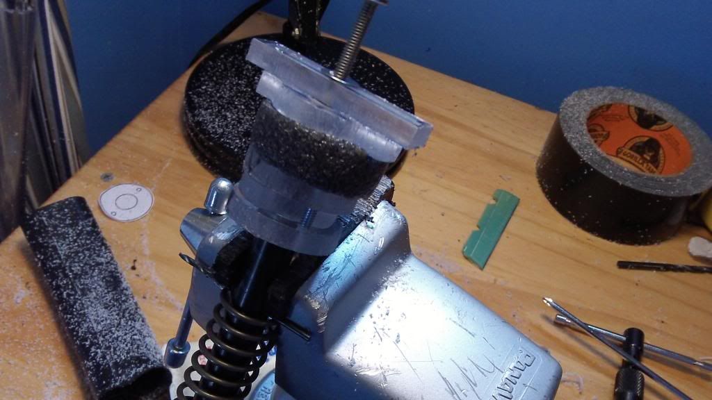
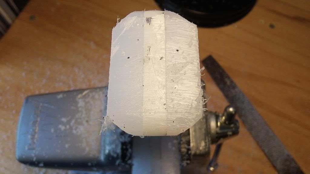
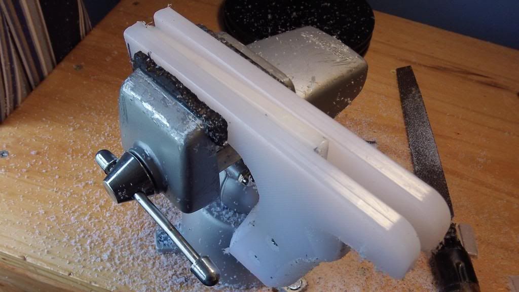
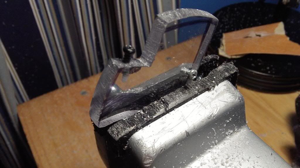
Stick it in your vice, and use your course file to trim each side right up the the black line of the outer circle on the template, but do not file away any of the black line itself, this actually represents material that is supposed to remain intact.
Now file down each corner to form an octagon, again trimming right up to the black line.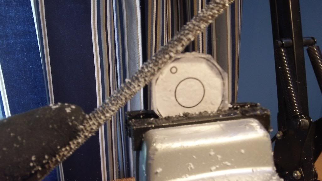
Use your file to blend together two of the adjacent sides.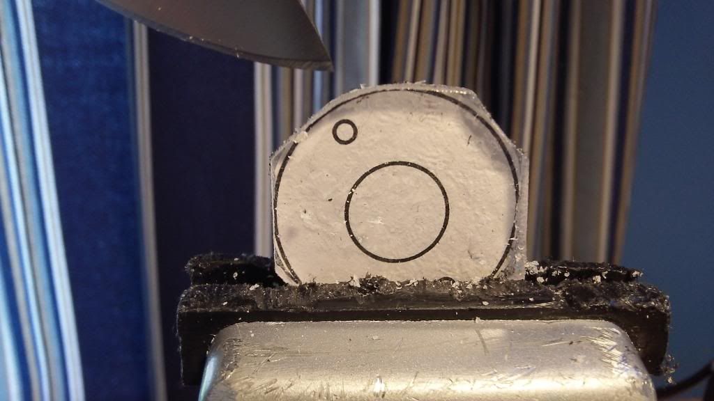
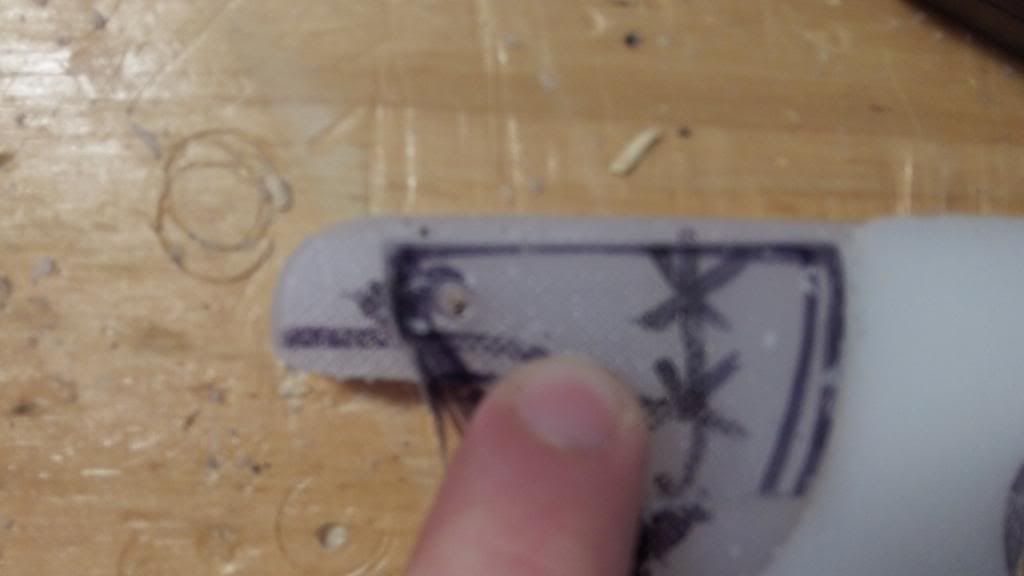
The knife is pointing to the blended side. Repeat this blending on all corners to create a circular part.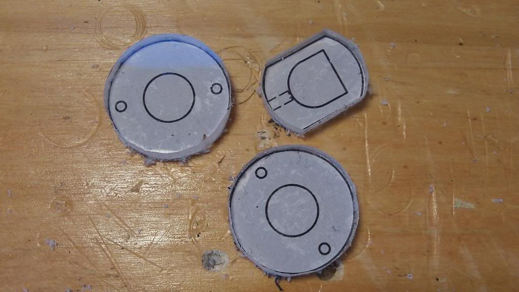
Repeat this process of filing flats, then blending them together to all rainbow catch parts.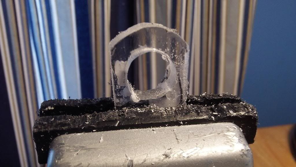
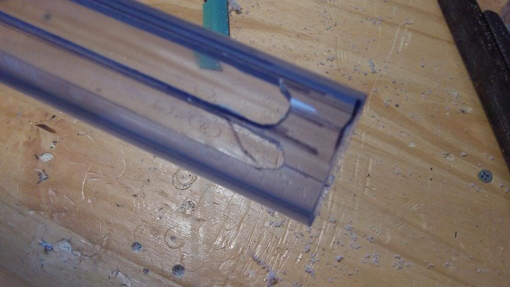
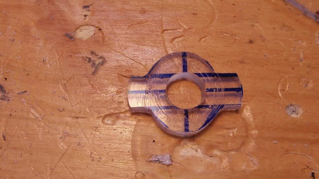
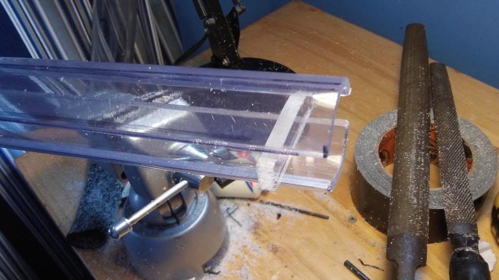
To create the hole in the catch plate, first drill out a 1/2 inch hole in the center of the plate. If the drill torques the part out of the vice, drill the largest diameter you can, and then ream out the hole to 1/2 inch diameter with your rat tail file. The bottom corners should be square. To create this effect, drill a small diameter hole, maybe 1/16 or 3/32 just inside of those corners. Then, use a knife to carve out the flats on the two walls and the floor of the catch plate.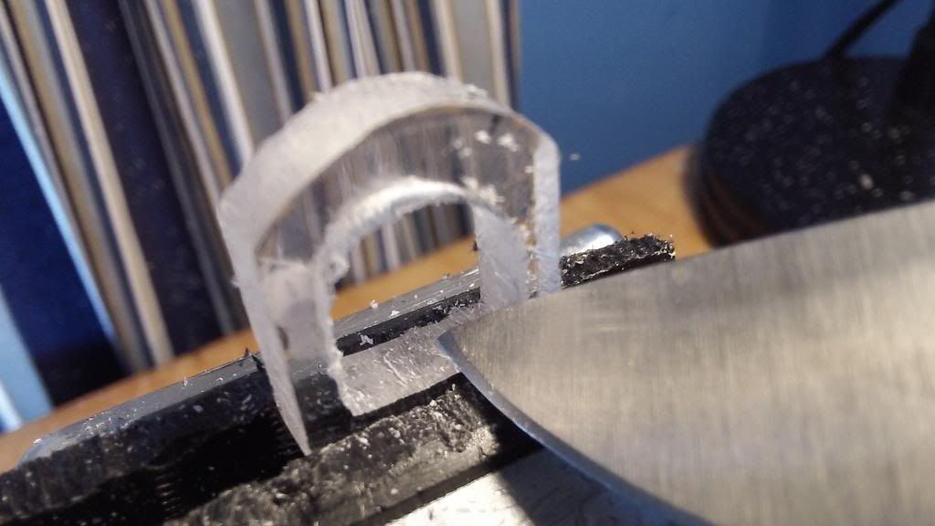
Now you have the desired shape. Drill out the outer two catch plates, using a 7/32" drill bit for the outer holes. The center hole should also be 1/2 inch in diameter. Drill through and ream out if necessary.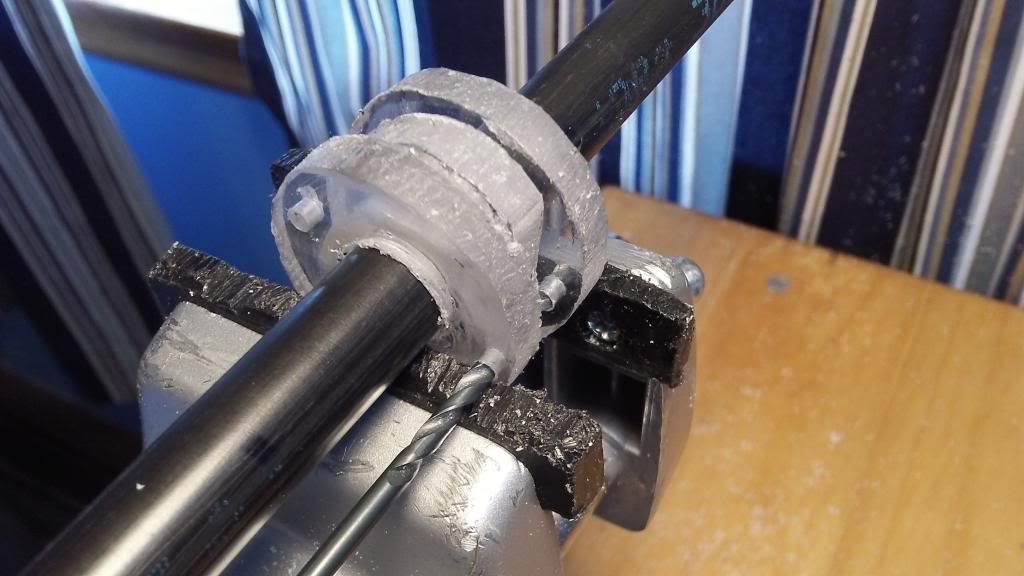
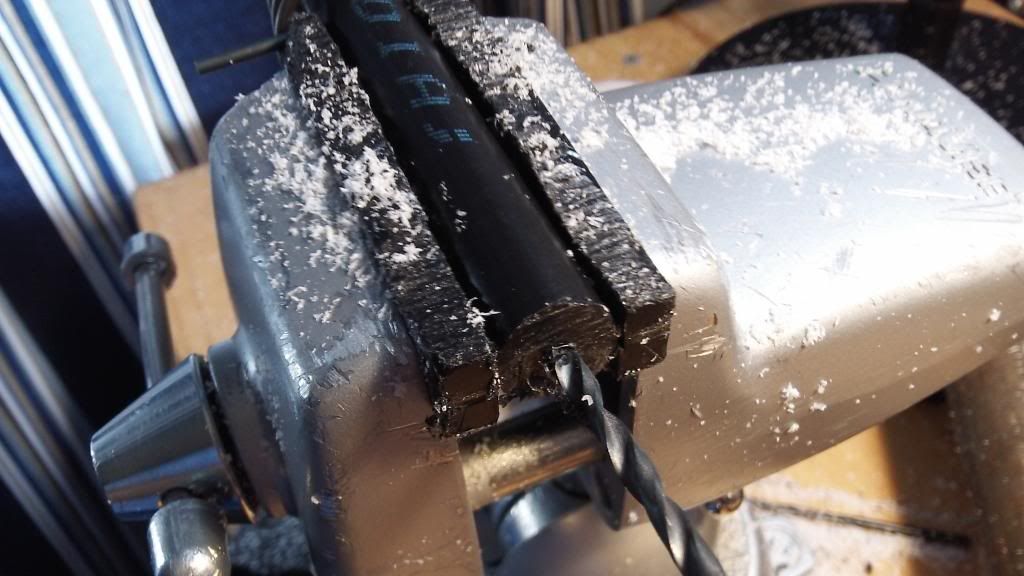
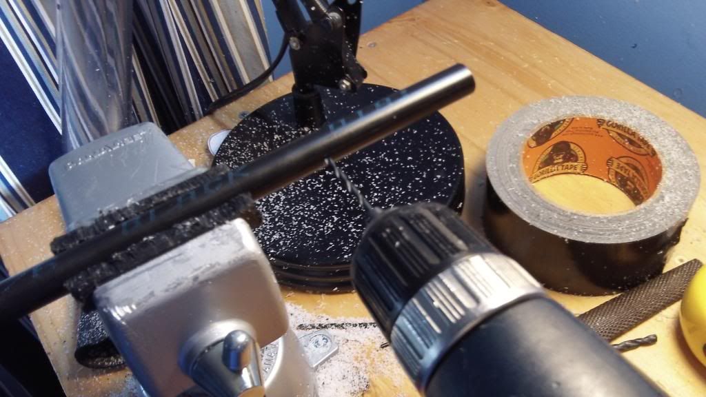
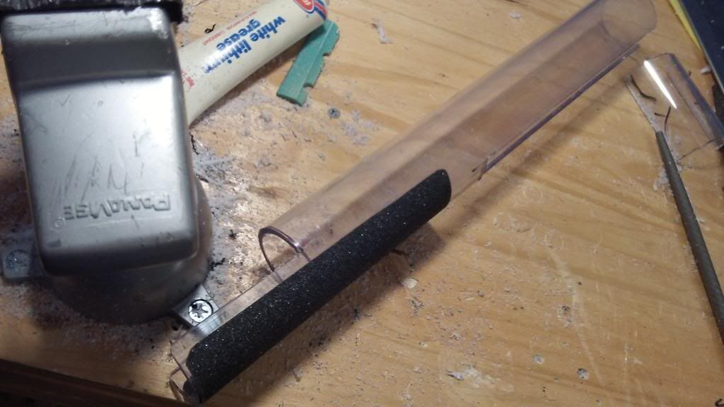
Use a section of 1/2" Nylon rod to keep the outer holes of the outer two catch plates in alignment while drilling.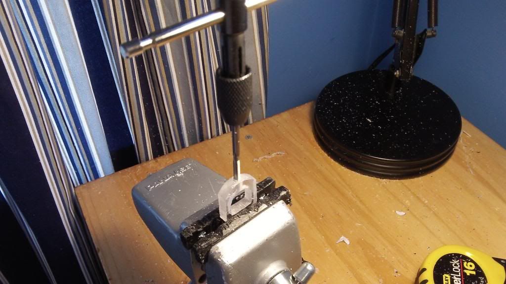
Drill and tap the bottom of the inner catch plate, first with a 7/32" drill bit, then a 6-32 tap.
TO TAP: Place a bit of lithium grease on the end of the tapping tool. Once the teeth of the tap have gripped the material, screw one turn forward, then one half turn back. One turn forward, half turn back. Repeat until the desired thread depth is achieved. The grease acts as a means of heat dissipation and ensures smooth entry. The backing out after each turn allows the built-up material inside the hole to clear out. I've broken a tap before by not following these rules.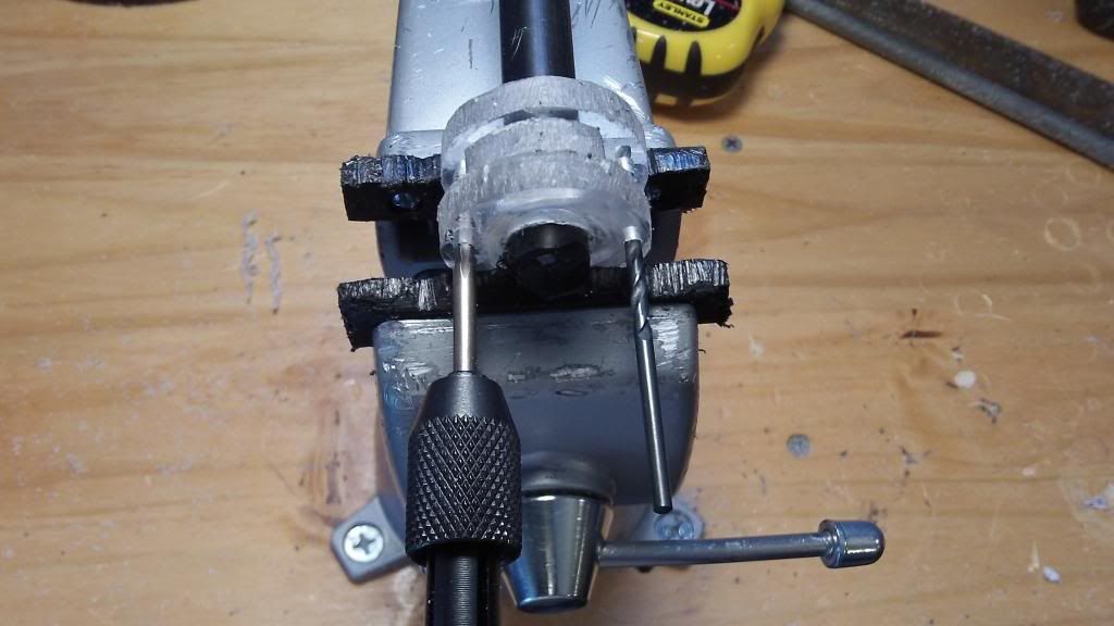
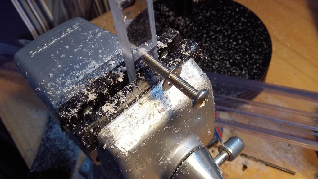
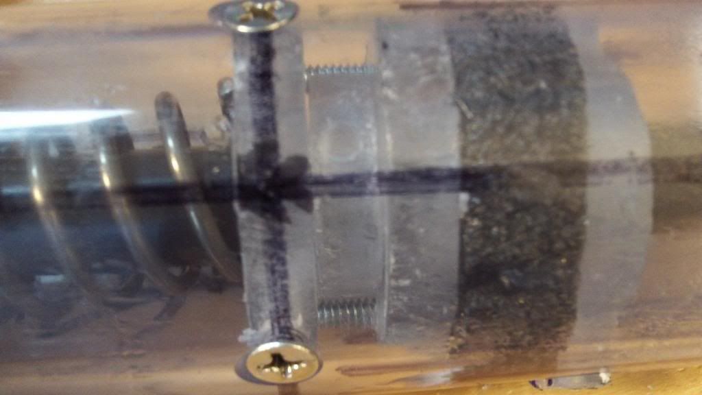
After drilling both holes, leave the bit in one of the holes, and tap with the entire assembly in a vice. This will ensure the threads line up once the catch assembly is put together post-fabrication. Tap using the 6-32 tapping bit.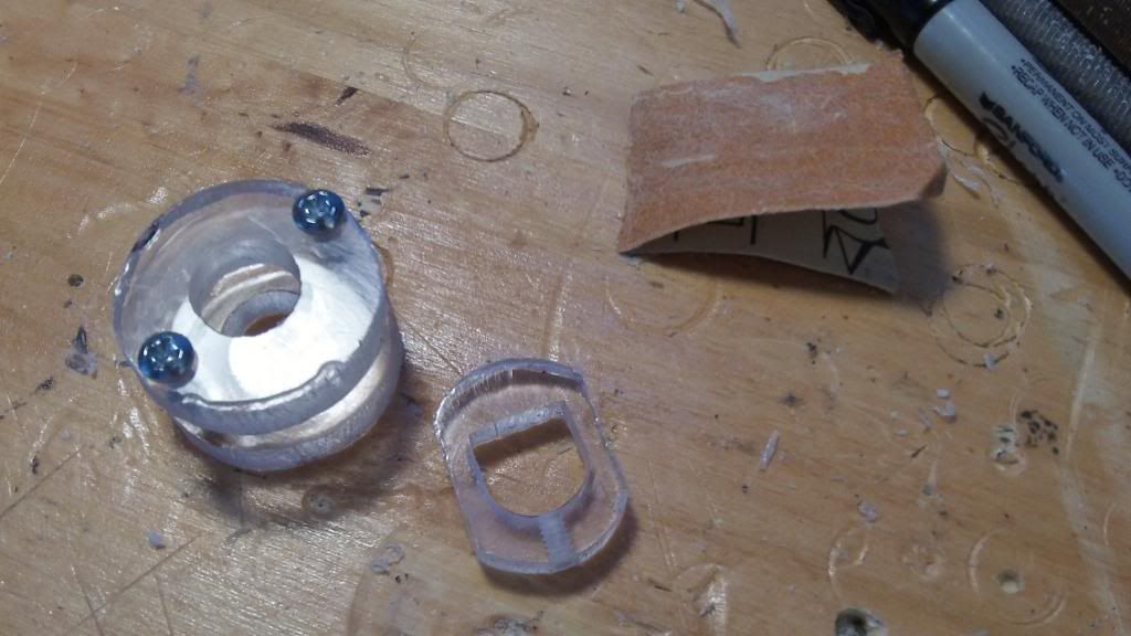
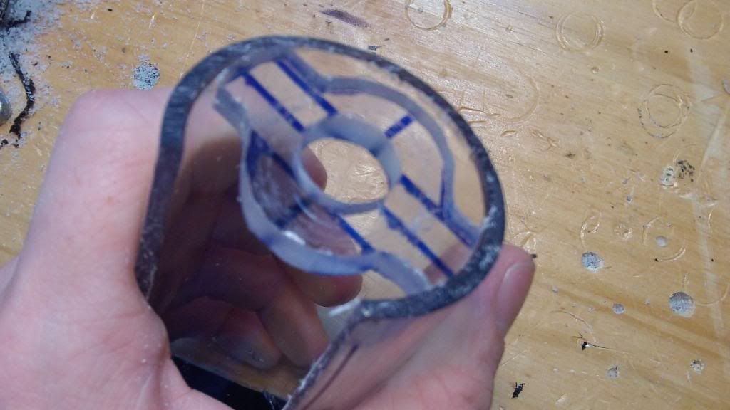
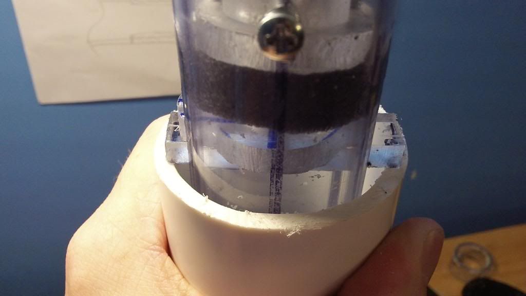
Screw together the two outer catches. Test fit in a piece of 1-1/4" PVC. That's the catch.
Plunger Assembly, Part 1
There are many plunger head designs out there, but I could not find just a "skirt seal" plunger head. Alas, I found it necessary to improvise. This plunger head yields a perfect or damn-near perfect air seal.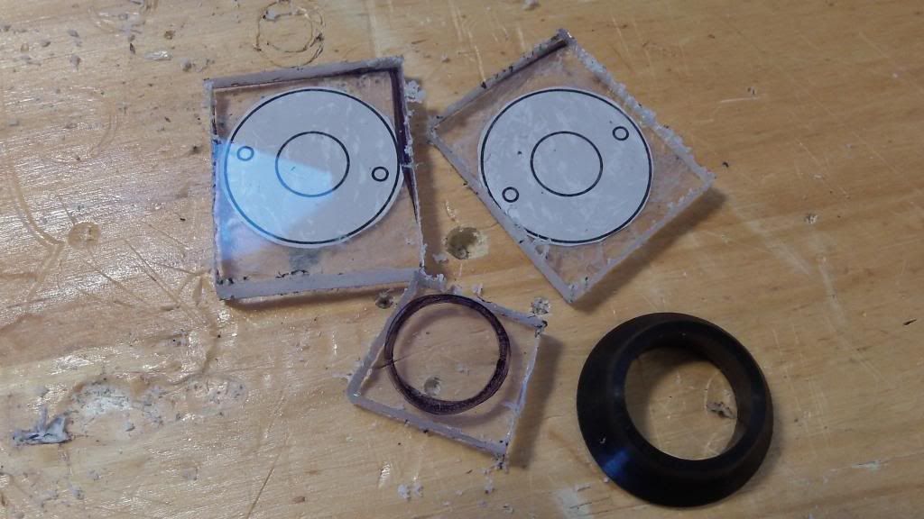
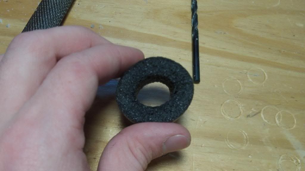
Take the second Rainbow catch template, and set up the two outer catch plates onto two pieces of polycarbonate. We are only using these templates for the outer circles this time. For the third piece of polycarbonate, trace around the inside of the rubber ring seal with your sharpie.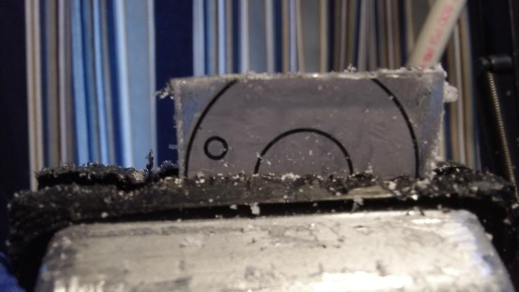
This time, file slightly inside of the lines, using the same technique as the catch to file flats, then blend. Repeat for the other outer catch template. The smaller traced template should fit snuggly inside the ring seal.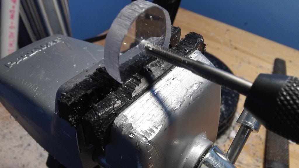
Drill and tap using a 1/8" drill bit followed by the 8-32 tapping bit through each polycarbonate disc. Use the template to center the hole on the larger two disks, and eyeball the center of the small one; the best way to do this, I've found, is to center a water bottle cap underneath this piece, and make a center mark based on the central divet of the bottle cap.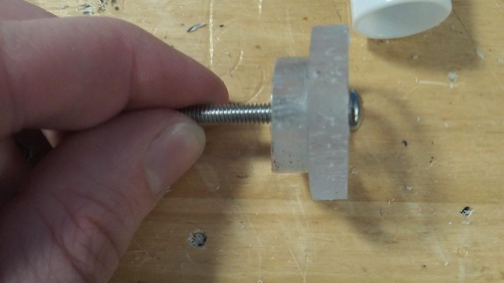
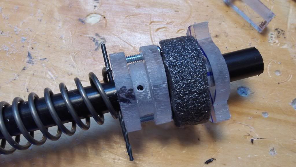
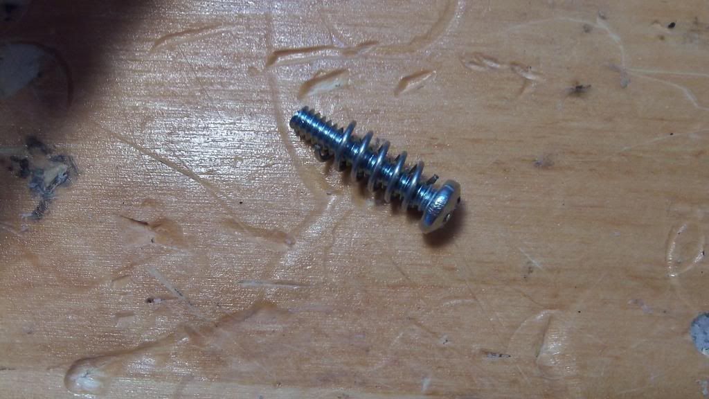
Screw on a large disk then the small disk onto the longer 8-32 screw. This larger diameter screw is used due to higher stresses that the plunger head encounters.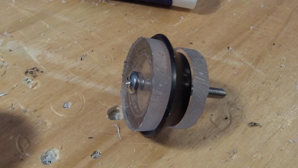
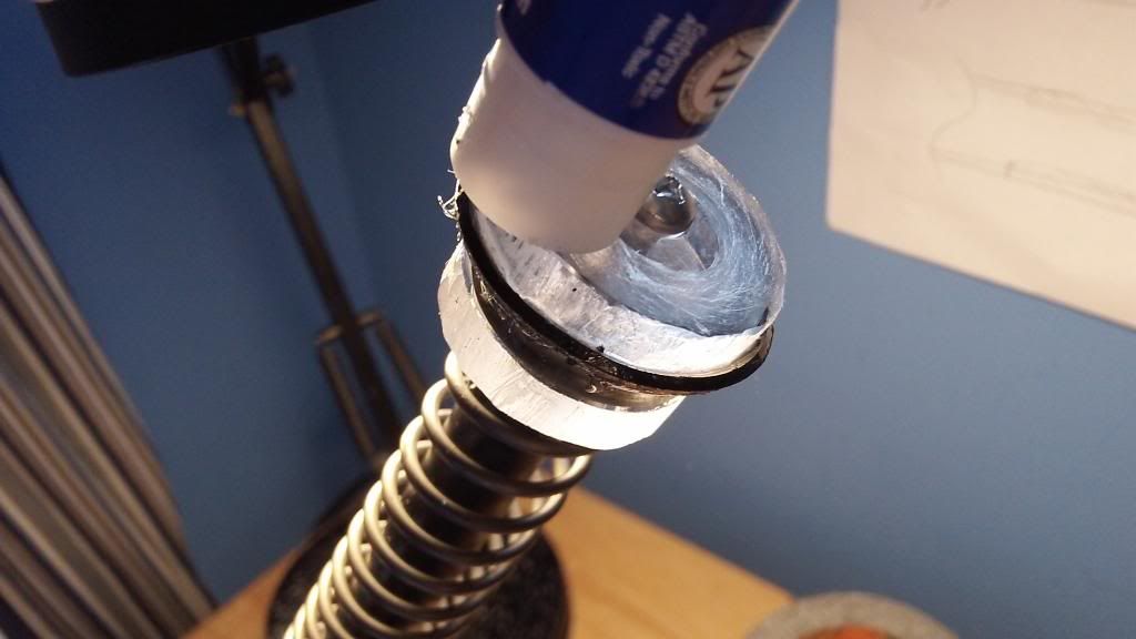
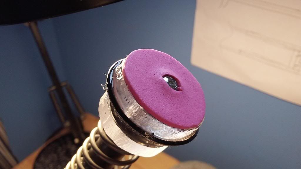
Slip on the ring seal, and then screw on the final large disk locking everything in place. There should be a firm force pressing the seal together from the outer two disks. The interior disk is used to keep the seal centered.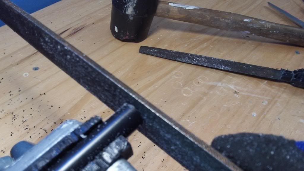
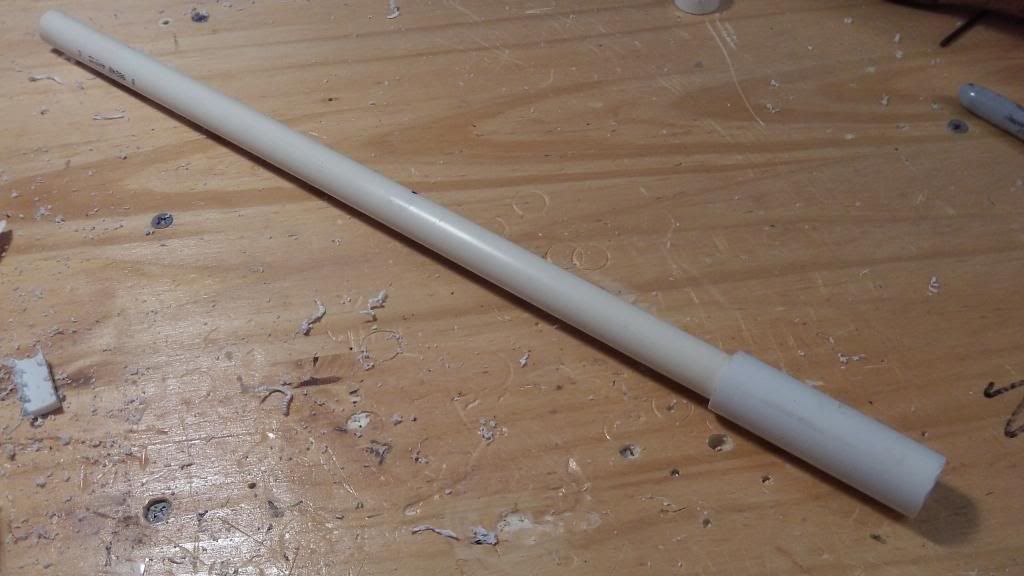
Cut the Nylon rod down to 11-1/16". File off both ends with the fine file, ensuring a flat surface on each end of the rod.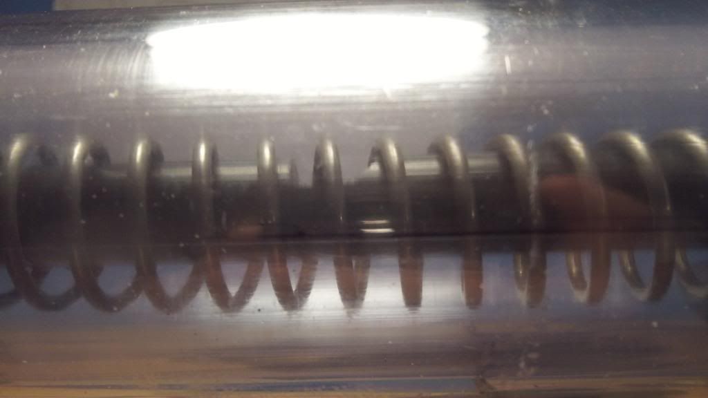
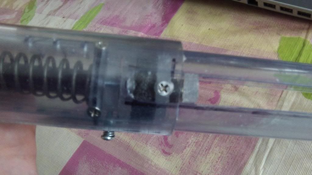
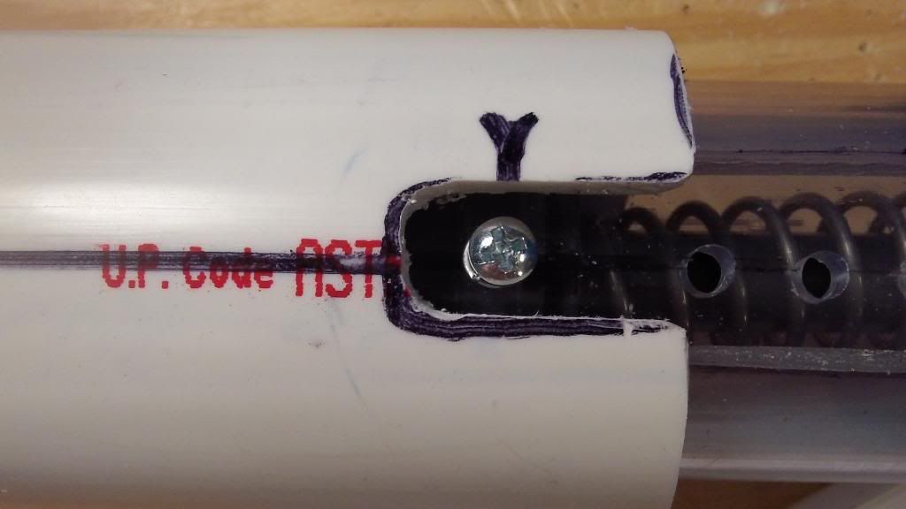
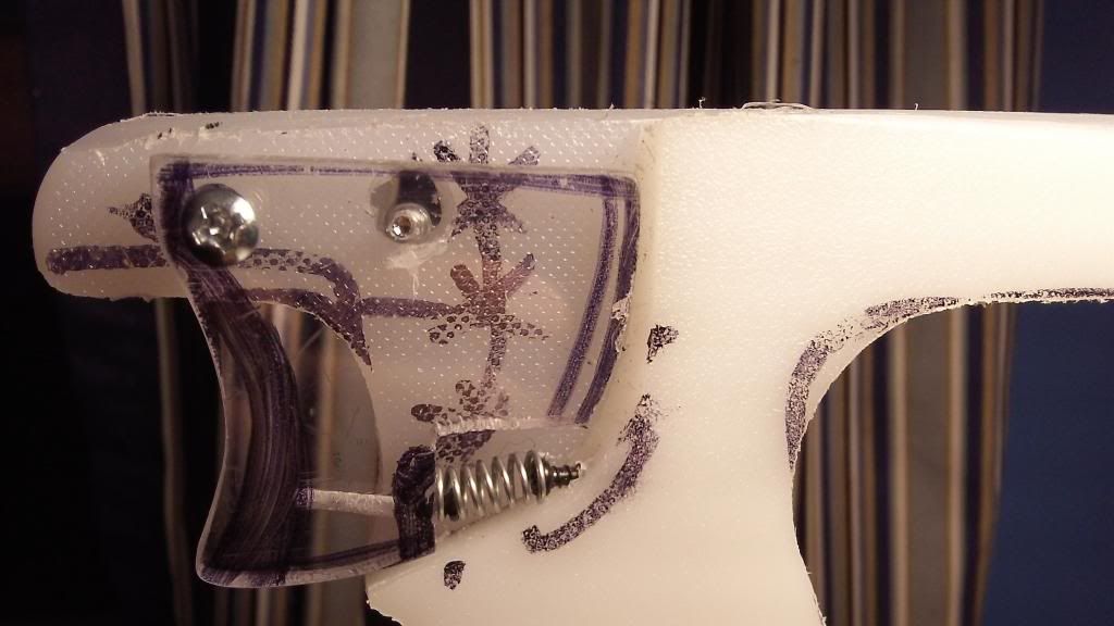
This is the catch notch in the fully assembled blaster. The front is sloped at 45 degrees, and the rear wall is vertical. When the blaster is primed, the spring exerts a force forward on the plunger assembly. the catch is "caught" in that little notch, and basically gets in the way of the plunger rod, stopping it from moving forward. When the trigger is pressed, the catch is pushed upwards and out of the way of the plunger notch, allowing the plunger assembly to slam forward with the force of a thousand laser beams. The notch itself should be about 1/3 of the diameter of the rod.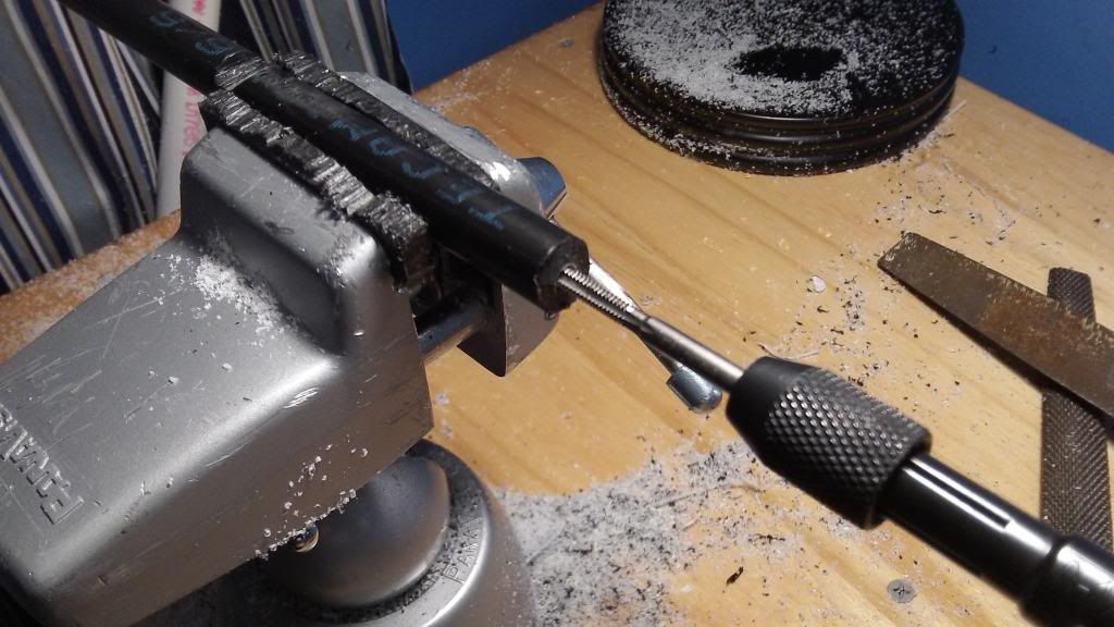
Drill one end about 1 inch deep with a 1/8" drill bit, then tap with the 8-32 tap.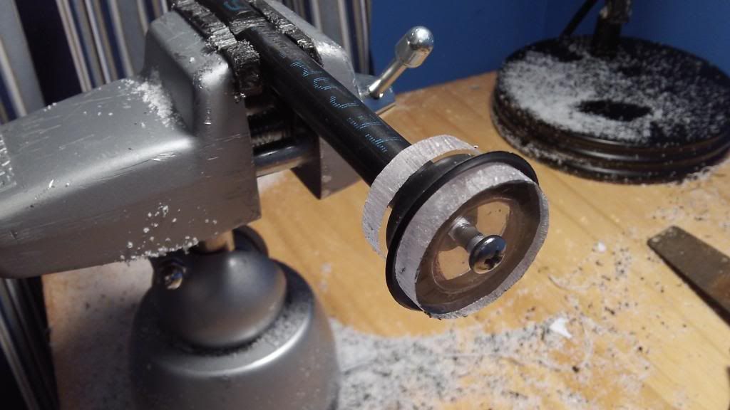
Screw your plunger head onto your plunger rod.
Blueprinting the Body Tube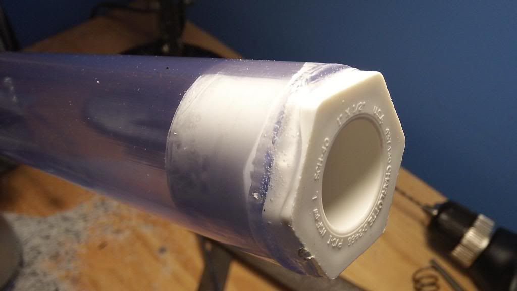
At this point, your goop is likely dry. Trim off any extra goop that protrudes outside of the diameter of the clear PVC. No need to trim the rest.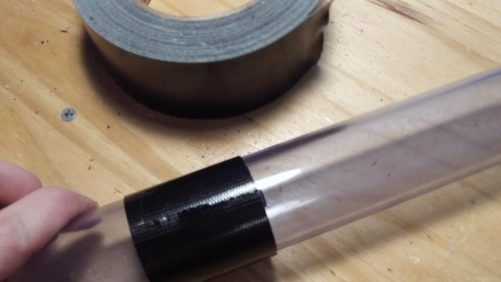
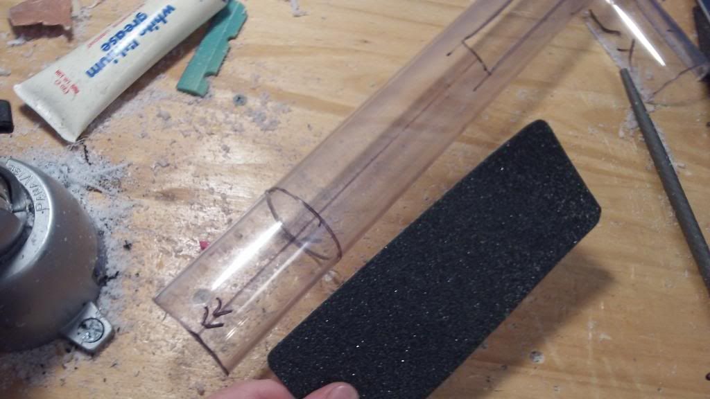
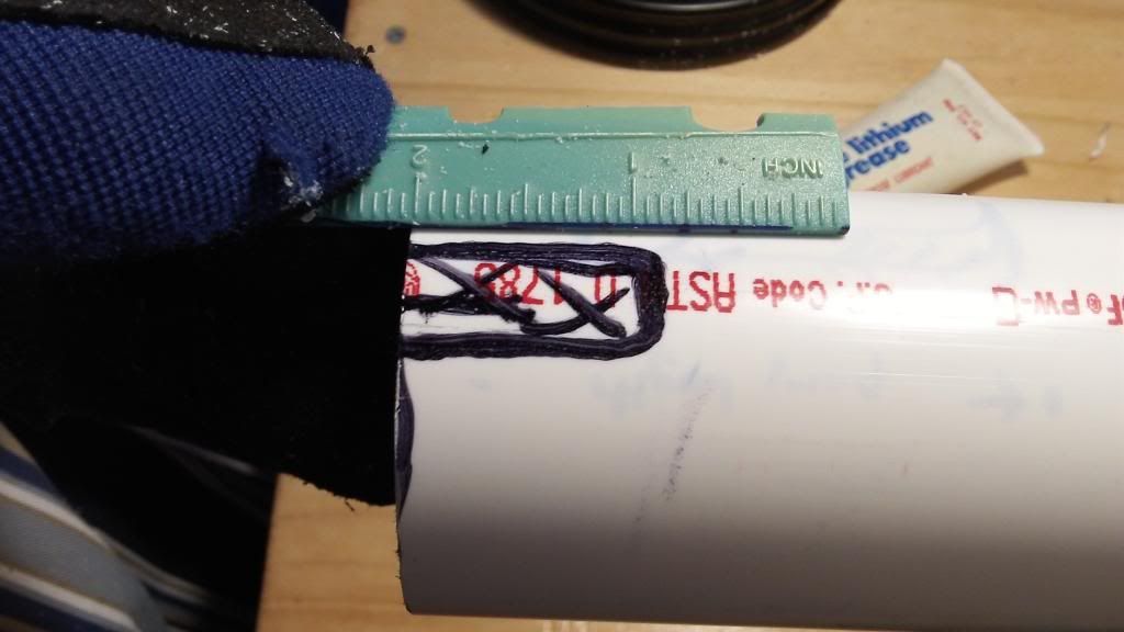
Measure out 11-1/2" from the front of the clear PVC and make a mark on the PVC. Using your gorilla tape, wrap around the tube at the mark, and trace around the tape.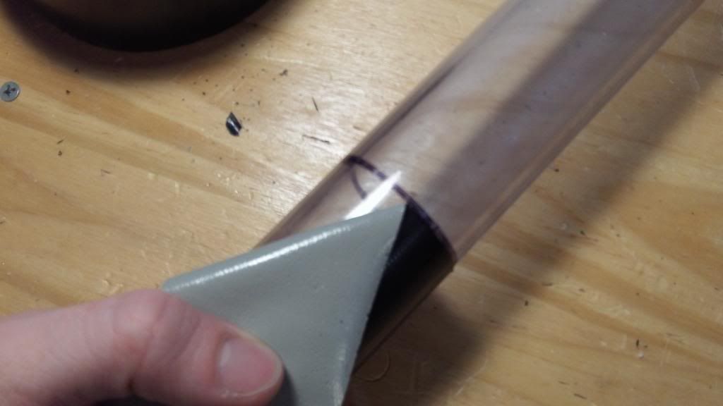
When the tape is removed, a circumference of distance 11-1/2" from the front of the PVC remains. This allows for clean placement of screws in the blaster.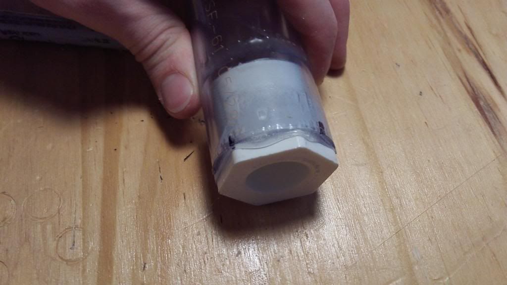
Make four marks around the front of the blaster. These marks can be accurately placed using the hexagonal bushing to locate the marks; one on each of two opposite corners of the hexagon, and one on each of two opposite sides of the hexagon.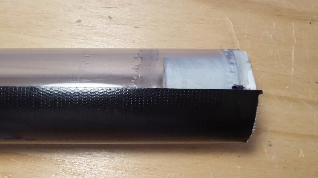
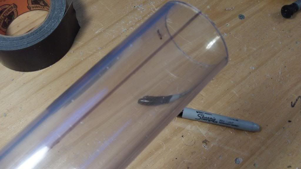
Using gorilla tape again, stretch the tape from the mark to the opposite end of the tube. Ensure it's straight, then draw a line from front to back on each of the four marks.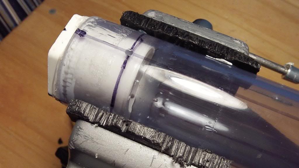
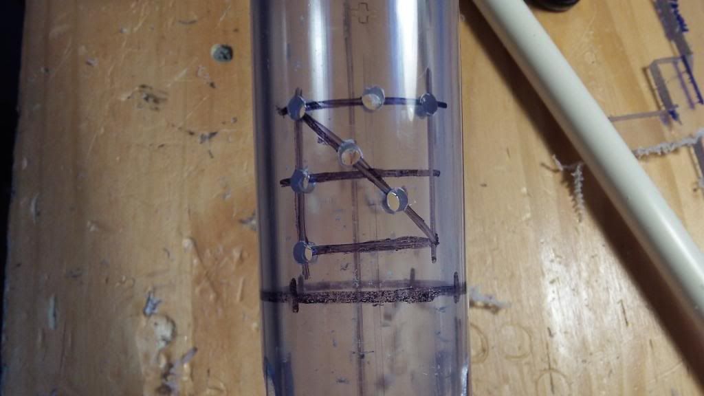
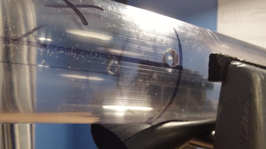
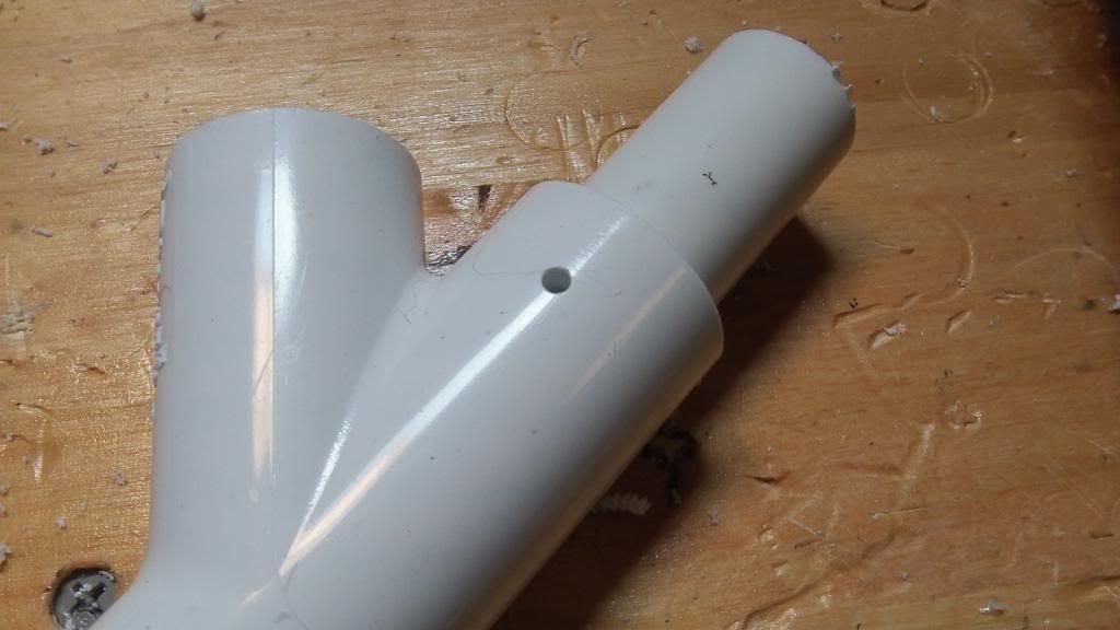
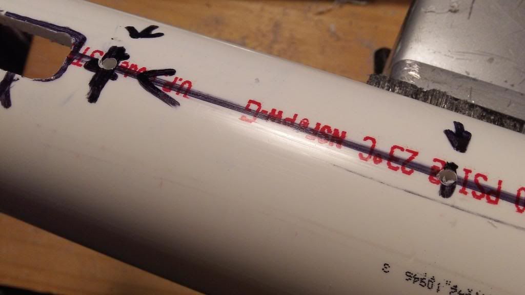
Mark a circumference about 1/4" from the rear of the PVC bushing. There are now four points of intersection between this ring and the four straight lines. Drill 7/32" holes on each of these points.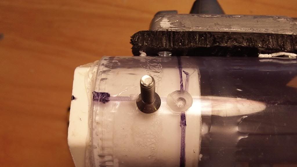
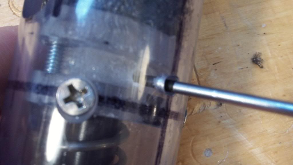
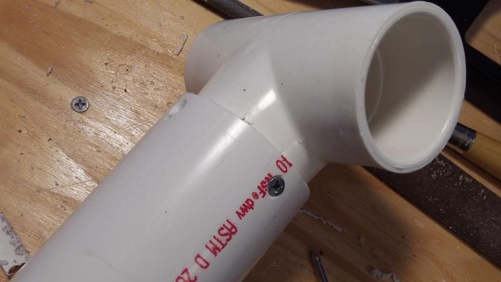
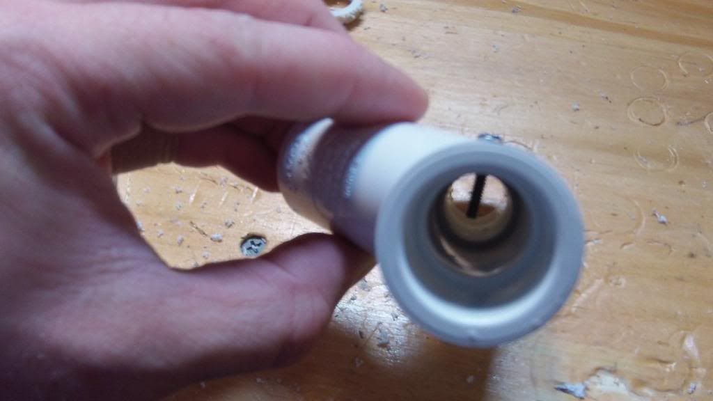
Countersink these 4 holes so the opening is the same size as the head of the flat headed 6-32 screws. Screw them into place. Tapping here is optional, only because the PVC is so soft. If you are having difficulty in securing the screws, by all means tap the holes with the 6-32 tap. The heads of the screws should be approximately flush with the PVC tube.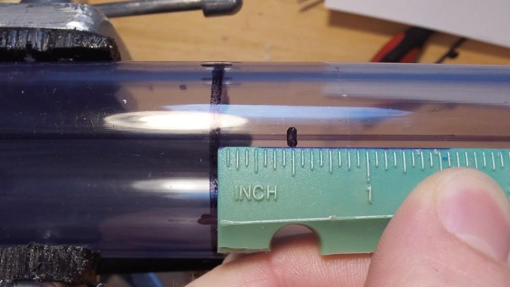
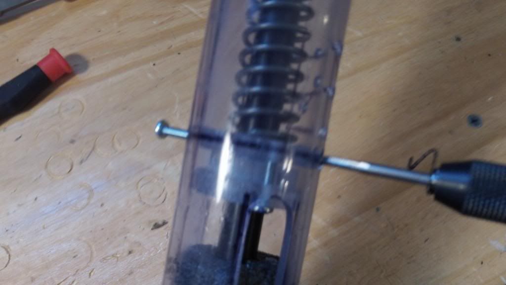
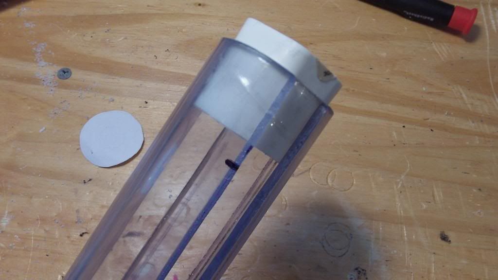
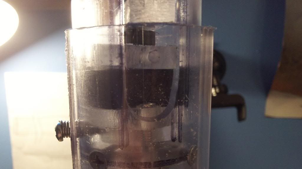
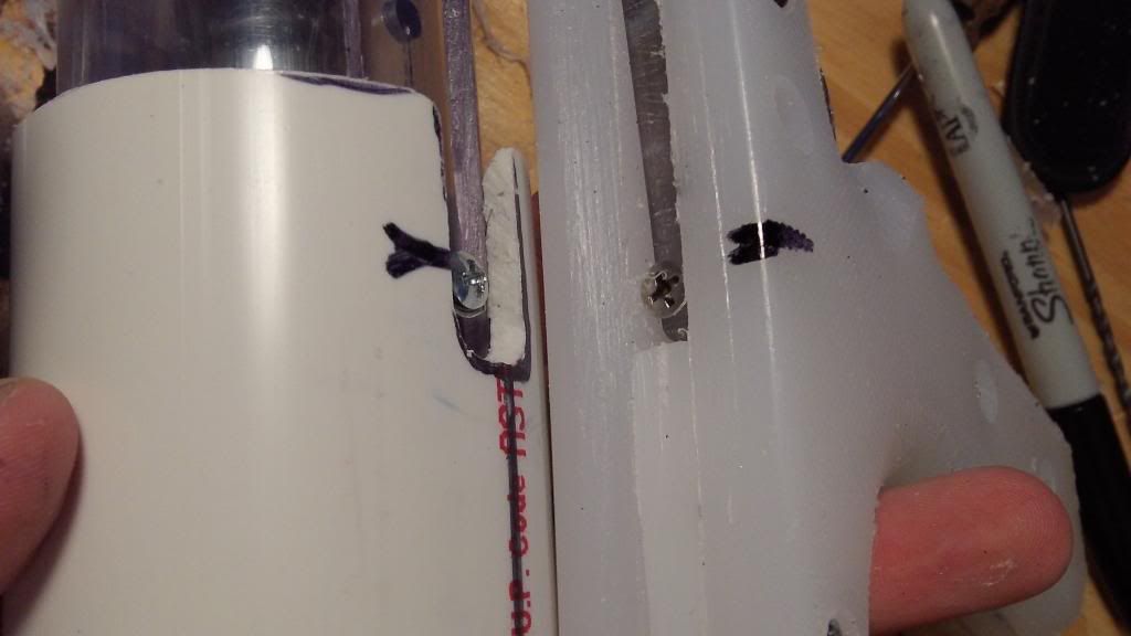
This is where the catch shall go inside the PVC tube. On the left hand side is the circumference where the forward-most catch plate will rest. Make a mark between each of the straight lines on this circumference. This is where screws will eventually anchor the catch to the PVC tube.
The mark on the right is made 1/2" to the rear of the catch circumference. This marks the extrema of the slots.
Slots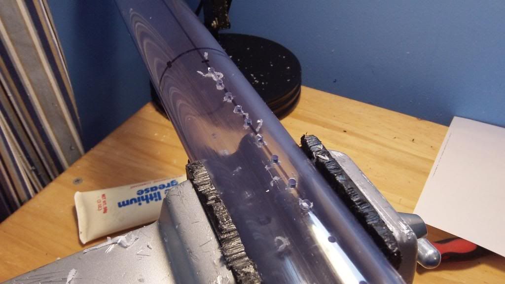
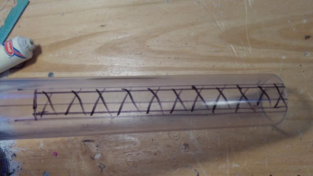
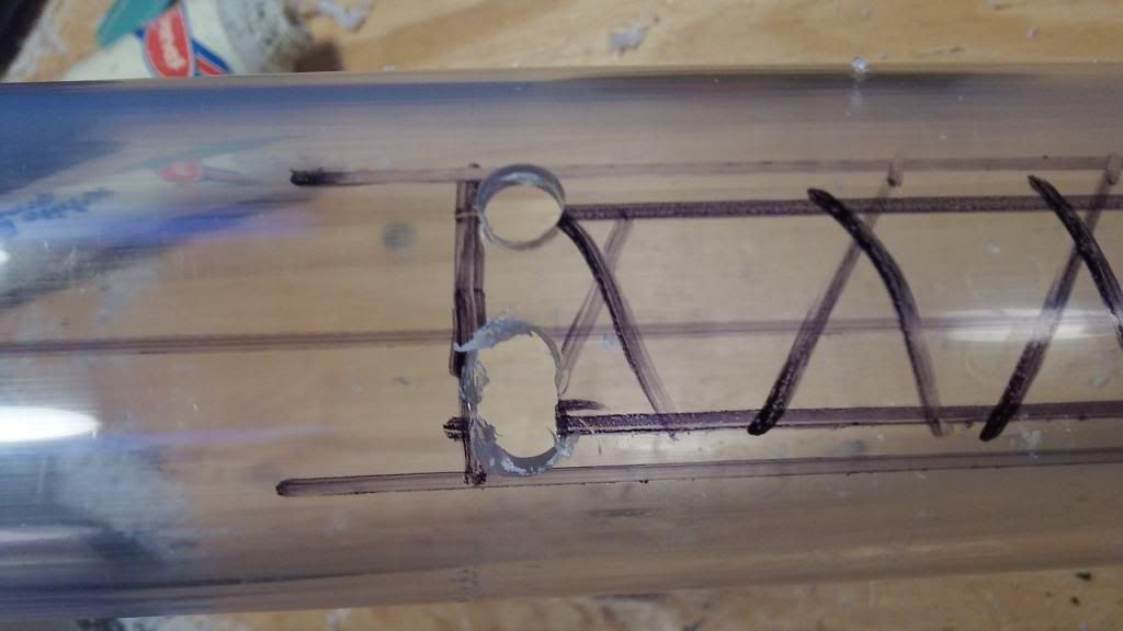
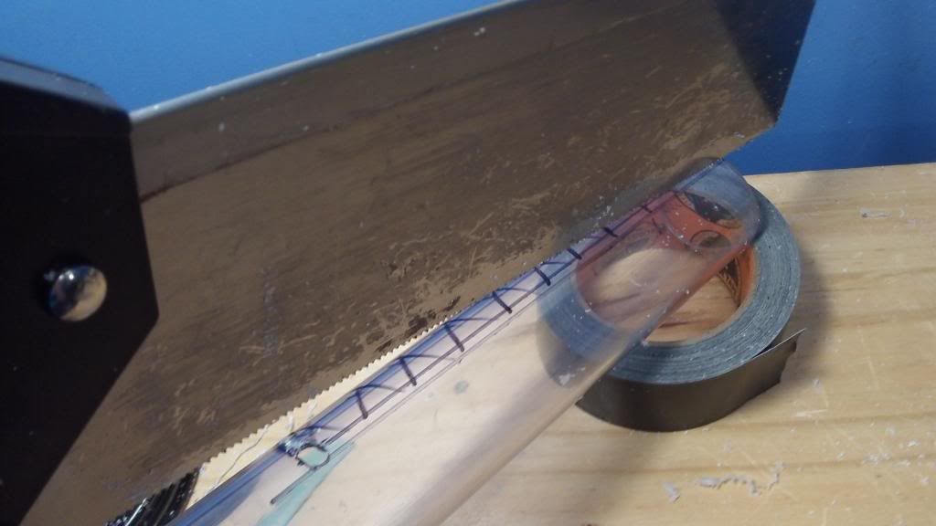
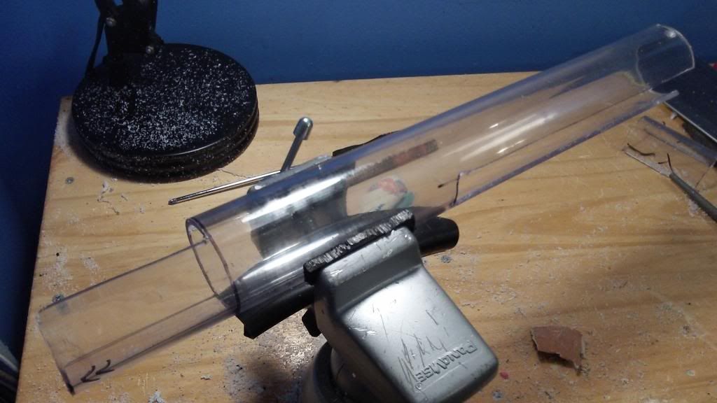
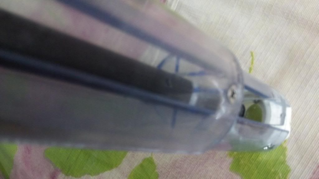
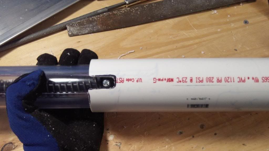
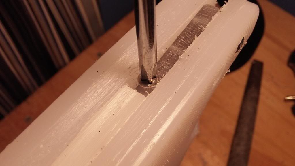
Start by drilling many small holes down the 2 lines on the sides of the blaster, beginning from the previous mark just behind the catch circumference. These slots will eventually extend all the way to the rear end of the blaster, but this method seems to make for straighter slots, as opposed to simply hack-sawing from the rear of the blaster to cut out the channels.
Widen the holes to about 7/16 wide. If this diameter is not achieved, there is no need to worry....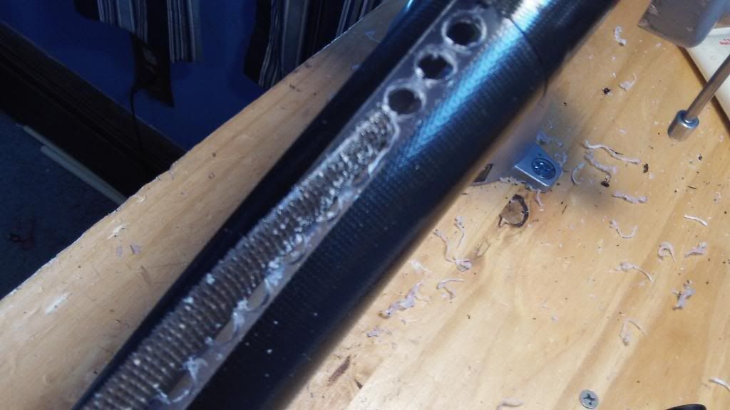
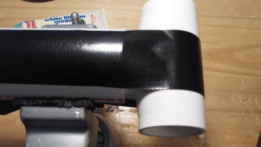
The slots will be widened using the file. The gorilla tape initially protects the rest of the PVC tube.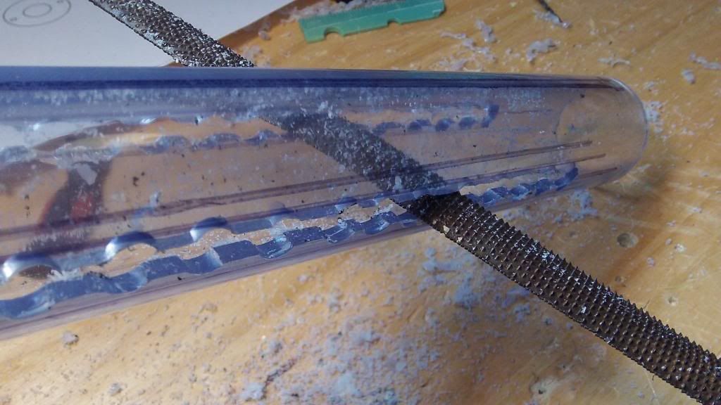
When finishing the slots, draw a line using this gorilla tape on each side of the holes. CAREFULLY file up to these lines.
Edited by Aeromech, 23 November 2015 - 01:32 AM.


