Jump to content


Photo

A New Style Pumpaction Snap Writeup for New Members

Essentially Daniel Beaver's Writeup with More Pictures
homemade pumpaction SNAP spring writeup

26 replies to this topic

#1 Naturalman7

Naturalman7

    Member

  • Contributors
  • 158 posts

Posted 26 August 2013 - 10:56 PM

I'll start off by saying all credit to Daniel Beaver for the design, but I felt that the write-up was not simple enough for a relatively new homemade maker to follow. I feel this way because the first time I attempted this I was a bit confused. The format of this follows the original write-up, but with more pictures and words. I know that this isn't the most up-to-date pump-action SNAP, but I liked its simplicity. Here is the link to the original write up: A new style Pump-action SNAP. Onto the write-up.

Pictures and text are arranged in text-then-picture format.

I tried to use all of my own photos, but my Lowes randomly stopped stocking things. First world problems.


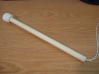
The finished product:

9e3a2c3b-5379-4c83-a68f-4ecc45f29d5a_zps


Materials List:


  • 1-1/4" PVC Coupler x2
  • 1-1/4" to 1/2" PVC Bushing
  • 1.25" PVC Regular Walled (480 PSI)
  • 1.5" PVC Thin wall (160 PSI) Note the differences in PSI rating/wall thickness.
  • 3/4" PVC Endcap x2
  • 1/2" PVC Endcap
  • 1/2" CPVC Coupler
  • 1/2" CPVC Endcap
  • 6-32x3/8 Machine Screw x2
  • Roofing Nail
  • Clothespin
  • 10-24x2" Machine Screw
  • 10-24 Locking Hex Nut
  • 3/16 x 1-1/4 x 1/16 Rubber Washer
  • 3/16 x 1-1/2 x 1/16 Rubber Washer
  • 3/16 x 1-1/4 Fender Washer
  • 8-32x1" Machine Screw
  • #6 x 9/16" Fender Washer
  • #10 Flat Washer
  • 1-½" Angle Bracket
  • 8" Ziptie
  • 4" Ziptie x2
  • 1/4" Steel Rod
  • 1/2" CPVC
  • 1-1/4" PVC Tee
  • String/rope of some type. I used 3/16" Mason Line (the cheapest rope I could find)
  • 1x2 Poplar Wood for handle
  • #6 1-1/4" Self Drilling Bolts x2 (If you cannot find/do not have self drilling bolts, then you can just drill a pilot hole first. I like the extra step saved of self drilling)
  • Cut-to-Length Compression Spring Spring-Tempered Steel, 11" L,.844" OD, .08" Wire. Available from McMaster-Carr in packs of 5. Item #9637K26.
  • 1" Metal Washer with 5/8" Inner Diamater (This piece is optional. It increases durability on the catch and is recommended in Daniel Beaver's original write-up, but I've had PumpSnaps last just fine without it. If you can find one with a 5/8" ID, all the better. If not, not a major loss.)

Necessary Tools:

  • Drill with a typical range of bits. If you must know, I used 7/64, 1/8, 9/64, 5/32, 3/16, 1/4, 7/16 bits and a 5/8 spade bit.
  • PVC/CPVC Cement (Multipurpose Cement. AKA Solvent Weld)
  • Dremel with cutting, sanding, and grinding bits.
  • Hacksaw (a mitre box helps)
  • Scissors
  • Packing tape if your 3/4" PVC Endcap is too small to fit snugly in 1.25" PVC, otherwise it is not needed.
  • Hammer
  • Screwdriver (or a driver bit for a drill/driver)

Helpful but optional tools:

  • Sandpaper for deburring and helps clean things up a bit
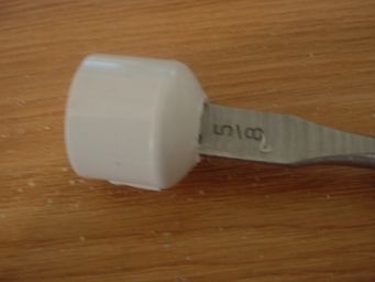
  • I find that a mallet (as pictured) makes getting the fittings into each other easier without damaging the weak PVC plastic.

Onto the building:

The Front Coupler (and also the easiest step of this build)

Parts:

  • 1-1/4" PVC Coupler
  • 1-1/4" to 1/2" PVC Bushing

Tools:

  • Solvent Weld

I don't think this needs a lengthy description. Just solvent weld the two fittings into each other. This will be added to the front of the blaster later on. (Picture borrowed from Daniel Beaver's original write-up because I think my local hardware store stopped stocking them. Couldn't find an empty shelf for them or anything.)

01-Coupler_zpsd138dd7c.jpg
All credit for this photo goes to Daniel Beaver.


The Plunger/Plunger Head

Parts:

  • 8-32x1" Machine Screw
  • #6 x 9/16" Fender Washer
  • #10 Flat Washer (Not pictured, just using one or the other seems to work. Original guide used two washers.)
  • 3/16 x 1-1/2 x 1/16 Rubber Washer
  • 3/16 x 1-1/4 x 1/16 Rubber Washer (The second rubber washer is to prevent shearing.
  • 3/16 x 1-1/4 Fender Washer
  • 1/2" CPVC Endcap
  • 1/2" CPVC

Tools:

  • Hacksaw
  • Drill
  • 9/64" Drill bit
  • Solvent Weld

Assembly:

Cut a 7" segment of CPVC with the hacksaw. The final product of this step will be assembled as pictured.

DSCF0184_zps165611ba.jpg

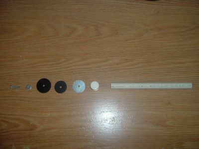
Mark the center of the endcap and drill a 9/64" pilot hole for the #8 machine screw. An easy way to get the mark centered is to use a descending size of concentric cylinders. Eg placing the sharpie in a section of CPVC.

DSCF0185_zps7c0df73e.jpgDSCF0188_zpsf13749d0.jpg

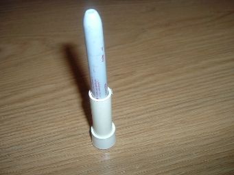
Tighten the bolt so that the rubber washers form a cup shape. This assembly is called the plunger head (PH) and forms the air seal of the blaster.

DSCF0189_zpsea5d8fc6.jpg

After assembling the plunger head (PH) onto the endcap, solvent weld the PH onto the CPVC segment.

DSCF0190_zps7813c3cf.jpg


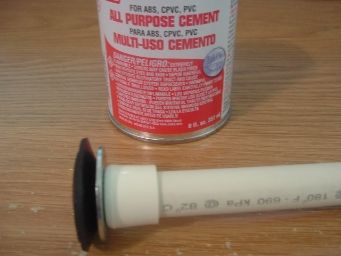
Onto the most complicated part (build wise)

The Catch Assembly

Parts List:

  • 3/4" PVC Endcap (Not flat-topped)
  • 1/2" PVC Endcap
  • 1/2" CPVC Coupler
  • 1/4" Metal Rod. You can use a smaller diameter rod, but keep in mind that this piece is used to hold the force of the spring when/if dry firing.
  • 1" Metal Washer with 5/8" Opening
  • Rope for string stop
  • Main Spring, the [k26]
  • CPVC

Tools List:

  • Drill with bit the same diameter as the metal rod
  • 5/8" Spade Bit
  • Hacksaw
  • Hammer
  • Dremel with sanding drum
  • Solvent Weld
  • Scissors

Assembly:

The idea behind this that is different than a tradition pull-back SNAP is that the catch is far enough behind the air seal. You'll need to first drill and sand out the 3/4" PVC endcap to fit the 1/2" Endcap and CPVC coupler inside of it. I did this by drilling the endcap with a 5/8" bit then sanding it down with a sanding wheel. The end of the CPVC coupler should be able to fit entirely within the 3/4" PVC endcap.

DSCF0196_zps692fa179.jpg

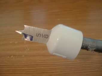
Depending on the brand of fitting, you will probably have to sand the fittings down further. The 1/2" Endcap I used had a small part that stuck out that needed sanding before it could fit inside the 3/4" endcap. In addition to that, you'll also have to drill/sand the 1/2" endcap so the CPVC coupler will fit.

DSCF0193_zpsa1a6e1ae.jpg

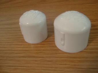
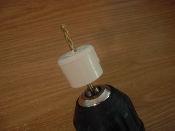
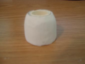
After the fittings have been drilled and sanded, hammer them into each other. I would recommend hammering the parts into each other smallest to largest, but it doesn't really matter as long as you don't try to do all three at once like pictured.

DSCF0197_zpsb46aa5c4.jpg

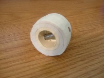
Sand down the bottom of the fittings so they're flush and then sand the outside of the fittings so that the whole piece fits into the 1-1/4" PVC without resistance.

DSCF0198_zps41553414.jpgDSCF0201_zps1fc02cac.jpg

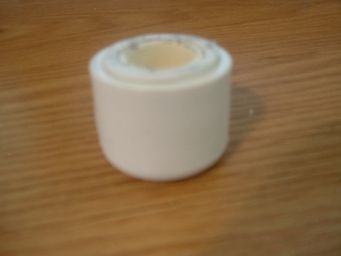
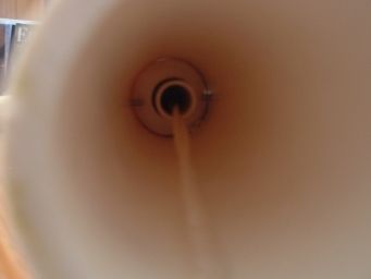
Take the metal rod, measure it to the diameter of the catch assembly, cut it, then drill through the catch assembly around the middle of the CPVC coupler that's on the inside of the assembly. Hammer the piece of rod into the holes on both sides of the catch, as pictured.

DSCF0203_zps7ec03b8c.jpgDSCF0204_zpsea3d7d37.jpg

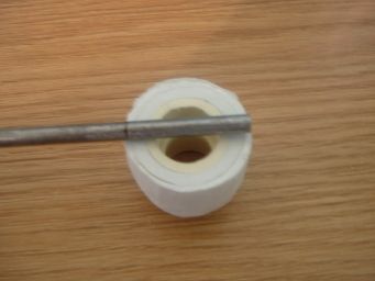
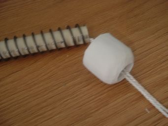
Cut the final piece of CPVC, 12" length, and thread the string through the spring, CPVC, and catch. Loop the spring back through and around the metal rod back out the end of the CPVC. Spring isn't pictured because I chose to put it on later.

DSCF0206_zps725b5843.jpgDSCF0207_zps738a6f42.jpg

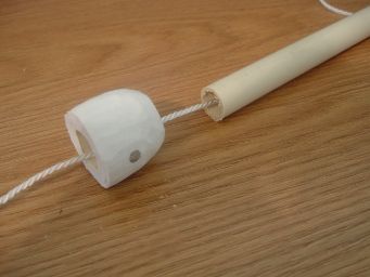
Attach the front half of the plunger rod and the metal washer with 5/8" inner diameter to the rest of the plunger rod. The washer provides some support for the catch.

DSCF0226_zps6c775e0d.jpg

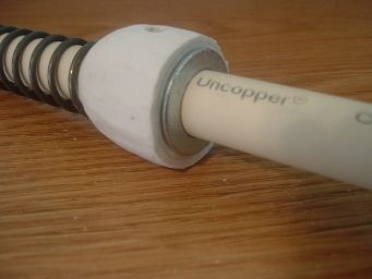
The rear section of CPVC keeps the spring centered and stable as well as sheathes the string. Tie a knot in the end of the rope to keep it together or always hold both ends of the rope at a time. If you drop it and the string comes out, it'll take hours to get it back through.

August 27,2013 Edit: This is what it should look like when it's assembled with the string and everything. All credit for this photo goes to Daniel Beaver.
05-Pluger-Rod_zps569c6fa2.jpg


Main Body

Parts:

  • 1.25" PVC

Tools:

  • Hacksaw
  • Drill with 1/4" and 9/64" bits
  • Dremel with cutting wheel. Daniel Beaver recommends a diamond cutting disk. I concur and have it pictured.
  • Measuring device

Building:

Cut the 1.25" PVC 25" long.


Measure and mark 7" from the front and mark 6" from the first.

DSCF0212_zps88cef050.jpg


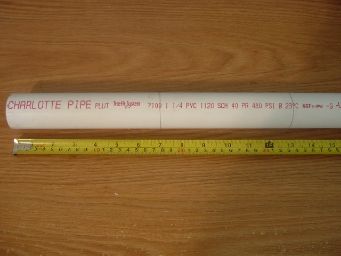
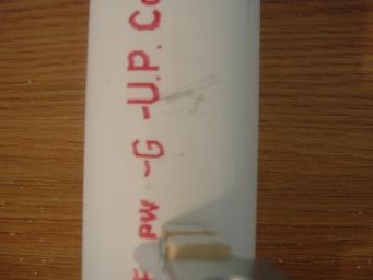
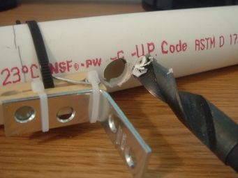
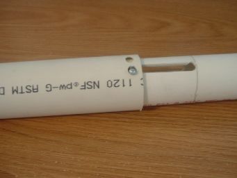
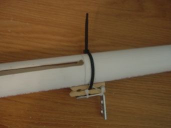
Within these two marks you will need to cut two slots for the priming slide. The slot should be placed near the top of the blaster as pictured. The best method is generally to drill a pilot hole, then turn the bit sideways and drill through the other side. Once you make four holes, cut along the length of the body with the cutting wheel. It's best to do the main body and the priming slide at the same time so you can check the fit/placement of the holes and slots as you cut them. Otherwise, you may end up with holes in the wrong spots as in my example. Hopefully there are enough pictures to explain this clearly. My example isn't very straight, but you can trim it up during the cutting process.

DSCF0214_zps743794c2.jpg

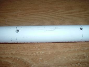
After you finish the slots, drill a 9/64" hole on the inside of the second line on the bottom of the body (opposite of the slots). This hole will be for the trigger roofing nail.


Priming Slide

Parts:

  • 1.5" Thin wall PVC
  • 10-24x2" Machine Screw
  • 10-24 Locking Hex Nut

Tools:

  • Drill and 1/4" bit
  • Dremel with cutting bit

Cut the 1.5" PVC to around 6.25" long. On the 6" mark, drill a 1/4" hole similarly to the way done on the main body. Check the fit and location of the holes before you drill them, it'll help prevent a mistake. Measure twice, cut once.

DSCF0216_zps40a75e55.jpgDSCF0218_zps72f59194.jpg

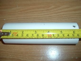
After the trigger is attached to the body, mark and cut a slot into the priming slide to fit around the trigger. See further into this guide.


Trigger

Parts:

  • 4" Zipties x2
  • 8" Ziptie
  • Angle Bracket
  • Roofing Nail
  • Clothespin
  • Main Body

Tools:

  • Hacksaw
  • Drill w/ 9/64" bit
  • Dremel with grinding wheel

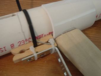
Cut the clothespin right behind the spring.

DSCF0208_zps2753d735.jpg

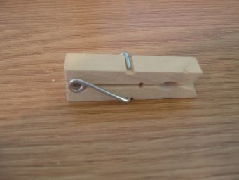
Drill a hole through the clothespin for the roofing nail.

DSCF0209_zps7f694eac.jpg

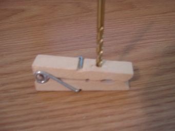
Attach the angle bracket with the 4" zipties over the roofing nail. I recommend putting the ends of the zipties away from your hand, the side the "head" of the ziptie should be on depends on your dominant handedness.


Grind down the roofing nail so it is shorter and rounded. I prefer to trim the nail to the desired length after the spring is installed, but I like to use the clothespin as a reference of where to put the handle which will be discussed later.

DSCF0220_zps55def4b4.jpg

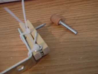
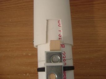
Then, attach the trigger to the main body.
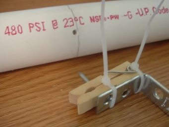
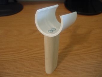
DSCF0219_zpsbcb42751.jpgDSCF0228_zpsf5241eb6.jpg


Handle

Parts:

  • 1-1/4" PVC Coupler
  • #6 1-1/4" Self Drilling Bolts x2
  • 1x2 Poplar Wood for handle
  • Main Body with Trigger attached

Tools:

  • Hacksaw
  • Drill with driver bit and 7/16" bit
  • Sandpaper for smoothing grip


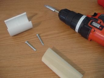
Cut and sand down the handle to the shape and comfort you want. Then cut 1/4 of the coupler away and sand down the ridge in the middle of the coupler. I just use a hacksaw to cut the coupler which is probably not the safest option, but if you're slow and steady you'll win the race. Attach the two pieces together and you have your handle. Not pictured, but suggested, is to use hotglue to temporarily hold the wood onto the coupler which makes putting the screws in a lot easier.


DSCF0222_zpsd38cbbf5.jpgDSCF0223_zpsb646a9d0.jpgDSCF0227_zps3e4f8b9d.jpg


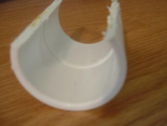
Edited by Aeromech, 23 November 2015 - 12:23 PM.

  • 0

#2 Naturalman7

Naturalman7

    Member

  • Contributors
  • 158 posts

Posted 26 August 2013 - 11:28 PM

After the handle is assembled, snap it onto the main body behind the trigger. Having the handle directly behind the trigger prevents any over travel (as on a regular SNAPbow mk V). If you've made a SNAPbow before, you'll know what to do. Slide the handle back and forth to create marks where you'll drill two 7/16" holes and glue the handle onto.

Posted ImagePosted ImagePosted Image

After the handle is glued on is usually where I cut the slot in the priming slide. Just needs to be large enough to not hit the trigger on the prime.

Posted Image


Spring Rest

Parts:
  • 3/4" PVC Endcap
  • Packing Tape (if your endcap isn't wide enough to fit snugly in the main body on its own)
  • 6-32x3/8" Machine Screws x2

Tools:
  • Drill with 7/64" bit and 5/8" Spade bit
  • Dremel with sanding drum


Take the 3/4" PVC endcap and drill a 5/8" hole in the center. You will likely have to widen it to allow the CPVC to slide freely through it without too much friction.

Posted Image

If your endcap is too tight or too loose, sand it down or add packing tape, respectively.

Lubricate the plunger head and the inside of the main body. Slide the string from the plunger rod through the endcap and pull the whole assembly through the front of the blaster.

Posted ImagePosted Image

Position the spring stop and the plunger rod so that the catch face is ~1/2" away from the priming bolt and make sure the PH isn't beyond the front of the body or you've seriously messed up a measurement. Drill the 7/64" holes and add the #6 screws to hold the spring stop in place (see picture). The spring shouldn't have any compression when the PH is all the way forward.

Posted ImagePosted Image


Stock and String Stop The final piece of the puzzle

Parts:
  • 1-1/4" PVC Tee

Tools:
  • Drill and a large enough bit that you can thread the string through, but small enough that you can tie a knot in the string and not have the knot slip through the hole.

The string stop in the stock makes this blaster dry fire safe. At least, safer. Adjust the length of the string and the position of the knots so that the length is right. Having the length right will make the blaster noticeably quieter when fired.

Posted Image


Other Dimension(s) not previously stated because they're redundant but in Daniel Beaver's original write-up:

I might add a diagram of all the dimensions if I'm bored and feel it necessary.
  • Length from front of slot to spring rest screws: Length of spring + 2"

If I'm missing anything, please do tell.


Again, all credit to Daniel Beaver for the design.

Edited by Naturalman7, 20 January 2014 - 02:02 PM.

  • 0

#3 andtheherois

andtheherois

    Member

  • Banned
  • 821 posts

Posted 27 August 2013 - 07:57 AM

Good write up, though a few things.

You didn't show the full plunger rod. I think it'd be helpful for people to see what it looks like fully assembled. I also think it would help to show a picture of the front coupler assembled. Not everyone has played with PVC ;)

I think finding the 5/8 washer will be a bit of an issue for some people. I know Lowes carries them in 2 packs. Other than that I'm not sure where.

I would suggest against solvent welding the plunder head on, and instead using bolts. That way you can replace it in case the plunger head suffers any damage.
The YooToobz
Photobucket

Winning rounds is rewarding, deal with it. We don't play fucking patty cake over here.


#4 cheerios

cheerios

    Member

  • Members
  • 396 posts

Posted 27 August 2013 - 09:15 AM

I would suggest offering an alternative possibility for the 5/8" washers as well as the thinwall PVC, not all people have these at their local hardware stores.
  • 0
22:46- jakejagan :Ryan, did you hear that Zeke's BBBB made N9 bleed?
22:47- Zorn :BONUS

#5 DartSlinger

DartSlinger

    Member

  • Members
  • 222 posts

Posted 27 August 2013 - 02:56 PM

Here is an alternative to using thinwall PVC.

Edited by DartSlinger, 27 August 2013 - 03:05 PM.

  • 0

#6 Naturalman7

Naturalman7

    Member

  • Contributors
  • 158 posts

Posted 27 August 2013 - 05:04 PM

1: . . ..You didn't show the full plunger rod. I think it'd be helpful for people to see what it looks like fully assembled. I also think it would help to show a picture of the front coupler assembled . . .

2: I think finding the 5/8 washer will be a bit of an issue for some people. I know Lowes carries them in 2 packs. Other than that I'm not sure where.

3: I would suggest against solvent welding the plunder[sic] head on, and instead using bolts. That way you can replace it in case the plunger head suffers any damage.

1: I showed both halves of the plunger connected and the place where they connected, I assumed that would be enough.
2: I thought it worth adding because in the original write-up it mentioned them, but wasn't very clear about them. If you can find them, bonus points to you. If not, you aren't missing out on a lot. I've had three of these for several years now and haven't had one break/wear out beyond use. I actually widened the ID of 1" washers because I couldn't find them at my local stores.
3: I've had problems with PHs breaking where bolts were attached. It's probably just because I used too large of screws, but whatever. The most damageable part of the PH is the rubber washer and if it needs replaced it can just be removed by unscrewing the #8 bolt.


I would suggest offering an alternative possibility for the 5/8" washers as well as the thinwall PVC, not all people have these at their local hardware stores.

The 5/8" washer isn't required and as such the alternative would be to just not include it. The thinwall PVC you make a moot point. However, if my little town outside of Boise, Idaho has thinwall, I'd be shocked if most other stores didn't. Anyway, I'll add the dual-coupler alternative.

Here is an alternative to using thinwall PVC.


Thanks for the feedback. I will update the OP(s) with the relevant information shared.
  • 0

#7 PBZ

PBZ

    Cap'n Whitebeard

  • Members
  • 142 posts

Posted 28 August 2013 - 12:06 PM

Are there any large differences in the action of using this version versus the original write up? Your plunger head seems to be missing a few pieces for the catch, and that would affect how you pump it? There is no ramp for the nail to ride on, so you have to pull the trigger just to prime it? For just a few ectra parts, wouldnt it be easier to operate?
Not to "start something" as kids these days say, but I think the original was a little better than this one. Ok, yeah, starting something.
  • 0
"There's nothing quite like hunting children." -VACC

#8 DartSlinger

DartSlinger

    Member

  • Members
  • 222 posts

Posted 28 August 2013 - 01:02 PM

Your plunger head seems to be missing a few pieces for the catch, and that would affect how you pump it? There is no ramp for the nail to ride on, so you have to pull the trigger just to prime it?

Here is the catch. It's perfectly functional, and the catch ramp is the nested PVC.

Posted Image


  • 0

#9 HasreadCoC

HasreadCoC

    Member

  • Members
  • 274 posts

Posted 28 August 2013 - 02:34 PM

Here is the catch. It's perfectly functional, and the catch ramp is the nested PVC.

Posted Image

As someone who's never built a SNAP, I must say, this design looks so much better than using putty.

Edited by HasreadCoC, 28 August 2013 - 02:34 PM.

  • 0

I'm the only respectable person here. The rest of the NIC are pretty much just child molesters.


AKA: ObiWonTwo on Nerfrevolution, and most of the rest of the internet for that matter.....

#10 Daniel Beaver

Daniel Beaver

    HQRSE CQCK

  • Moderators
  • 2,097 posts

Posted 28 August 2013 - 03:32 PM

Looks good. I still consider this design "superior" to the Quixote, it's just a lot more work to build. The one I built for the original writeup still works, even after two years of use and very little maintenance.


As someone who's never built a SNAP, I must say, this design looks so much better than using putty.

As someone who has built many of both types, I think they're about equal in terms of performance and build difficulty. I don't build these all-PVC catches anymore because I'm pretty sick of breathing PVC dust while grinding down ramp enough for it to catch smoothly.
  • 0

#11 DartSlinger

DartSlinger

    Member

  • Members
  • 222 posts

Posted 28 August 2013 - 03:34 PM

As someone who's never built a SNAP, I must say, this design looks so much better than using putty.

It just might be. It could be less durable though, because the catch ramp is made of PVC, which is softer than epoxy putty.
  • 0

#12 Naturalman7

Naturalman7

    Member

  • Contributors
  • 158 posts

Posted 28 August 2013 - 06:45 PM

Are there any large differences in the action of using this version versus the original write up? Your plunger head seems to be missing a few pieces for the catch, and that would affect how you pump it? There is no ramp for the nail to ride on, so you have to pull the trigger just to prime it? For just a few ectra parts, wouldnt it be easier to operate?
Not to "start something" as kids these days say, but I think the original was a little better than this one. Ok, yeah, starting something.

The 3/4" PVC endcap is the catch ramp. It's the same way as in the original write up.


Looks good. I still consider this design "superior" to the Quixote, it's just a lot more work to build . . ..


As someone who has built many of both types, I think they're about equal in terms of performance and build difficulty. I don't build these all-PVC catches anymore because I'm pretty sick of breathing PVC dust while grinding down ramp enough for it to catch smoothly.

I was just about to build a Quixote to compare to other types of pump-action homemades. However, if I had the money and skills to make a rainbow pump, I would probably find that it's the best.

As for ramps, I too hate getting PVC dust everywhere and prefer to use putty. I probably did something wrong, but I've had two putty ramps break on me and had to replace them. Drilling and sanding and hammering and sanding again makes PVC ramps much more difficult in terms of building than mixing and forming putty. It's as easy as playing with play-doh.


It just might be. It could be less durable though, because the catch ramp is made of PVC, which is softer than epoxy putty.

It doesn't make a huge difference in my opinion. Both last very long.
  • 0

#13 Daniel Beaver

Daniel Beaver

    HQRSE CQCK

  • Moderators
  • 2,097 posts

Posted 28 August 2013 - 07:07 PM

I was just about to build a Quixote to compare to other types of pump-action homemades. However, if I had the money and skills to make a rainbow pump, I would probably find that it's the best.

Do that, I'm interested to hear someone else's opinions about how these two blasters compare build-wise and performance-wise.

As for ramps, I too hate getting PVC dust everywhere and prefer to use putty. I probably did something wrong, but I've had two putty ramps break on me and had to replace them. Drilling and sanding and hammering and sanding again makes PVC ramps much more difficult in terms of building than mixing and forming putty. It's as easy as playing with play-doh.

How did they break? Did they crack? Did the epoxy separate from the washer?
  • 0

#14 Ivan S

Ivan S

    Member

  • Members
  • 123 posts

Posted 29 August 2013 - 03:13 PM

I probably did something wrong, but I've had two putty ramps break on me and had to replace them.


I also had several catch ramps break on me, until I realized that Oatey brand putty(which is the kind in hardware stores I've been to) is much softer than Loctite. I think that's a problem a lot of people run into but never work out. Once I started using Loctite I never had a problem.

And while I was using Oatey putty I came up with a method that can make ramps harder, which is to coat them in a thin layer of JB Weld. The very first snapbow used a pvc ramp, but the community moved away from that because steel wears down plastic over time. Maybe a layer of JB Weld would prevent that problem.

Edit: This is kind of off topic, but I wonder if using a thin polycarbonate rod instead of a nail would work and keep a plastic ramp from wearing down? It's certainly not something for a beginner write-up, and might not be worth doing at all, but maybe.

Edited by Ivan S, 29 August 2013 - 03:19 PM.

  • 0
You can never take nerf too seriously, but you can easily take yourself too seriously.
~Talio

#15 Daniel Beaver

Daniel Beaver

    HQRSE CQCK

  • Moderators
  • 2,097 posts

Posted 29 August 2013 - 04:19 PM

but the community moved away from that because steel wears down plastic over time.

I've come to the opinion that this is a total non-issue. The front face needs metal reinforcement, but action of the nail scratching on the side of the PVC causes only minimal damage even after very extensive use. SNAP plunger heads need to be refurbished after 5 wars or so anyhow.
  • 0

#16 Naturalman7

Naturalman7

    Member

  • Contributors
  • 158 posts

Posted 29 August 2013 - 04:46 PM

Do that, I'm interested to hear someone else's opinions about how these two blasters compare build-wise and performance-wise.


How did they break? Did they crack? Did the epoxy separate from the washer?

I was going to try to come up with my own variant on a PS3.0 first, but I'll to a Quixote as soon as I can. They ramps cracked and broke into three pieces. Separated from both the washer and CPVC. I found out they broke when it wouldn't prime and there was rattling inside the pressure chamber.

@Ivan S
PVC durability isn't really the issue, it's the difficulty of making it. If the nail is ground smooth enough anyway, there's hardly any wear.

Edited by Naturalman7, 29 August 2013 - 04:47 PM.

  • 0

#17 PBZ

PBZ

    Cap'n Whitebeard

  • Members
  • 142 posts

Posted 30 August 2013 - 10:12 AM

Here is the catch. It's perfectly functional, and the catch ramp is the nested PVC.

Posted Image


Ok, I got it now- but this brings up another question, and maybe im still just not seeing it right- on the original write up, the space for the nail catch is about 1/4 to 1/2 inch- is yours just not compressed? or is it actual that long? doesn't this just extend the blaster unnecessarily?
  • 0
"There's nothing quite like hunting children." -VACC

#18 Naturalman7

Naturalman7

    Member

  • Contributors
  • 158 posts

Posted 30 August 2013 - 04:42 PM

Ok, I got it now- but this brings up another question, and maybe im still just not seeing it right- on the original write up, the space for the nail catch is about 1/4 to 1/2 inch- is yours just not compressed? or is it actual that long? doesn't this just extend the blaster unnecessarily?

I don't think that you're seeing it right. However, I'm also not sure what you're talking about. I think you're talking about the priming bar (the long bolt). The space is a little longer because I made the string stop shorter.
  • 0

#19 PBZ

PBZ

    Cap'n Whitebeard

  • Members
  • 142 posts

Posted 01 September 2013 - 08:38 AM

I don't think that you're seeing it right. However, I'm also not sure what you're talking about. I think you're talking about the priming bar (the long bolt). The space is a little longer because I made the string stop shorter.


In the OP edit from August 27 of the entire plunger rod system, the front section (where the nail moves upward and catches in the space in front of the ramp) looks like it is 4 or 5 inches long, and seems to be solid that way as there is a coupler inside the ramp. any particular reason you made it that long? doesnt it just adds length to the blaster?

Edited by PBZ, 01 September 2013 - 08:44 AM.

  • 0
"There's nothing quite like hunting children." -VACC

#20 Naturalman7

Naturalman7

    Member

  • Contributors
  • 158 posts

Posted 01 September 2013 - 08:54 AM

In the OP edit from August 27 of the entire plunger rod system, the front section (where the nail moves upward and catches in the space in front of the ramp) looks like it is 4 or 5 inches long, and seems to be solid that way as there is a coupler inside the ramp. any particular reason you made it that long? doesnt it just adds length to the blaster?

There's also a coupler inside my ramp. I don't think it adds extra length. And even if it did, it would be negligible.
  • 0

#21 DartSlinger

DartSlinger

    Member

  • Members
  • 222 posts

Posted 01 September 2013 - 02:48 PM

There's also a coupler inside my ramp. I don't think it adds extra length. And even if it did, it would be negligible.

What I think that PBZ is trying to ask is that why is there so much more space between the catch face and the plunger head on this design than on Nerfomania's design. For instance, here is a picture from Nerfomania's write-up.

Posted Image


Also, how long is this design (without a barrel), and is it longer than Nerfomania's design. (His design is about 27 7/8" long without a barrel.)
  • 0

#22 Phoenix66

Phoenix66

    Member

  • Members
  • 64 posts

Posted 01 September 2013 - 03:24 PM

It's hard to explain, but the plunger head is about 7 inches farther ahead from the actual catch piece. When the plastic chunk with the washer on it is at rest, it sits about 3/8s of a inch behind the front of the slot. When it's pulled back, and eventually gets caught, the plunger head is right in front of where the slot starts. There is a distance there that you normally don't get on a regular PumpSnap, because the slots are behind the handle, where here the slots are in front of the handle, so it's a different style of plunger rod.
  • 0

The more the merrier (except if you're a 10 year old with a foam sword. In which case - the fewer the better)


#23 Carbon

Carbon

    Contriberator

  • Moderators
  • 1,894 posts

Posted 01 September 2013 - 09:08 PM

Nice writeup, and a shout out for wooden clothespins. (This is where Beaver calls me a Socialist again.)

Anyway, a question about your catch face, as it appears to be hella ground down on the outermost layer. Compare your catch:

Posted Image

to Beaver's:

Posted Image

You can see how your outer most layer of PVC is at points a quarter of the thickness of the inner layer, whereas beaver's outer layer is the same thickness. I bring this up because in my experience, PVC fittings that are both hammered together and heavily ground down have a greater tendency to crack. That thin spot? It's probably going to end up cracking right there.
  • 0
Hello. I am Indigo of the Rainbow Clan. You Nerfed my father. Prepare to die.

#24 Daniel Beaver

Daniel Beaver

    HQRSE CQCK

  • Moderators
  • 2,097 posts

Posted 01 September 2013 - 09:38 PM

Nice writeup, and a shout out for wooden clothespins. (This is where Beaver calls me a Socialist again.)

Why do you hate America so much?
  • 0

#25 Naturalman7

Naturalman7

    Member

  • Contributors
  • 158 posts

Posted 02 September 2013 - 09:33 AM

Also, how long is this design (without a barrel), and is it longer than Nerfomania's design. (His design is about 27 7/8" long without a barrel.)

I like Phoenix66's answer to the question about the catch length. As for overall length, the one I made for this writeup was ~28.5" long without a barrel. There's some extra room that you could shorten the design by an inch if you wanted to, but it also doesn't have a ton of draw.

You can see how your outer most layer of PVC is at points a quarter of the thickness of the inner layer, whereas beaver's outer layer is the same thickness. I bring this up because in my experience, PVC fittings that are both hammered together and heavily ground down have a greater tendency to crack. That thin spot? It's probably going to end up cracking right there.

I'd say it's because my fittings and PVC didn't fit together very nicely and I went overboard on the sanding. You're right, of course, it could crack. When/if it does, I'll edit the write up for others to be aware of it. The only fitting I've had crack was a 3/4" PVC endcap with just the front drilled and widened. Split down the side and I don't know why.

Edited by Naturalman7, 02 September 2013 - 09:36 AM.

  • 0


Also tagged with one or more of these keywords: homemade, pumpaction, SNAP, spring, writeup

1 user(s) are reading this topic

0 members, 1 guests, 0 anonymous users