Haven't been around for a while. Nerfing had been largely forgotten by me for a while. I got into machining, metal casting and other fun "big people" things.
But then I was given a Make magazine and saw their homemade launcher and decided to see if I could combine nerf and my new tools.
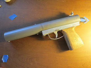
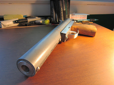
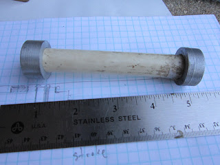
The result was a nice single shot pistol.
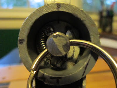
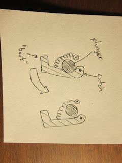
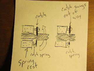
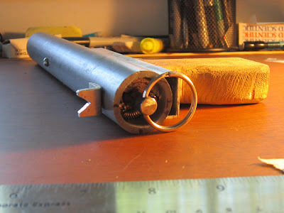
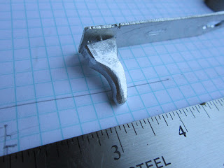
In the next one, you can sort of see the catch. I don't know if this type of catch has caught on yet or not, but a while ago, everyone still used clothespin catches. This catch is simple and dead reliable. A metal plate is just pulled inwards towards the plunger rod by the small spring. Pulling the trigger drives a wedge between the frame and the boot of the catch, pushing it out of the notch in the plunger rod.
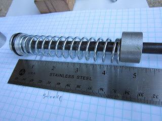
Here is the plunger head and rod. Both were machined by me of course, along with everything else. The plunger is 3/8 steel. The rod is rather heavy, but I used a nice spring and the ranges are great anyway. I have made aluminum rods before, but the catch notch rounds over and becomes unreliable.
Here is the plunger assembly. The spring rest on the rear later had a shoulder machined into it to center the spring. The mounts for the catch and catch spring are drilled and tapped into the rear of that piece.
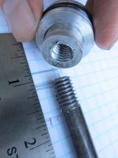
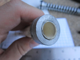
This is the barrel assembly. The forward center is recessed for the cpvc, so on one side I drilled it 17/64 for a dart, and on the other, 5/8 for the cpvc.
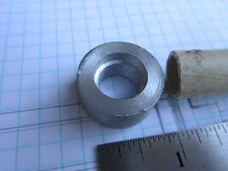
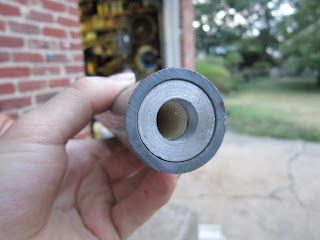
This is the rear center. It has one diameter turned that fits tightly into the 1" outer sheath, providing an airtight seal for the plunger tube to the rear. It was drilled through for the 5/8 cpvc, so that it could be coated with sealer and stay secure.
The barrel and the plunger all fit into 1" pvc, which for the purposes of explanation, I will call the upper receiver. This 1" PVC acts as the plunger tube and barrel sheath. It also provides the mounting points for the pieces.
The lower receiver...
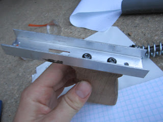
Not much to look at. The grip is screwed on. I replaced those pictures screws with flatheads for the trigger plate to pass over.
Trigger and trigger plate. In this picture, the original mounting rivet was falling out. I re-drilled and tapped the hole for a small machine screw.
The business end. From dead on, you don't see the cpvc.
Other notes
All the centering pieces were drilled and tapped to mount to the 1" PVC. You can see all the screws along the top and bottom of the upper receiver.
The "sight" at the rear is held on by one of the same bolts that goes into the spring rest.
If you look at this picture again, you see the lug about midway, just where the lower receiver starts. This is 2 pieces of PVC solvent welded on. It gives a good spot for the lower receiver to attach.
If anyone wants more detail, please ask. I didn't make this a real writeup as you need a lathe to make most of the parts. From all the draconian measures that I see going on around here, I assume many of the users are about 12, and don't have lathes. But once again, if you would like more info, just ask.
Ranges haven't been officially measured. Shooting level, it breaks 50 feet easy with a good snug dart.
I will hopefully have some videos of the range test and construction up within a few days. Bandwidth permitting.
Questions, comments, concerns?
Edited by Possemhunter, 23 July 2012 - 07:14 PM.