Introduction
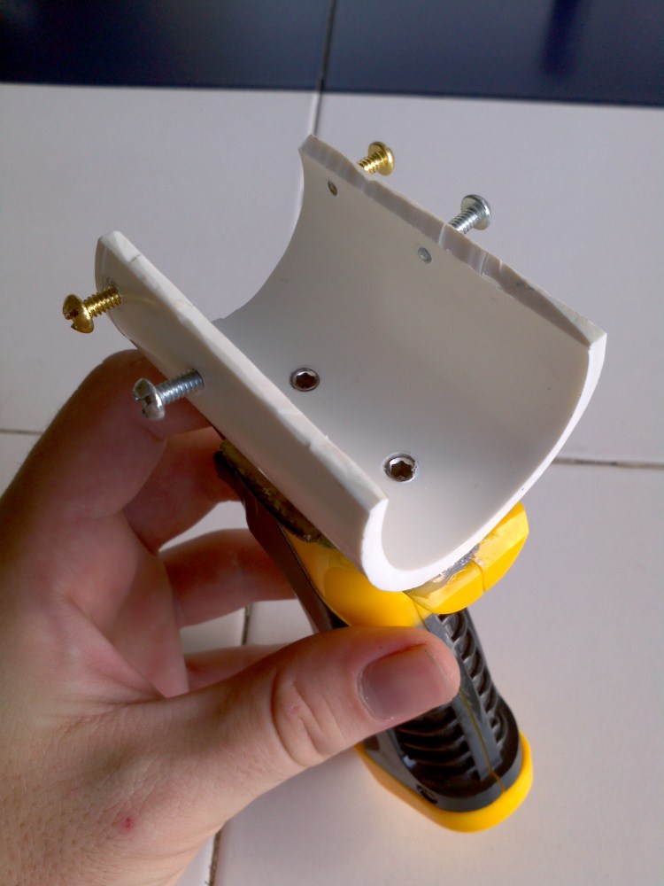
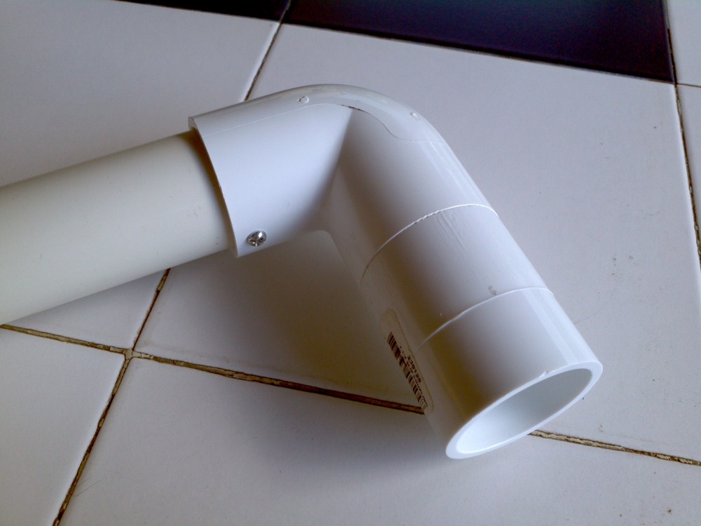
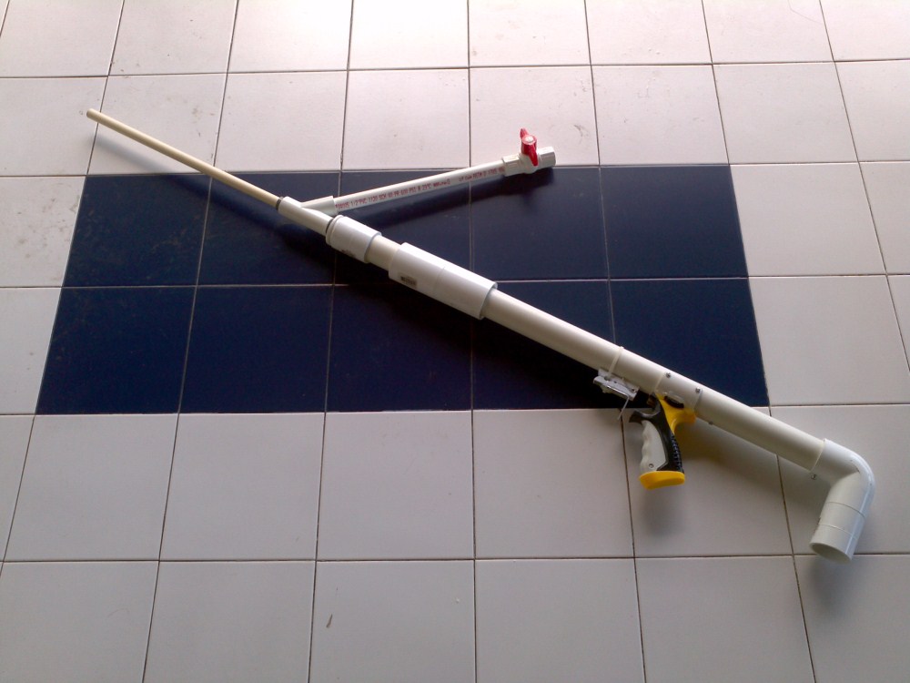
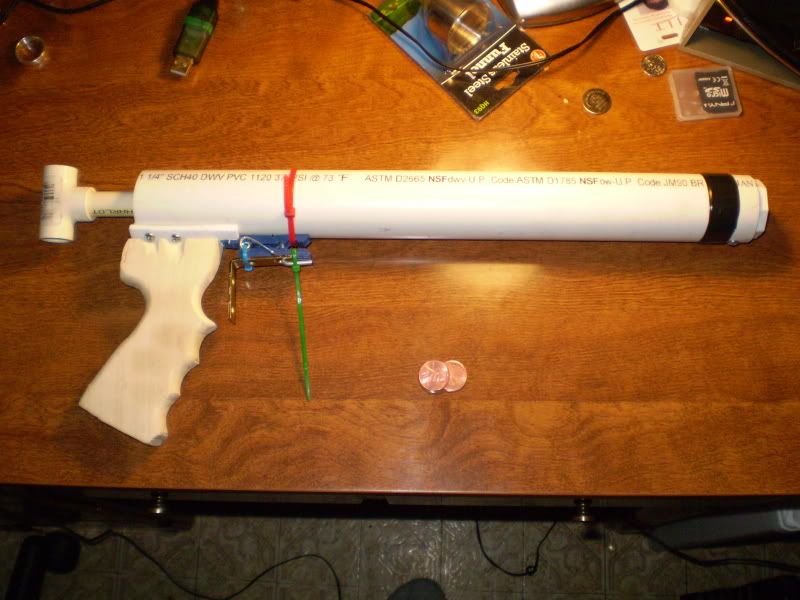
This blaster is a refinement of a refinement of a refinement of a refinement. At it's core, it is a derivative of Carbon's SNAP 7.5 Pump Crossbow, which is itself a refinement of his SNAP 2. I took the idea and ran with it. What sets the SNAP 7.5 style blasters apart from Stark's style (of which Nerfomania's design is a derivative) is that the priming action is in front of the catch, rather than behind. Though behind-catch-priming-blasters are much shorter, they are more complicated to build, requiring a lot of dremel cuts. The design I'm presenting in this writeup is very simple to build, requires no specialized parts, and delivers absolutely top-tier performance.
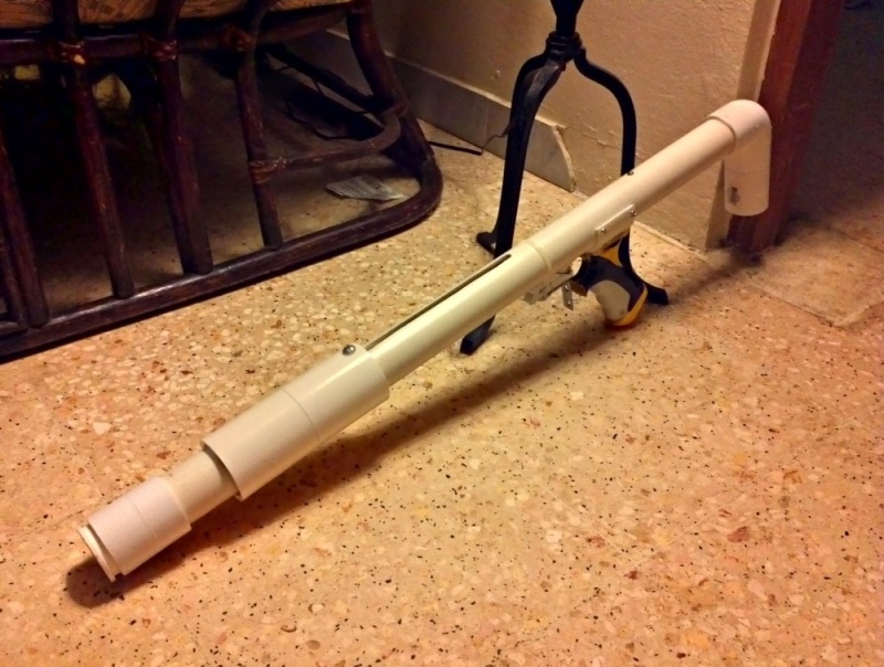
A couple of things to note before you start building one:
- This blaster is very long - the main body is 32", and the total length is 50" if you add a hopper and 16" barrel. If you are very short you will have trouble operating this blaster.
- This blaster has 6.5" of draw. This is detrimental to the long-term health of the spring, so you'll need to replace it every so often.
FYI, you can click on any of these pictures to get a full-sized view.
Materials
- Required
* Optional, but recommended
Tools
- Power drill
- Drill bits to go with it (1/16", 1/4", 1/2", etc)
* Tapping bits
- Rotary tool (dremel)
- Reinforced cutting disk
- Sanding bit
* Diamond cutting wheel (better for cutting plastics)
- Pipe cutter
* Three-sided drafter's ruler
Plunger rod
- 1/2" cpvc
- 3x 1/2" cpvc couplers
- 2x 1-1/4" OD 5/8" ID SAE washers
- epoxy putty
- PVC cement OR superglue
- [k26] spring
Plunger head <- don't feel obligated to follow this exact design
- 1-1/2" OD 1/4" ID (or smaller) rubber washer
- 1-1/4" OD 1/4" ID (or smaller) rubber washer
- 5/6" OD 1/4" ID (or smaller) rubber washer
- 1/4" bolt, 5/8" long
- 1/2" CPVC cap
- Silicone grease
Plunger tube and stock
- 1-1/4" sch40 PVC
- 2x 1-1/4" coupler
- 1/2" to 1-1/4" bushing
- 1-1/4" elbow
- 3/4" PVC endcap
- 3x 6-32 screw, 1/2" long (5/8" and 3/4" also works)
Trigger
- Heavy-duty clothespin
- 1-3/4" roofing nail
- Metal L bracket
- zip-ties
- Epoxy putty
- Hot glue
Priming handle
- 2x 1-1/2" PVC coupler
- 1/4" bolt, 5/8" long <- DO NOT USE BRASS OR ALUMINUM
- Tape or glue
Handle
- Donation blaster
- 1-1/2" PVC
- 1/4" set screws,
- 4x 6-32 screws, 1/2" long (3/8" or 1/4" are be better, but sort of difficult to find)
- Epoxy putty
- Hot glue
Construction
Here's an overview of the internals.

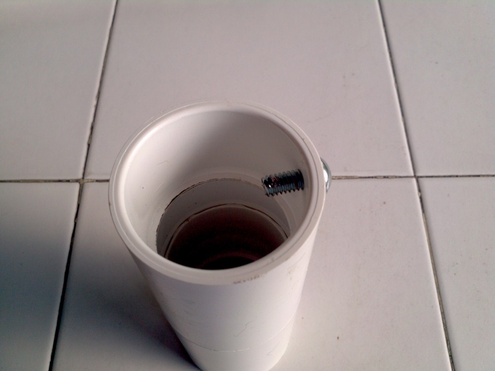
The key design feature of this blaster is the way the priming bolt works. Here's how it looks from the outside.
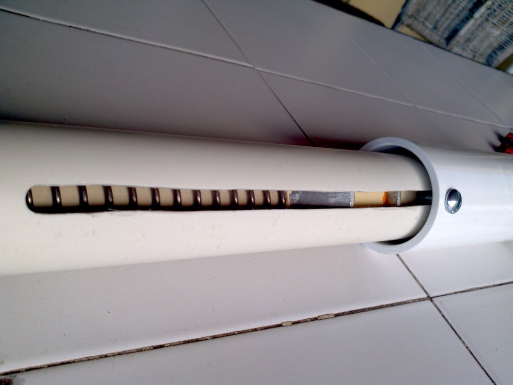
The bolt in the priming handle sticks into the slot, and catches on the front washer, allowing you to push back the entire mechanism. The clothespin trigger then catches on the rear washer. You may ask: why do it this way? After all, in my previous writeup, the priming bolt just pushed directly against the catch face, instead of this extra washer. There are several reasons I think this system is superior:
1) You don't have to cut a slot into the priming grip. This slot was doubly annoying because it neccessitated a 3rd 1-1/2" coupler to be added to the grip in order to give you enough space for your hand.
2) It gives you enough clearance to use a zip-tie to hold the clothespin in place. Mechanical fastening is far superior to adhesives.
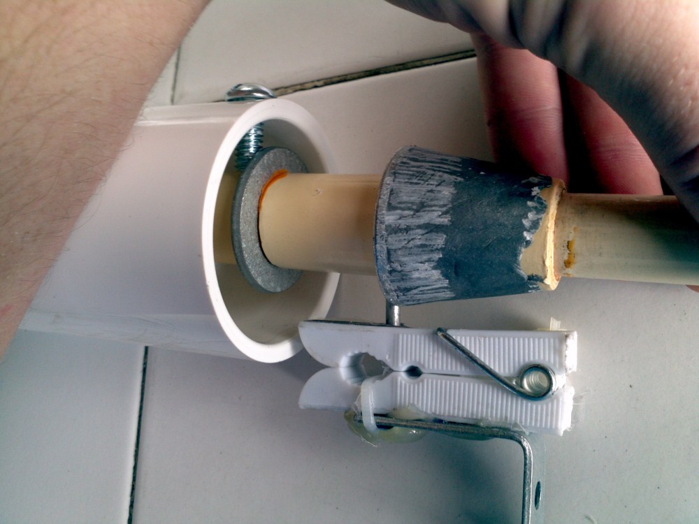
We're going to start with the plunger rod, since it's dimensions dictate the geometry of the blaster.

The catch faces are built from 5/8" SAE washers sandwiched between 1/2" couplers. Fit them together, and then use super glue or PVC cement to securely fasten them. There should be no "give" at all. Once you've glued them, build up your ramp using epoxy putty. You can also use a PVC ramp if you prefer.
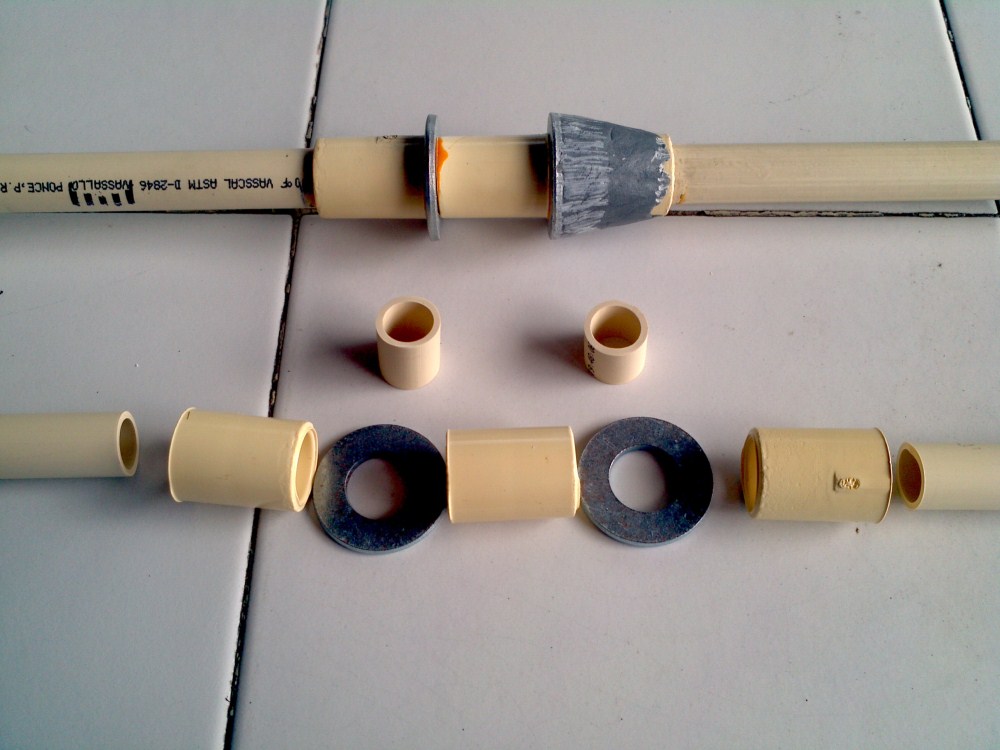
SAE washers are sometimes difficult to find, so there's an alternate way to do this. Use endcaps insead, and dril and tap 1/4" holes in them. You can then use any old 1-1/4" washer.

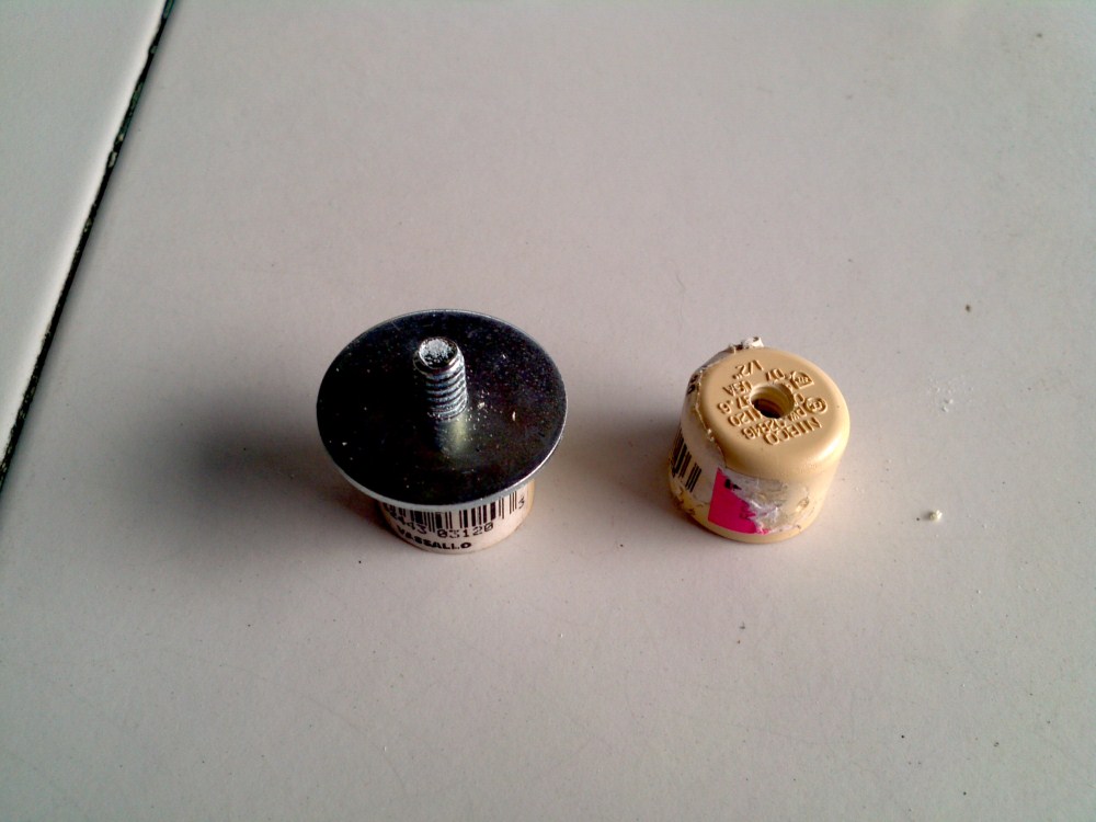
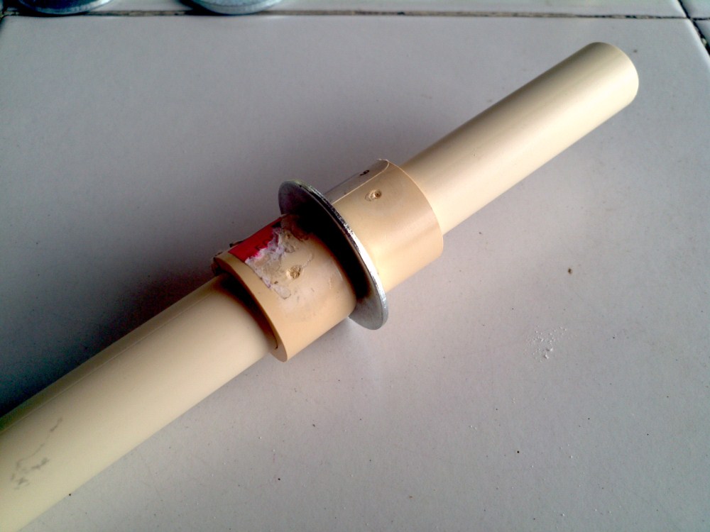
Might have to widen the washer hole first.

For a plunger head, I use a sandwhich of rubber washers, with a 1-1/4" metal washer to act as support. A 1-1/2" rubber washer acts as the main seal, and a 1-1/4" rubber washer sits behind that to prevent it from shearing against the metal support washer. In front of the 1-1/2" rubber washer, I use a small 5/8" washer, and I bind everything together using a 1/4" bolt. Most people use a second metal washer on the front, but I don't - I think the diameter of the bolt head is plenty wide. All this screws directly into a CPVC cap, and I usually add goop for support and seal. I use a 1/4" tap on the CPVC, and no nut. But if you don't have a tap, you can just drill a 1/4" hole through the CPVC cap, and then secure it using a nut. If you DO use a nut, consider flipping the direction of the bolt, so that the nut faces outward. This will let you adjust the tightness easily once the blaster is assembled. I couldn't find 1-1/4" metal washers with a 1/4" ID, so I just put them in a vice and drilled out the center. EZ PZ. Properly lubricated, this plunger head will give you a 100% seal.
There are lots of ways to build plunger heads, so don't feel obligated to use this design. Build whatever you're familiar with.
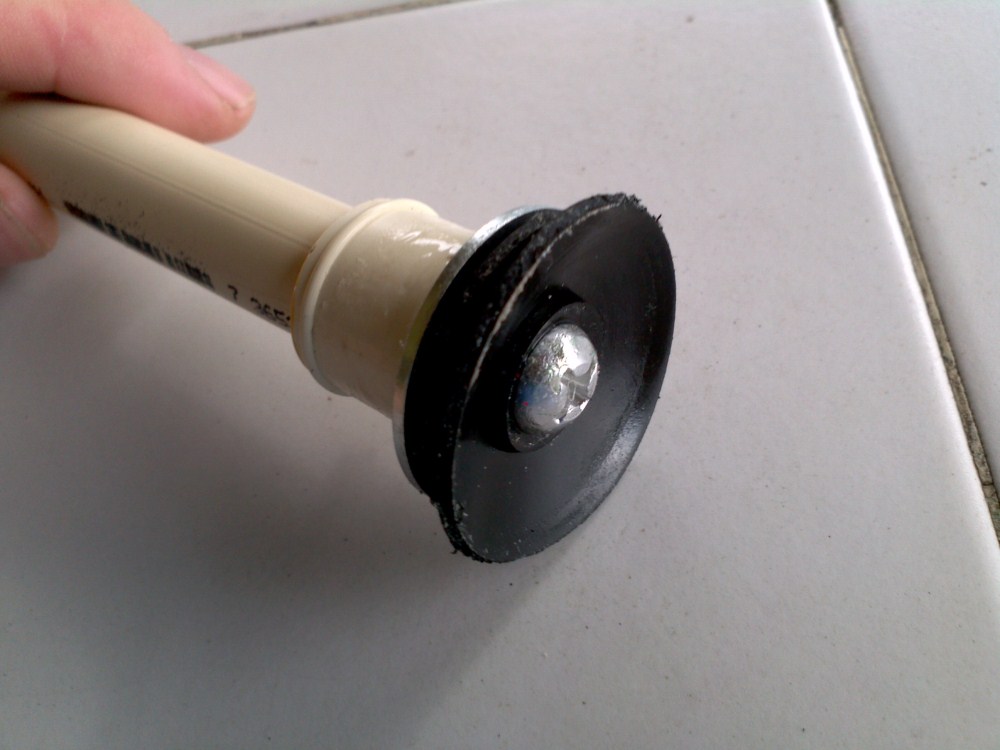
Next up is the spring rest. Use a 3/4" endcap, and drill out a 5/8" hole. That's problematically large, but there are serveral ways to do it. Most people just drill a 1/2" hole, and then widen it with a dremel. I acutally use a 5/8" drill bit, but it's too large to use in my drill. So I... improvise.

Let's get the measurements right before we glue anything together. The distance between the priming face and the plunger head coupler should be 7.5". All the shell cuts are going to depend on that presumption, and also the presumption that we are using a 1/4" bolt for priming (you can't ignore the width of the bold when making measurements!).

I'm also assuming the distance between the front of the plunger head (remember, the washer flares forward in the tube) and the rear of the plunger head coupler is 1.5". If your plunger head is significantly shorter or longer, it might screw up some of the dimensions. I have very loose tolerances built into all of these measurements, so it probably won't be an issue.

Let's take a look at the plunger tube. I highly suggest using a three-sided ruler for these, since you can lay it flat against the curve of the tube and make very straight lines. First, draw a centerline all the way down the side of the tube.

Next, mark the spot where the spot where the back of the coupler meets the plunger tube. For my design, I'm using a bushing and an external coupler, so that spot is just the very end of the plunger tube. But...

...if you use an internal coupler, such as with rork's SNAPbow mk5, that spot will be an 1.25" or so into the plunger tube. Set the coupler next to the plunger tube, and mark the plunger tube where the back edge of the coupler lies. All futher measurments are based on this mark, so get it right!
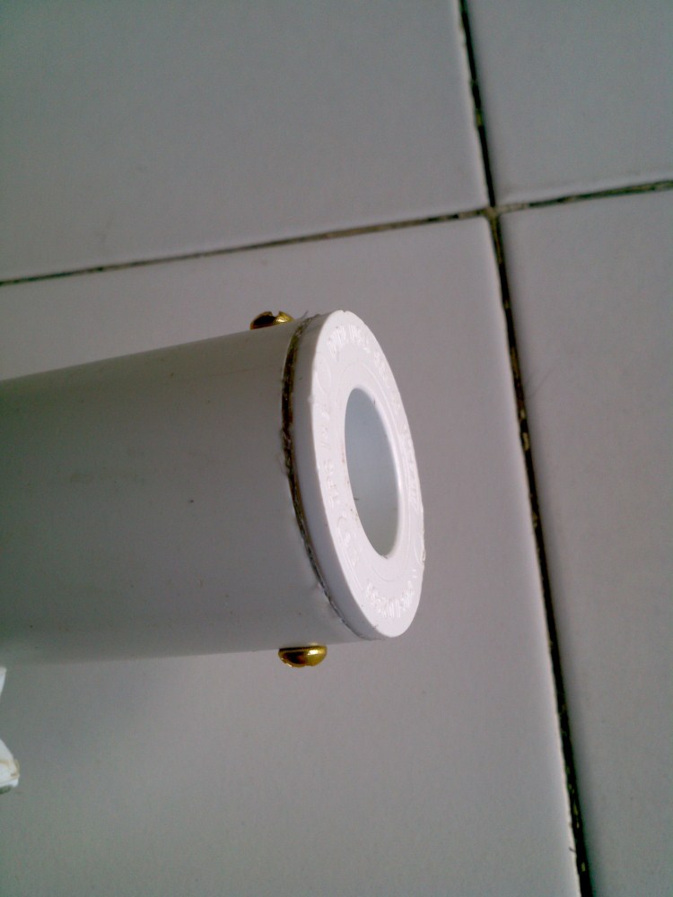
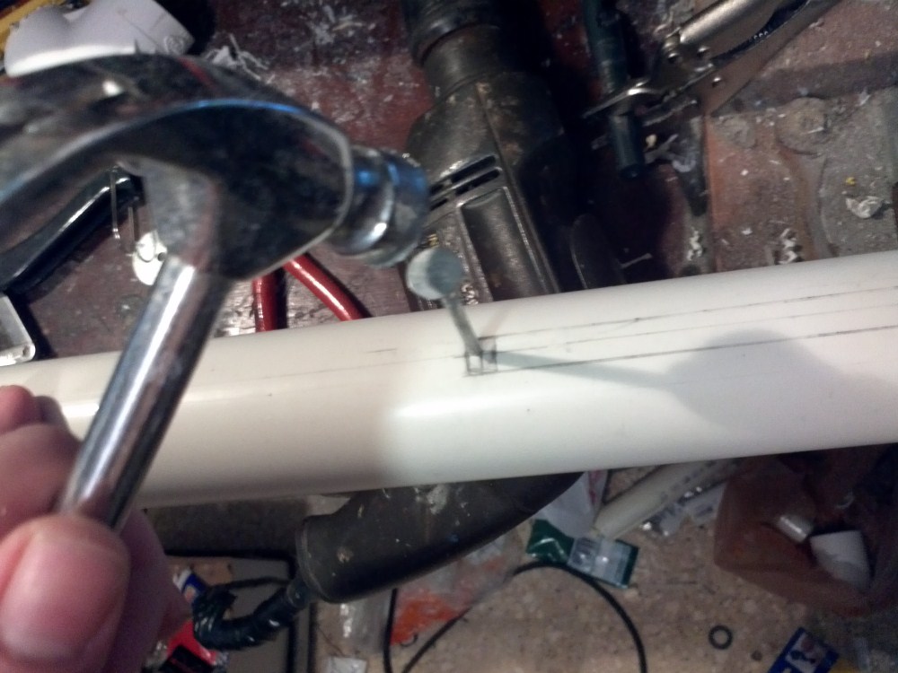
First, mark a spot 8" away from your front point. Then make another mark at 7.75". Make a third mark between those two - this is where you will drill with a 1/4" bit, to make the front of the slot. We're going through this rigamarol to ensure that the 1/4" bolt fits, and is properly positioned.

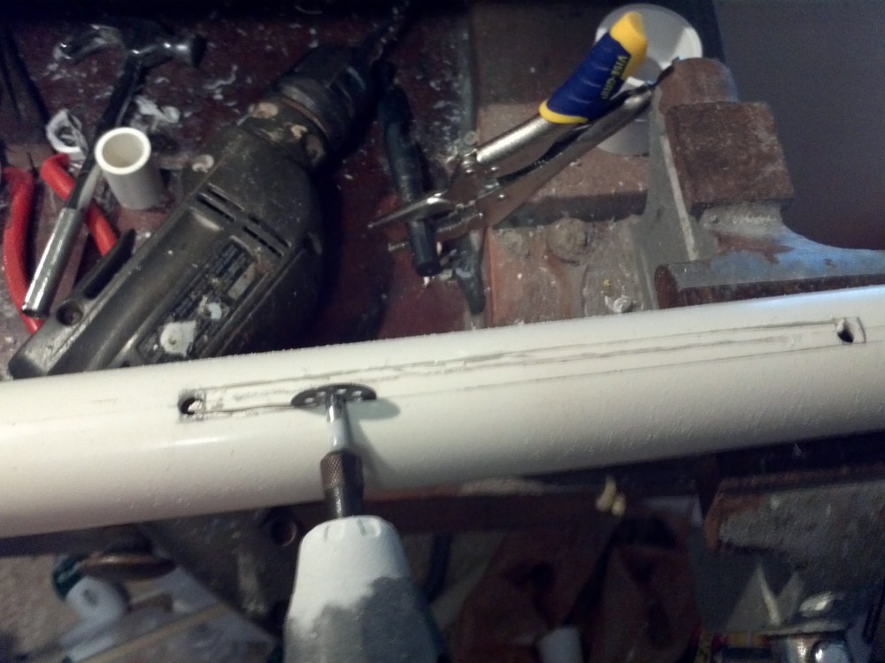
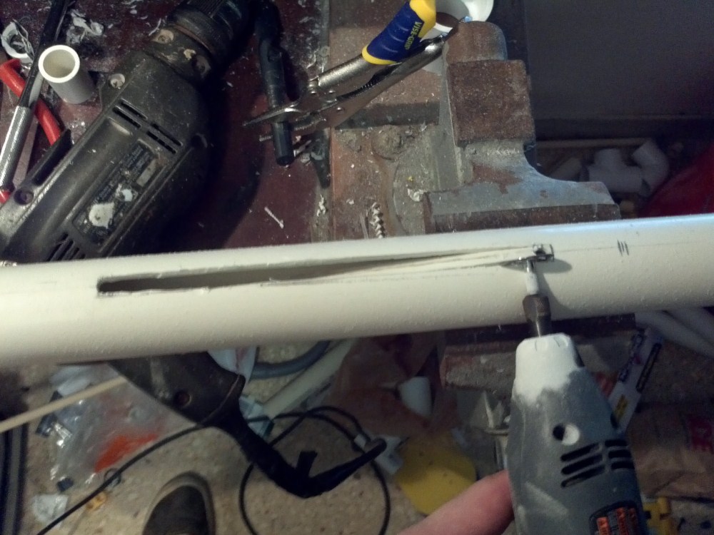
Next, we mark the rearmost point of the priming slot. It will be 7" away from the rearmost front slot mark. Make a second mark at the 6.75" mark, and then a third inbetween those. Finally, use your ruler to connect the outer edges of the hole marks to act as a guide for our dremel.


Next we mark the hole for the trigger. Grab your plunger rod, and place it up against the rearmost mark on the slots, and make a mark in front of the catchface.

The actually trigger hole is going to be on the opposite side. You COULD put it on this side, if you wanted. I initially wanted to do that, but the bolt head presses against your palm in that configuration.
In order to mark the other side accurately, I made a little guide tool. I cut off an edge of a 1-1/4" coupler, and then made marks on all the compass points. This slips snuggly onto the plunger tube, and allows me to accurately mark the opposite edge.


Edited by Daniel Beaver, 12 November 2011 - 09:05 PM.


