Jump to content


Highest Reputation Content


#353681 Constant Force spring blaster infodump

Posted by snakerbot on 22 May 2016 - 09:51 PM

IMG_3157.JPG

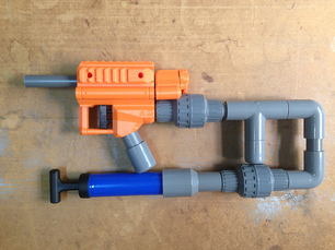
A while back I posted this in the homemades pictures thread.  In short, it was a blaster whose energy source was a constant force spring, like the kind used in Raider drums or your tape measure.  Specifically it was 9293K12.  For those who are not familiar, a constant force spring is a flat piece of metal wound in a coil around some sort of central shaft or bearing.  When you pull on the free end, the coil rotates around this shaft and unwinds.  Because pulling the free end farther only unwinds more of the spring, it doesn’t get any harder to pull as you pull it farther, hence the ‘constant force’ descriptor.


The origin of this experiment is several years ago when a poster on this forum (I can’t remember who it was or what the original context was) offhandedly mentioned constant force springs.  Fast forward several years and I have a job, disposable income, and boredom, and decide to give this a shot.  The original plan was to build a new blaster to run the experiment with, but I got lazy and retrofitted my extension spring rainbowpup instead.  Because of the nature of constant force springs they can really only be put into rainbowpup/eslt/whatever type blasters with plungers that are pulled instead of pushed. 


I’m going to drop some physics on you guys here.  I wasn’t sure exactly what spring to get, or how strong it should be.  Constant force springs really are a completely new area, so there are no “standard” springs or rules of thumb or anything.  Constant force springs don’t have a “spring constant” like compression or extension springs do.  So how to compare?  I didn’t come up with a good answer to this until much later.  What I eventually did was just guess and pick a spring whose draw force was about halfway (a little more actually) between the no-extension and full-extension force of the 9432k125 I found for my rainbowpup.  After buying the spring I realized that the best comparison was probably energy release.  The potential energy stored in a compression or extension spring is given by the equation E=0.5Kx^2 where E is the potential energy stored by the spring, K is the spring constant, and x is the displacement of the spring.  The potential energy stored in the K125 spring at the 6.5” of draw I use is therefore 65.4875lbf*in or 7.4J.  The potential energy at rest (I use no pre-extension) is 0J.  So the total energy released during firing (not all of which goes into the dart) is 7.4J-0J=7.4J.  So for the most equal comparison I should find a spring that can release 7.4J over 6.5in of travel.  Turns out by complete accident, I hit that on the nose with the spring I bought.


The potential energy of a constant force spring I couldn’t find online or in my machine design textbook, so I derived it.  (If someone finds a mistake in this result, please let me know, that might explain some things).  What I got was E=Fx where E is the energy released, F is the spring force, and x is the displacement.  So our total energy here is 68.9lbf*in or 7.78J. 

Note that the displacement term in the compression/extension spring is quadratic, while the displacement term for constant force springs is linear.  That means that for higher draws, the constant force spring falls behind in energy very quickly, but for this blaster/spring combo, I had almost exactly the same energy, so I moved forward with this.

spring energy graph.png


So theory over, let’s talk practical application.  The edge of the spring needs to line up with the plunger rod, because that’s where the free end comes off.  To accomplish this, I used a 1.5” pvc tee and carved it to the nines so I could mount the spring a little off to the side.  I drilled a hole through the tee and used sliding door bearings to hold the spring.  I ground them down so one edge of each could fit into the ID of the spring. 

IMG_3315.JPG

IMG_3309.JPG


For attaching the spring to the plunger rod, I used a section of ½” nylon rod (the same material used for the plunger rod).  One end was threaded to screw onto the end of a small stud with the priming disk on it.  The other end had a slot in it, into which I inserted the spring.  A small screw goes through a hole in the end of the spring (the spring comes like that) to affix the two together. 

IMG_3317.JPG

IMG_3311.JPG


Assembly is a bitch.  To get the spring into the tee, I had to hold it in place and slowly thread the bolt down through the tee, alternating between rotating the bolt a turn or two and then going back and rotating these nuts a turn or two.  Once that was done, I inserted the plunger extension into the front of the blaster body.

IMG_3322.JPG

That is where it sits at rest, so I had to stick my finger in the tee at the front and force it down towards the plunger rod. 

IMG_3323.JPG

Then I turned the plunger with my other hand to thread the two together. Not fun.

IMG_3327.JPG


So how does it shoot?  Not well.  I’m not sure of the exact reason now, but this blaster had trouble.  About one in five darts didn’t leave the barrel.  The ones that did didn’t seem to shoot as hard.  I don’t have a chronograph, but range tests show a clear drop off. I have a couple theories for why this could be.  First, while this spring is labelled as ‘constant force’, it isn’t like that, not quite.  Constant force springs take a small amount of travel before they reach their listed force.  I guess this is due to the shape of them or something.  I have a couple inches of pre-travel built into this setup, but maybe it isn’t enough.  Further, there is almost certainly more friction in this setup compared to an extension spring.  The bearings I used are a source of some of this, and the priming disk in the middle of the plunger rod is surely rubbing against the inside of the body because of the shape of the spring pushing it sideways.  There is also a possibility that the spring, which is 1in wide, is scraping on the inside of the front body of the blaster.  One final reason is that the process of disassembling this blaster and replacing the spring seems to have messed up the rod seal a little bit.  I’m not sure why, and it doesn't seem bad enough to account for all the problems I see.


I said in the pictures thread that “this is the weirdest thing ever”. What did I mean by that?  Well, it primes like nothing else I’ve ever used.  I’m not even sure how to describe it.  “Light” is almost right, but that isn’t really it.  I end up smashing the priming handle hard against its stops almost every time I prime it.  It’s like I begin to prime back and am expecting a certain amount of force based on how much resistance at has at the beginning, but then it throws me for a loop because that extra resistance doesn’t come.  I’m sure I could get used to it eventually, but it is pretty weird at first.


So, difficult to assemble, expensive ($10.83 for one spring!), weird to prime, and not shooting quite like you’d expect.  Are there any upsides?  I don’t know.  If you could find the right spring, and get the geometry correct (no grinding), you could make one of these that shot pretty well and maybe felt like it had a weaker prime, but I don’t consider that worth it.  Extension springs already have pretty light primes for how well they shoot, and I don’t see this offering enough advantages to overcome the disadvantages.  I’ll leave the blaster as-is for a little while if anyone wants more pictures or wants me to do any more tests, but I don’t see a good reason to keep it as it is forever.


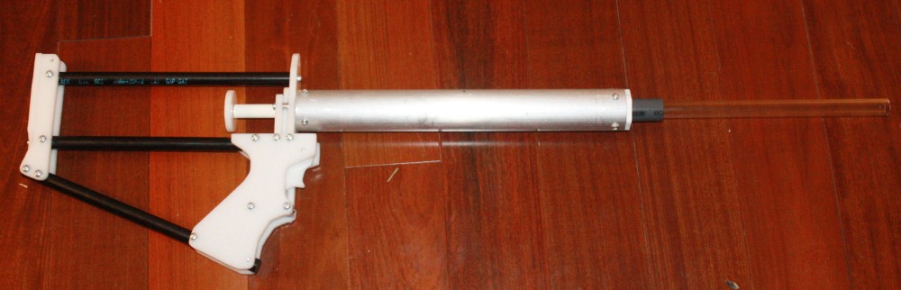
Crossposting additional pictures from the homemades pictures thread here, so it's all in one place.

IMG_3159.JPG

Not primed:

IMG_3160.JPG

Primed:

IMG_3161.JPG


  • 7


#358196 1995 Crossbow CAD Files

Posted by CaptainSlug on 24 February 2017 - 05:10 PM

I haven't modeled the springs yet. I'll add them to the set soonish, then make the STL files available.


STEP 214 Format: http://captainslug.c.../Crossbow95.zip (2.6mb)


Stitched Shell Scan: http://captainslug.c...erf/cb95_s1.jpg

Exterior DXF: http://captainslug.c.../Crossbow95.dxf

Cutaway DXF: http://captainslug.c...bow95inside.dxf

c95_11.jpg

c95_12.jpg

The internal parts are 100% measurement accurate. The shell however isn't exactly dimensionally perfect. It's been altered for improved strength and more compatibility with 3D printing (hopefully).


  • 6


#354914 FDL-1: Fully 3D Printed Robotic Blaster

Posted by jkovarovics on 10 July 2016 - 09:39 AM

Hey everyone,


I wanted to introduce you guys to the FDL-1. Some of you may have seen a prototype version in a Drac video a few months back and anyone who was at DartCon during NvZ this year probably saw it in person. It's a fully 3D printed Mega blaster controlled via an Arduino like microcontroller running brushless motors. I've also open sourced it so people can print their own if they're up to the challenge. I have a website setup with a webshop. It's http://www.fdl1.com. If this perks your interest, check it out, there are more pics and info there. There are also links to the Thingiverse page and Facebook page.


Just to be clear, I am not here to market the FDL-1. If you want to buy something, cool, but I mostly want to show this to Nerfhaven. I entered the Nerf community from the maker world. I had no idea the stuff you guys were making. My first war was a Nerf culture shock. There was 3D printing all over the place, blasters mashed together, painted, hydro dipped, the works. I was impressed to say the least. The point being, I had never had anyone tell me you couldn't or shouldn't print an entire blaster or use brushless motors or make the thing robotic so I just did it. I spent over a year revising the entire design over and over based on my experiences of using it in the office then on the field. In the maker world, bigger is almost always better so I went with Megas. I also hadn't seen a flywheel mega blaster released by Nerf at the time so I took that on as a challenge. Anyway, I posted about this on reddit a few months back and got slammed with criticism. I just came on here looking for a NIC blaster design for NomNE and saw someone talking about 3D printing a full blaster. Some of the first comments were you shouldn't and that you can't print flywheels. It pains me every time I see those responses. In the maker world we ask ourselves what if? I feel like the NIC does a lot of asking why. I never asked myself why would I print an entire blaster, I just asked myself what if I did and did it. What if I took the motors off my drone and stuck them on there? What if I want to operate the thing remotely? Use a microcontroller. What if a revolver is clunky? Load it from the back with a button to advance it and throw in an IR sensor so it doesn't dry fire empty chambers. All what ifs. The NIC is full of brilliant minds and makers at heart. I'd hate to see a cool design not created or a mod not done because someone asked you why you would do it or told you it was impossible. Just try it.


Anyway, here's a pic. Let me know what you guys think. My next design will be mag fed before that comes up. Nerf, make, print on


aPLCSN4.jpg


  • 5


#354210 Armageddon XVII: SoCal's Largest NIC War (2016)

Posted by Ryan201821 on 14 June 2016 - 10:34 PM

Great war. It's been 7 years since I've been to a 'Geddon. It was cool seeing a bunch of people I haven't seen in years, and also meeting a bunch of new people I've never met. The war location is excellent for a war this size. I especially admire the perfect symmetry allowing different games to be set up easily and accurately with little effort. Thanks to Zeke for putting up with everyone's bullshit for the weekend, and the time and cost that goes into hosting a nerf war, especially one this size. 


Things I liked:

  • Death clicker gametype is a perfect mashup of Deathmatch and Meat-Grinder. I need to get some mechanical counters.
  • U3 trains
  • Other general trains that were rollin'
  • Rock Mode, of couse.
  • I took a nice cold one.
  • Double ESLT is super effective, still...The blowgun is the perfect attachment for shooting little kids, or rushing fools while making poop sounds.
  • Little kids who were smarter than a lot of the older people.
  • Lots of ideas for potential future projects to revolutionize nerf once again.
  • Weather 

Things that could've been better:

  • Staging area was too close to field of play. Maybe we should just tell people expect to be shot at all times, within the gated area. (i.e. wear safety glasses)
  • Decent cover, but a couple smaller mobstacles in the more open areas would've made it perfect.
  • Not having to fly on a plane to get there.

Things that need to change:


  • FVJ darts, and other not-even-close-to-soft domes = not nerf. These things are straight rocks, yo. I saw some pretty nasty damage to some people from these darts and at points it was generally frightening to walk into certain situations. I think this was also amplified by the most likely over-powered blasters they were using. 
  • Loudspeaker would be a nice addition. Sometimes it was difficult to wrangle people to the next game. Especially since none of us were very good at yelling.
  • Darts in general. Maybe by this time next year we'll finally have the end-all solution.


I definitely plan on going next year. Sorry East Coast, but it is better than Apoc.


  • 5


#357858 Good wills and Thrift stores in New York City

Posted by ToadBrews on 06 February 2017 - 02:56 PM

You have a massive sense of entitlement and you expect everyone else to do your research for you. Neither of those will help you get ahead in this hobby, or in life. It's hilarious you're upset a random goodwill employee didn't know how much a legendfire costs when you, someone who has an interest in foam blasters, also had no idea. No one forced you to make a bad purchase. Nobody ripped you off. You picked up an item with a price tag on it, the cashier charged you the amount on the price tag, and you took the item home. Then when they gave you a store credit to make up the difference (something which was a courtesy to you and theynhave no legal or ethical obligation to do) you went on the internet and racially profiled them and called the manager a bitch. The problem here is you.


  • 4


#357155 Homemades Picture Thread

Posted by EocDragon on 14 December 2016 - 08:02 PM

These are basically homemades:

O1UtME8.jpg


So I've been collecting Berserkers for a while because they have that sweet, sweet 4B tank inside. Berserker shells are hot garbage though, so I never did anything with the dozen or so that I have, since I don't want to just chop the front off of the shell and call it a day and I also don't want to spend 6 hours dremeling the fuck out of some other, better shell for each one and every one.


I do have a 3D printer though, so rather than remake all of the files for my springer homemades that I lost when my hard drive crashed last year, I procrastinated and made these instead. They're essentially 3D printed shells specifically for the 2nd Gen Berserker tanks so that I can print them over them the course of a day and then drop the tank in with minimal effort. Everything is mechanically fastened so the whole thing comes apart to maintain the tank or replace broken parts if that happens. 


Ranges are unplugged 2nd Gen 4B ranges. I might eventually make a version for the 1st Gen tanks, but those Berserkers are less common (fun fact, did you know that there are 5 variants with the 2nd Gen tank to the one original variant with the 1st Gen?). For now they're pretty easy to make loaners for wars (it's harder for the kids to break unplugged air blasters).


  • 4


#356160 JSPB3D

Posted by 3DBBQ on 08 October 2016 - 04:07 AM

jspb-3d-astm-free_orig.jpg

Introduce:

Hi! This is my new work, part of the use of 3D printing, it is very simple production,
just need to put it together , glue together, and you can change the style you want.
 
This model looks like some of the features of the past works, is not the same place? 
it has reserved some air road,using PU soft tube to connection, in addition to the RSCB Clip can be added,
the future can also connect another pump to push the clip inside darts.
 
The second pump push the darts inside the clip videos:
JSPB Pro2 does not need to muzzle down to load, JSPB Pro2 can continue shooting.
 
 
Pump air in to the Clip inside the darts to precision position is not easy, 
they must create an air escape,to prevent the continuous emission of darts.
 

3DSTL Files : 

https://drive.google...N00?usp=sharing

JSPB3D SCH40 core.STL
JSPB3D SCH40 breech ring.STL

JSPB3D trigger.STL

JSPB3D guard.STL
Breech block.STL
lock plate.STL


3D Printr settings:
I used the layer of 0.25mm and 0.6mm of the nozzle,
Basically, this model is fairly easy to print and does not require supporting materials.
 
Specification:
In Asia to get CPVC SCH40 is difficult, here are the use of CNS specifications,
Later I ordered the HERSHY CPVC4120 SCH40 on the Internet ,so I actually tested it
 
Tolerance issues:
Too tight part can use the hammer to knock into, too loose place can increase the thickness with PTFE TAPE,
Model tube through the place where most of the design groove, you can also plug O-Ring,
There is another way is to use screws to fix.


Part list:

j3d-white-up_2_orig.jpg

ABS rod  Φ5mm
SCH40 1/2"
SCH40 3/4"
PETG 1/2"
CHECK VALVE 1/2"  x2
PU-Tube 8X12mm 
OS   3/4"
1/2" Elbow   x2
3/4" Cap 
Pump
7X1.9  O-Ring
16X1.9  O-Ring
24X16X2 Rubber washer
Screws 5/32 X 1/4
Screws 5/32 X 5/8
AB Glue

Option:
1/2"  Tee 
1/2" Cap
Cable tie 
PTFE tape
Air flow direction:


j3d-white-up-air_orig.jpg

using screwdriver and a hammer to chisel a path to add more airway:


airpath_1_orig.jpg


img-1675.jpg?306


  • 4


#355527 Modification and Paintjob Pictures

Posted by Ryan201821 on 13 August 2016 - 11:24 PM

P10206811-1.jpg


  • 4


#354691 Plusbow Rev. 3

Posted by CaptainSlug on 30 June 2016 - 08:48 AM

bow3_007.jpg


Plusbow Rev.3 Guide


Instructables Mirror


Design Goals

  • Reduce Part count
  • Two Options for Plunger tubes and Plungers (+bow or 2-11)
  • Omni-directional catch
  • Spring guide to remove "serpentine" behavior
  • Ease of dis-assembly
  • Limit screws to two lengths (1/2" and 1-1/2")
  • "Check Valve" Plunger head
  • Use of extension springs or rubber bands for catch (multiple configurations possible)
  • "Ultra-Compressible" O-Rings
  • NO MORE INTERNAL CUTS, that means no pilot holes, no feeding a scroll saw blade through a pilot hole. Every cut can be done with a scroll saw or a band saw.

Total Build cost: $70 (for one plunger tube type)

Sunk Cost per Plusbow: $25


Thanks to: Splitlip, Aeromech, Ryan McNumbers, Groove, CrankyMonkey, VACC, and TED


  • 4


#354638 Looking back at 14 years in the LGLF...

Posted by Langley on 28 June 2016 - 02:25 PM

14 years ago today, I met up with my friend Fred from highschool and we modified a nerf blaster, committed an act of petty larceny, and signed up for a Geocities account.  The blaster was actually a Super Soaker XP 150 modified to shoot nerf darts, the theft was a garden gnome from the garage-sale addicted hoarder down the street, and the Geocities account was for the LGLF homepage.  5 weeks later we joined up with one of my nephews (Left Nut) and found ourselves at the first annual Apocalypse nerf war, where we met Vacc and Spoon (the original founders of NerfHaven), One Man Clan, and the members of the Lawn Chair Mafia nerf clan.  A couple of weeks after that we hosted our own war, and called it GnomeFEST.  We were the baddest group of toy-gun-toting dorks in New Jersey.
 
Langly.JPG
 
Over the next few years I met Talio and we all went on a road trip down to the D.C. area to nerf with Crankymonky and Groove (Edit: yes, and THIRST.).  Shortly after that, Hasbro sent a designer and an engineer out to a GnomeFEST to meet us, and they recruited Talio and One Man Clan into an early version of their Nerf Ambassador program.  The designer from Hasbro is still working there, leading the team on the Rebelle line.  We nerfed around Philadelphia and some paintball field in bumfuck Delaware, and had a few more Apocs and GnomeFESTS.  Around 2005 One Man Clan agreed to pick up some kid from Hoboken who he'd never met on the way to a war.  They sat in uncomfortable silence for about an hour as OMC wondered how this guy was going to load a nerf gun with only one arm.  That guy was JLego, and he turned out to be the fastest most impossible to hit nerfer at that event.  We met lots of other people over the years, and some drifted away or stopped nerfing, including Fred, and then eventually, me. 
 
When I came back in early 2008 after a two year hiatus, I reconnected with Talio and JLego, and they introduced me to some new guy named Splitlip.  We all agreed to carpool down to a DCNO later that spring, and in an alcohol fueled surge of collective nostalgia, the four of us decided to re-boot the LGLF. A month later Talio joined the Mag7 in the worst act of betrayal on American soil since Benedict Arnold.  But that was okay, because we would add Muttonchops in 2009 and Gears in 2010.  Our old allies Crankymonky and Groove would both join us in 2011, and (though he'll deny it) TED joined in around 2012.
 
Over the years we traveled all over the east coast, to Maryland and Virginia, Philadelphia, Pittsburgh, Toronto and Chicago.  We went to Penn State for Humans vs Zombies, and some of us flew out for Armageddon in Los Angeles.  We made a lot of friends on those trips, and even more came out to visit us every year at Apoc.  We met the Sex Dwarves of Pittsburgh, and the U3 and Rainbow Clans from Chicago.  We played with nerfers from Ohio, Minnesota, Oregon, Washington, Georgia and Florida.  We helped host Geddon, DCNOs, ECNOs and NENOs.  We ate Hasbro's Pizza and we drank their beer.  We busted UIN13s balls, hit on Lord Draconical's girlfriend and pooped in Forsaken Angel's toilet.
 
I got a little carried away there.  What was I saying? Oh yeah. 
 
I love this clan, and the people who are in it.  It's been an incredible 14 year journey and I wouldn't trade it for anything.  I know we're scattered all over the country now, and I'm well past my nerf expiration date, but I'll keep going if you do.  Thanks guys. 
 
-Langley
 
GroupShot.jpg
10371602_10103866900172939_971413470646675538_n.jpg
10356689_10104346792654559_548979891915000760_n.jpg
1420585665-316199-5-lglf.jpg
GLHF.jpg
 
There are some more photos I dug up in this album on facebook: https://www.facebook...59315644&type=3
  • 4


#354211 Armageddon XVII: SoCal's Largest NIC War (2016)

Posted by Langley on 14 June 2016 - 10:46 PM

  • Loudspeaker would be a nice addition. Sometimes it was difficult to wrangle people to the next game. Especially since none of us were very good at yelling.


I appreciate the euphemism, but 'loud asshole' is the proper nomenclature.  I'll try and make it next year. 


  • 4


#352868 Stryfe Mag Release Extender

Posted by Cappucino on 19 April 2016 - 05:08 PM

Hi Folks! Today I wanted to get an extended mag release button for my stryfe, but I didn't want to pay a lot for shipping from Hobby Mods. So I made a nice little homemade one! I'm pretty sure someone has done this, but I wanted this to be here for reference. So I present to you, my homemade Stryfe extended mag release button. (I'm not sure if you can do this with other stryfe style mag release blasters, but I'll check on that.)


So this is what mag release looks like.


IMG_5717.JPG


So Start out with your Stock mag release stryfe

IMG_5718.JPG


Open up your stryfe. (This stryfe is my old modded one)

IMG_5719.JPG


We will be focusing on this area right here. This is the mag release.

IMG_5720.JPG


Take out that screw and take these two pieces out.

IMG_5721.JPG


We do not need this piece. You can put this in your extra parts bin.

IMG_5722.JPG


Now take this Mechanical Dart Lock out.

IMG_5723.JPG


This is what it looks like.

IMG_5726.JPG


Remove the spring on it. And Trash or keep it. 

IMG_5728.JPG


Now you are left with this.

IMG_5730.JPG


Cut this small nub off with a dremel and some other cutting tool. 

IMG_5732.JPG


Now grab the other piece of the mag release we had before.

IMG_5734.JPG


Add your choice of adhesive to the green spot. (I used hot glue, but you can use something stronger)

IMG_5737.JPG


This is what it should look like after

IMG_5741.JPG


Now place it back into the stryfe

IMG_5742.JPG


Put the screw back on

IMG_5743.JPG


Finally, put the other half of the shell back on and screw the stryfe back together.

IMG_5744.JPG


And there we have it, the homemade, cheap extended mag release! This is my first writeup, so I would like any kind of feedback. Thank You!

Attached Thumbnails

  • IMG_5737.JPG
  • IMG_5741.JPG

  • 4


#361992 my custom nerf loadout

Posted by Ice Nine on 19 November 2017 - 07:23 PM

This is the most beautiful thread posted to NerfHaven in several years. I'm locking it so no one can sully its beauty.


  • 3


#360588 Muzzle loading 17th Century Pistol

Posted by Justin Andrews on 15 June 2017 - 03:47 AM

17th Century English Lock Cavalry Pistol (field test prototype).
LARP safe foam firing firelock.

Based on an existing English (or Doglock) pistol, this was a large pistol commonly used by cavalrymen.

The lock is a fully working copy of a flint lock, with both full and half cock positions, as well as a safety at half cock which makes it hard (though not impossible) to fire the pistol, in addition the external sear is movable and can be used to retain the cock.

Fires the same foam ball ammunition as the Larpquebus® with a range of around 9-10 meters, and well under the 1 joule limit (required in the UK to ensure the blaster does not fall under the legal category of lethally barrelled!)

Otherwise its the same general operation as the Muzzle loading Musket (Larpquebus) I posted here a while ago.


Attached Thumbnails

  • 1.jpg
  • 2.jpg
  • 3.jpg

  • 3


#358714 THIS one simple design will have you in TEARS...

Posted by Chanclas on 22 March 2017 - 11:54 PM

Hello, everyone! I have been dead for a long time on here. I'm back for today because I couldn't keep this a secret any longer. THIS PROJECT IS ALMOST COMPLETE, this is not a full write-up. It loads and fires but has a bad seal. I can fix that but I don't have time--I haven't touched the project or even the tools in many months. That's why I'm just gonna show you my thing and let you do what you want with it.


No official name but let's call it the Sex Pistol for now. First person to perfect it gets to rename it. But do you really want to?

gun one.jpg gun two.jpg


The biggest inspiration was the Multiple Orgasm, by makeitgo. The day I saw that thread was the day I finally had what I needed to make the SP. Let me tell you, I had some far out ideas about how to make a mag-fed pistol, none of them realistic.


The Sex Pistol is just a like a real pistol. You can load a magazine in the handle, cock the slide back, slide returns forward, you pull the trigger, dart leaves the barrel. It's got some weight to it, feels good in the hand, and is 12" long.

ANIMATION of sexy 1st design


Of course, nothing stays the same. I've changed some moving parts when I found out that the real world isn't the same as the 3D model world.

VIDEO of sexy man cocking and dry-firing the Sex Pistol


The best change I made was the way I made the handle and the magazines. For the handle, I used a heat gun to soften the 1-1/4" PVC and then shoved two lengths of 1/2" PVC inside, side by side, to "spread" it from the inside. While it cooled, I pressed it between two wooden boards to flatten the sides a bit. The result is so comfy and strong. For the magazines, you can do the same with 1" thin-wall PVC, with two lengths of 1/2" CPVC inside--OR you can shove the softened 1" pipe inside the handle you already made. As it cools, wiggle it around and slide it in and out--this will keep it from hardening and getting stuck. You can cool the pipe faster by spraying water on it. ALL OF THIS SHOULD BE DONE IN A VENTILATED AREA--some, like Captain Slug, would suggest that you also wear some kind of respiratory protection.


The coolest change is the way the slide can be locked in the cocked position to allow for easy magazine swap. This came about from a design change where the magazine would be "closed" at the top which wouldn't allow the dart-retainer-lips-things to spread around the bolt. I like this feature, even if the magazine lips are open and allow the bolt to pass through. You wouldn't need this slide-lock if you decide not to add the slide return spring, which is on the barrel and pushes the slide forward after being cocked. But why wouldn't you want that?! It's so cool!

VIDEO of sexy man poppin' and lockin'


The most difficult change was the damn "mobile" catch and trigger assembly. The first reason for this change was that the plunger and catch would slide back in the plunger tube, instead of firing, when the trigger was pulled. Only way to stop that was to hold the slide forward with your free hand, which is dumb. The solution was to come up with a trigger that pushed up or forward or both. I went with the one in the middle on the left side of the animated image linked below. The trigger is a length of 1/2" CPVC, with a hole cut out to allow for the gray flexible trigger-catch-pusher-thing. The gray strip is just thin metal with a rounded nub of plastic glued on it.

ANIMATION of trigger designs


The second reason was that the simple 3-layer catch shown in the animation was not easily fabricated with my sexy Dremel and wasn't strong enough. The result is a big ugly thing but I believe it is an original concept. Imagine the plunger entering from the right, catching on the ring in the middle. The trigger pushes up on the ring, which is bonded to, and flexes up on, a strip of CPVC extending from the CPVC section that is the left end of the catch.

20151207_175054_HDR.jpg


There are a few things I designed that I'm pretty sure are new ideas. Dammit, I give up, I'll just have to get better pictures tomorrow. I haven't updated the model so you won't like it if you see it. Even if I wanted to, my computer is too old to be sexy and can't even install AutoCAD properly.


A few little notes:

-Magazines can be made any length but mine is currently long enough for 14 darts

-Magazines can fit darts up to 1-1/4" in length

-Ranges aren't expected to be impressive, even with a perfect seal. Current stroke is 2-3/4", I believe, which is pathetic, I know. That's just how it is, unless you make the pistol longer.

-I know it's big but it's also smaller than you think.

-Here's a Google Drive folder with all the pictures and videos and maybe the .dwg model file thing.

-Another fitting name for this pistol is Pillow Talk. I was gonna say something gross that rhymes with "eremature pjaculation" but I didn't. Also, it's full unofficial name is Sex Pistol: Experimental Reloading Mechanism.


One more thing. When I was about halfway done building the first crappy prototype that barely held together for a few days, I emailed the guys that print and sell ESLTs and PullSCRTs. They said they'd print any design if you were willing to pay for it. The price they gave me wasn't sexy and they said my model wasn't printable. That's fine, no hard feelings. I had laughs and tears working on this. Thank you guys for not stealing my concept and making it better and printable.


Okay, I'm spent.


  • 3


#358025 A hardly ideal +bow

Posted by Hardly Ideal on 17 February 2017 - 03:59 PM

I've wanted to make a +bow for years- about since it first came out- but I could never quite get it to work. The materials and tools required were prohibitively expensive, and my brother and I had already collected a whole galaxy of comparable modified blasters in the meantime. After a string of other failures and disappointments, the whole idea of homemades kind of dropped off my radar.


Fast forward to 2016. At work, I've been tasked with feeding and watering our new-ish 3D printer, which we got it for making prototypes, quick repair parts, and custom tool caddies. My boss told me to "get good with the thing" and "I expect to see cool things on your desk soon."


He's a great guy, but you should really be careful what you wish for.


F7SX5T9IXUQAFY3.LARGE.jpg


Not the greatest +bow in the world, but it's mine. And aside from a janky Snapbow-like thing that scored maybe one hit before ruining itself, I'd call this my first practical homemade.

  • Aside from the plunger body, spring, and fasteners, everything is 3D-printed.
  • Largely identical to CaptainSlug's original except for some minor tweaks.
  • Embellished the panels and grip with triangular cutouts. I kind of have a thing for triangles these days.
  • Three levels of draw like the original design, but with an original plunger head. I can never get the right rubber seals, but I've managed to get a solid plastic plunger head at just the right diameter. Less than ideal, but I'm not about to question anything that actually works.
  • Customized plunger rod grip. The original was a bit too big and sharp for my liking
  • Built-in dart holder. I thought about including add-on rails, but I almost never use those except for dart holders. So for a scratch build like this, I decided to just integrate it from the start.

I've yet to use it in an actual game, but the +bow already feels like a very versatile platform. So naturally, this is a work-in-progress.


FRXZ411IY0FZ4SZ.LARGE.jpg


Stage 01

  • All the important parts out of the printer. A few tweaks to the original to account for taste and oversights on my part.
  • Fancier grip than the stock model. Thinner, smoother, and ya gotta have a triangle on it. Did I mention I like triangles?
  • Ring trigger just for fun.
  • Spacer between the front frame plate and the catch frame (dark blue with the obround slot). I only had the plunger body screwed and glued into the catch frame, but that wasn't nearly enough to keep it in place as the plunger head slammed into the far end of the body. Now it's much more solid.

F3TLG9KIY0FZ4T1.LARGE.jpg


Stage 02

  • Added a shoulder stock, designed and built from scratch. I'm not sure the stock actually helps with accuracy, but it looks nice and feels better. I might try to add tool or part storage later.
  • Plunger body shroud. That was actually made as a study in lightsaber handles, so I just slapped it on as the design was superseded. That white space looked empty, anyway.

FLCW0YGIY0FZ4TU.LARGE.jpg


Stage 03

  • After realizing how much oomph this thing really has, I made a barrel for Mega darts. I'd like to try and make a system that would let me toggle between both types of darts like the Dual-Strike, but I might be running into the limit of the 3D printer's capabilities.
  • Empty spot in the stock is being used for holding the extra barrel. The rubber band has since been replaced with Velcro straps, but I'd like to make a proper box for holding tools and extra fasteners.


It's been hardly perfect so far. There's a few sharp corners I've had to deal with, and more than a few mechanical problems. The plunger rod has broken at least three times; if that keeps up, I might try for a paracord solution like I've done in the past. And the plunger head still hits the end of the body pretty hard, so I should probably come up with a solution for that. Still, it's been a very successful build so far.


Pictures and updates as they come.


  • 3


#354648 Looking back at 14 years in the LGLF...

Posted by Langley on 28 June 2016 - 07:14 PM


PS - I'm just going to say it right here and now. The LGLF logo is the best logo I have ever designed, for any group or organization, period.


Every time I drink with Ted and I get a little too sloshed he tries to talk me into getting it as a full-sized chest tattoo to match the t-shirts.  And every time I get a little too close to actually doing it. 


Here's the LGLF logo over the years, and some work Groove shared with us while he was working on the current iteration. 

Attached Thumbnails

  • LGLF02.png
  • LGLF03.png
  • LGLF12.png
  • 289052_10100167189373206_348576_o.jpg

  • 3


#354155 Armageddon XVII: SoCal's Largest NIC War (2016)

Posted by CaliforniaPants on 12 June 2016 - 11:30 PM

The second round of freeze tag where Ryan and Jlego chased me around the school and I started a chain reaction that made the game go on for another few minutes was pretty fun. Zorn got some good photos of me turning a baseball slide into a summersault.

I dont have that one, but...


  • 3


#354113 Armageddon XVII: SoCal's Largest NIC War (2016)

Posted by Groove on 10 June 2016 - 11:20 PM

See y'all there tomorrow. 


  • 3


#344855 BullPAC 3 instructions

Posted by KaneTheMediocre on 08 February 2015 - 02:12 AM

BullPAC 3 Writeup v1

h2j6wwq.jpg


Step 1: Print the parts. Files are here: http://www.thingiver...om/thing:672304 , print one of each *.stl file. Deburr the sharp edges at the bottom, drill clearance holes out and drill and tap the threaded holes as needed. All screw holes are sized for 6-32 from a typical fdm printer, but you could probably make it work with other close sizes.

Steps 2-7: Subsystem assemblies. Order does not matter.

voe1Ccd.png

UzbZojO.png

Step 2: Plunger assembly
Machine the plunger rod per drawing. A mill is the easiest way to cut the catch notch, but it can be done with saws. The hole for the string should be drilled with a drill press or at least a vise. It needs to be centered on the rod as much as possible. Be prepared to ruin and throw away a plunger rod if you are going to saw the catch notch and haven't done so before. A triangular cutout can work for saws if it's perpendicular to the rod direction on the side that meets the catch.

Make sure the bottom of the printed plunger head parts is smooth and airtight if you want the best possible seal. This can be tricky on the edges with even a tiny bit of warp. Mine peeled a bit on the edges and I think thats why my first bullPAC of this exact variant doesn't seal perfectly.

Assemble the plunger head with smooth bottom sides facing each other, with o-ring inside. Drill the center out to a snug fit for whatever 1/2"-ish rod that you use. I have the luxury of a .501" and .510" reamer for .505" nylon rod, giving easy snug and loose fits respectively. A snug fit here is good for seal as well.

Press the plunger head onto the back (unmachined end) of the plunger rod, with the oval facing away from the rod until the end of the rod is flush with the end of the 3d printed part. Then drill through the plunger rod with a tap sized drill where the holes are in the oval of the 3d printed piece. To get it straight, it helps to work from both sides and meet in the middle, then drill through that from both sides. Thread it if you can, and then insert a 1" 6-32 screw or similar.

Clean off whatever grit you've created or accidentally applied to the plunger before further assembly.

lIgTfPj.png

x7fE1Ut.png

Step 3: Superjunction/Plunger Tube assembly.

Drill a 5/8" hole in the plunger tube XX" from the end. Deburr it, clean it, and set it aside.


Ream out the 1/2"-ish holes involved to the closest size of your rod that slides freely. For me this was 0.510" for a roughly .505" rod. Closer fit helps to align things and might improve the seal.

Place 2" x 1.75" o-ring and .75" x .5" o-rings in their grooves on part BP3-whatever. Place smooth side of part BP3-otherwhatever on top of the o-rings, and insert 4 1.5" screws through BP3-otherwhatever into BP3-whatever. The tightness of the screws correlates with the tightness of the o-rings in this piece, so make sure you don't overtighten the rod seal by checking the lubricated friction with the plunger rod or another piece of the same material. Add the BP3-couplerthingie part with another 4 1.5" screws.

Add the 7/8" x 5/8" o-ring as you insert the assembly into the plunger tube, side-hole-end first. Lubricating the plunger tube may make this easier for that and the 2" o-ring to fit. Don't worry if the 5/8" o-ring is deformed out of position as it goes in, as this can usually be fixed easily once the holes are aligned.

D0Dmolw.png

w23RVDO.png

Step 4: Bow assembly.
Cut two 8" long segments of 1/2" CPVC pipe, and two 20" segments of 3/4" CPVC pipe.
Machine slots into the end of the bow arms. Drawing is a suggestion, do what you can with the tools that you have. It just needs to hold a knot of 3/16" string.

Apply duct tape bushings to ends of 1/2" CPVC short arms that fit inside the 3/4" CPVC long arms. Then insert the short arms into the long arms until they are flush at the unslotted side.

Insert the arm assemblies into the printed clamshell recurve bow coupler. Screw it all together with provided holes, keeping the screws tightened evenly. Screws do not go into the arms anywhere.

Using a more practiced straight style bow is fine here, but you need to make sure that you add enough space between the bow arms and the slot by making the 3/4" frame piece longer in the front.

x4e6RCI.png

hd69Ewn.png

Step 4: The Frame Tube.
Cut the long slots in the 3/4" sch40 PVC tube per the drawing. 3/4" sch80 could be used if you replaced the bushing with an appropriately sized part. The slots need to allow a 3/16" string to pass through without touching--make them as wide as you need to to accomplish that.

Insert the printed bushing part way into aforementioned tube. Apply a cyanoacrylic glue of your choice to the printed bushing, then press all the way in so that the ends are flush.

Drill 0.156" or other reasonable 6-32 clearance diameter through the tube and bushing where indicated by the drawing. Drill from each side separately, then through from the bottom side to get the straightest most accurate holes possible. You need these to line up with the holes in the handle so drill at least the bottom side accurately.

Expand the top side of those holes to 5/16" or enough to pass the head of a screw. Then, very carefully drill the 5/16" through the bottom of the printed bushing, but not the frame tube. This doesn't need to be super-exact as long as the head clears ID of the printed bushing with a bit to spare, and the 3/4" PVC still has a reasonable amount of thickness left. However, it's extremely easy to inadvertently drill all the way through. I recommend using large pliers or pipe-wrench instead of a power drill for this step to avoid that.

Cut a slot to the depth of the tube center per the drawing or to the best of your tools/abilities. You could just saw out this slot, but to preserve strength on the 3/4" PVC pipe I prefer to mill the slot.

Ream the printed bushing to loose fit for your plunger rod material Again, my "1/2" plunger rod was .505", and I used a .510" reamer to make a loose fit. I think that closer fits correlate with smoother trigger action here, but I don't have experience to confirm that.

FTmvu6o.png

f32BxUh.png

nIaK4T9.png

Step 5. Stock Assembly
Cut HDPE sheet and foam per drawing. Drill and tap the holes on the HDPE sheet. The sheet can be basically any material you want, but I think HDPE is a great combination of machinability, durability, and economy.

Stick them together (the mc# given is self-adhesive foam, if you're using different stuff you may need to glue it). If you want to improve ergonomics or appearance with the aid of a belt sander or similar tool, do this after the foam is backed by the plastic sheet.

Use 3/8" or 1/2" long screws to attach the stock flange. If you are going to have a bottom supported stock, also attach the bottom stock flange at this time, but hold off on the rest until later.

jYXNX1l.png

Step 6: Handle assembly
Glue the two trigger halves together using CA glue. Try not to glue yourself to the trigger.

Cut catchspring and trigger-return spring to length. Make sure they aren't significantly bent or have terminations that stick out past the OD of the spring. Also cut the trigger-return-stick, and deburr it.

Use a file to smooth the top printed surfaces of the printed trigger and catchpieces until they slide smoothly in their respective cavities in the handle. Trying to smooth out the internal features of the handle is usually futile, but with a reasonably accurate printer for the handle piece, smooth internal bits are enough.

Insert the catchspring first through the top into the circular cavity below the rectangular cavity. It will stick out well past the bottom of the rectangular cavity. Then insert the catchpiece, with the internal slope facing front.

While the catch is depressed, insert the trigger return spring, trigger-return-stick, and trigger until the trigger starts to push the catch down. Hold the trigger in that in-between position while you insert a 1" screw in the side-hole. The screw should go through a slot in the trigger to limit it's travel.

At this point the trigger and catch mechanisms should operate smoothly and easily, even if you're pushing the catchpiece into the walls of it's housing.

80mVpCz.png

Step 7: Plumbing
Cut various tubes to indicated lengths, deburr ID AND OD. The barrel (1/2" sch80 PVC) needs a generous chamfer on the inside rim where the darts enter-the smoother the entry, the more efficient and reliable the hopper feed.

Seriously, just look at the picture and just push it all together. It's not that hard. Make sure the barrel is in all the way. Feel free to replace the sch80 barrel with whatever material(s) work best for you and your darts. Similarly, if you have a legit cpvc x pvc pipe bushing adapter, feel free to use it instead of pounding CPVC into PVC.

yBUWkNC.png

Step 8: The assembly of assemblies

8a: Plunger tube junction + plunger system assembly
Start by applying silicone grease to the plunger tube. Make sure the full inner perimeter is greased before inserting the plunger assembly backwards to smear the lube around. After the lube is spread all over the inside of the plunger tube, make sure that the plunger head can slide very easily--if not, you might need more lube. Then, lubricate the plunger rod and stick it through the plunger tube / junction assembly. You will probably need to slide it in and out a few times before it smooths out, but the combined friction of the o-rings on the plunger tube and plunger rod should still be very low.

8b: Frame tube + handle
Push the handle into the frame tube so that the catch enters the catch slot. Insert 2x 3/4" long screws through the frame tube into the handle. Woo.

8c: 8a+8b
Rotate the plunger rod so that the catch notch is facing down. Slide the 3/4" PVC frame tube over the plunger rod and into the printed socket of the plunger tube junction, with the handle facing down, while holding down the trigger to keep the catch out of the way.

8d. Bow arms, plumbing, and stuff

Put the 3/16" string through slots of the frame tube through the hole in the plunger rod. Put a knot on both ends so that it doesn't slip out.

Slide the 1" wye over the 3/4" frame tube. Slide the barrel spacer over the frame tube. Loosen screws as needed to slide the bow assembly onto the front of the frame tube. Retighten as needed.

Slide one end of the string into the slot of one of the bow arms, then pull on the other end. See where the end of the bow arm lines up with the other end of a string (without bending the bow arms), and then add a knot a few inches short of that. Pull harder bend the bow arms and slide the other end of the string into the slot, with the new knot on the outside. You will probably need more tension than this, but this will be good enough to hold it together for now.

Pop in the plumbing assembly, with the 1/2" cpvc stub coming out of the elbow entering the plunger tube junction, and the barrel snapping into the barrel spacer at the front of the blaster.

8e. The stock:
Stuff a paper towel into the back of the plunger tube, then insert the stock assembly into the plunger tube. Drill and tap holes on each side for screws, insert screws (~1/2" should be long enough), and drill holes on the top and bottom for ventilation. The ventilation holes should be at least 1/4" in diameter, preferably closer to 3/8" for best results.

Remove the screws and pull off the stock assembly. Clean as much of the scrt from the previous step out of the plunger tube before removing the paper towel, which should take care of whatever is left. You MIGHT need to re-lube after this step, but I didn't.

Now, drill out the screw holes to clearance size (for ease of assembly, if you're hardcore you can leave them as-is) and clean everything up before re-inserting and re-attaching the stock.

IF you want a bottom-supported stock, machine a 1/2" sch80 pipe per the drawing and thread the holes in the bottom of the handle. Insert the 1/2" sch80 pipe into the flange on the stock, and then insert 1 1/4" screws through the holes in the pipe into the handle.

9. You're actually done with what I would consider the creation process, but I want to give you some tips/pro knowledge for tightening the bow string.

*Make sure the BullPAC is deprimed before trying to tighten the bow arms.
*Holding the blaster sideways and pushing the bottom bow arm into the ground is the easiest way to create slack so you can slide the knot of your choosing over the slot.
*Lots of knots mean more options to vary your blaster's power
*Excessive tightening will put a large permanent bend in the bow arms, reducing tension at a given knot-to-knot length, and also reducing the maximum tension the bow arms can attain.
*Longer bow arms produce LESS tension, not more, but will last longer at a given tension.
*Knots subtract length! If you add a knot for a tighter setting than other knots, those other knots will all be about 3/8" shorter/tighter
*Storing the blaster with the bow arms at a greatly reduced tension will increase the lifespan of the bow arms.
*Temperature will probably affect bow tension. I assume colder temperatures will correlate with greater bow tension, but I haven't done any serious experimentation.
*Plumbing parts are probably not the best materials for bow arms, but plumbing supplies are much cheaper than custom laser-cut spring steel.


  • 3