Jump to content


Meaker VI

Member Since 18 Nov 2005
Offline Last Active Feb 07 2023 10:43 AM

#355616 PCSR: A new homemade design

Posted by Meaker VI on 18 August 2016 - 02:34 PM

Finally took the hour to put everything together:


IMG_1916.JPG


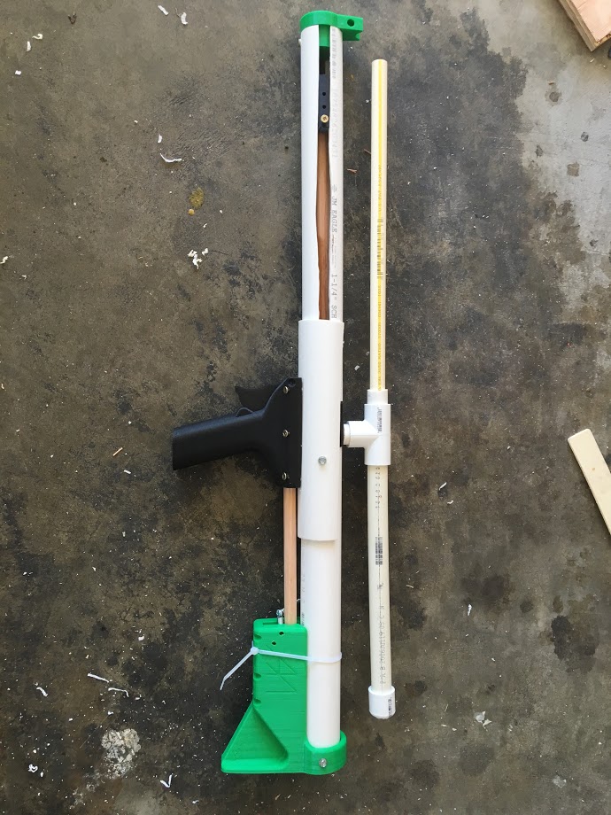
Works ok, considering I kludged most of the parts. I used an oring instead of a skirt seal with my plunger head, a rubber grommet I found instead of a seal in the pusher-redirect, oak dowels instead of nylon (though that is probably less of a kludge, they seem to be doing their part just fine), an RSCB instead of a Y, and the list probably goes on. Unfortuneatly, the RSCB doesn't attach the way the Y does so the front support I griped about doesn't fit. Womp-womp.


My really sketchy range test puts an elite sucker dart out of that RSCB at around 21 paces. A triad fired the same way with the same dart went 16 paces.


Notes/Comments:

  • The built is *super* easy to put together, once you have the parts in front of you. The parts are not all easy to acquire though, ideally you'd need a McMaster order, a 3d printer/order, and a trip to the hardware store for 1-1/4" PVC, 1-1/2" PVC, 1-1/2" 200 PSI PVC, and 1/2" CPVC (even if you're using something else for the barrels, you need a stub to plug into the blaster). Most of the machining is easy, but requires some attention.
  • The trigger is tricky and finicky. Partly this is due to my changes, but partly due to the blaster's design:
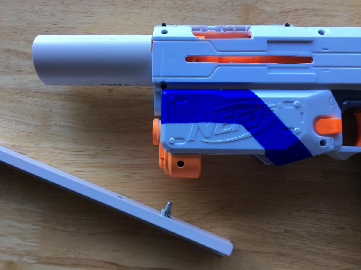
    • You need a slot cut in the 1-1/4" PVC to accommodate the sear, but because it's in a solid printed part, the position it needs to be in is really hard to judge. A cutting template would help, but you'd also have to take care to drill the stock/trigger holder part into place after cutting so you know for sure the sear fits correctly. I'm pretty sure I used a 1/2" drill bit to make the slot that the sear rides in and cleaned up the holes by tipping the drill, and then followed up with a knife.
    • The part *I* may have caused is the pull - it is stiff. But again, I'm using my own plunger head that uses an oring instead of Aeromech's that uses some kind of fancy seal.
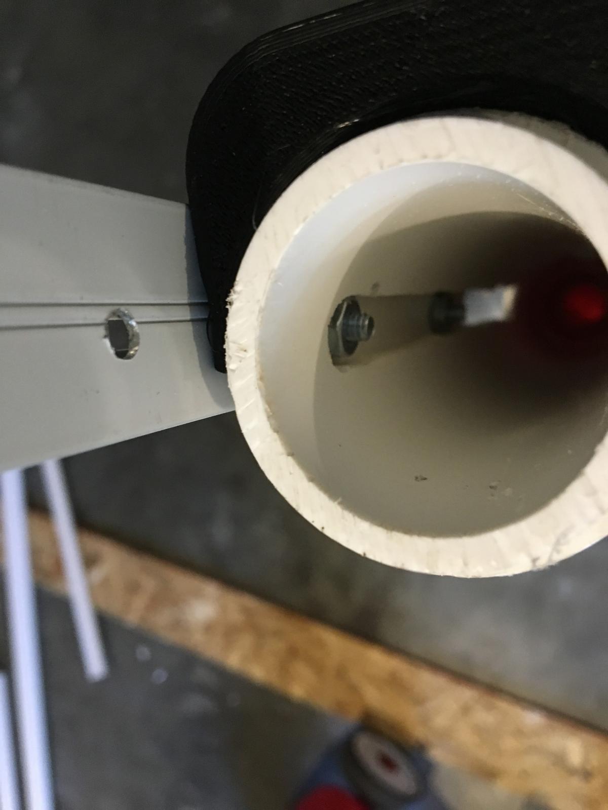
    • Another finicky bit - the connection between the trigger and the plunger is difficult to work out, again because the trigger sear is completely encased in a printed part that needs to stay firmly attached to the PT. I suppose using a clear PT would help with this, but deciding how much length to put on the trigger rod took experimentation, and then figuring out where to attach the trigger took more experimentation. My version does not have the trigger stopped in any way from just falling out of the blaster, which is fine for my experimental use, but not ideal for a production/war ready blaster.
  • The stock terrifies me slightly. It shouldn't just explode, but there is a lot of force being put onto that printed piece. Putting a PVC spring-retention ring in wouldn't be hard and would probably make the stock qualms less relevant.
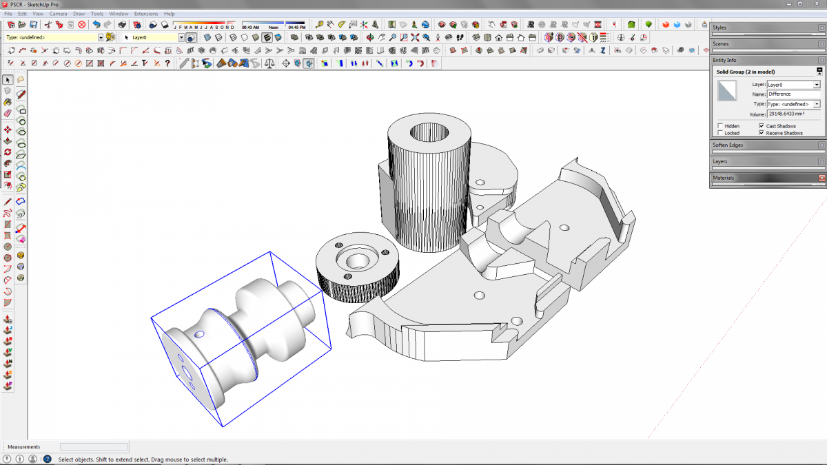
  • The grip feels awesome and solid (I didn't print it solid, it just feels solid - I think I used 1.6mm walls w/20% infil and printed with support. The end touching the grip-clamp was down), but the attachment was a bear. I'm not actually sure how Aeromech did it, but I drilled out the holes that are on the inside and screwed it on from outside. Remodeling that for better/easier attachment would be preferable.
  • Aligning the grip and the stock is very important and shouldn't be rushed, I may have a sticky trigger because mine doesn't align perfectly.
  • Many of the printed parts suffer from a similar, difficult to avoid, problem: You've got holes pre-drilled in them, and you really need to use those holes (and only those!) because the printer put extra material there. But you can't *see* those holes when you're driving your screws, so you need to figure out a way to transpose the marks from a printed piece to a non-printed piece. I didn't do it for the front grip (not shown, pressure is enough to move the PH-pusher forward, a screw sticking out does the rest), did it for the support (but then had to take it off anyway to put the front grip on and it wasn't doing anything), and drilled out the grip so I could attach it from the outside. Short of more printed pieces, I'm not sure how you'd get around the issue elegantly. Templates are a possible inelegant solution.

All-in-all, it's a cool blaster and you should build one if you've got a printer and can get the right parts. It isn't as plug-and-play as it looks, but the machining time is pretty trivial once you figure out a way to get it done. If you don't have a printer, wait for Slug's version, which looks like it'll trade printer time for your time, but then be easier to assemble when you're done cutting it out.


  • 1


#354874 2 Home-Built Retaliator Ergonomic Mods

Posted by Meaker VI on 08 July 2016 - 02:50 PM

So, since it's time for post #500 and I've been talking it up for awhile, I'm posting my Ergonomic Retailiator mods. Basically, a pump-action setup and a collapsible stock. Both of my builds use 3d printed parts, neigher require 3d printed parts when used on a Retaliator or other springer. I fully admit stealing the base 3d models I used to make this from Thingiverse and the Rainbow Clan, links to their parts are at the bottom of the page. I extensively modified all the parts, though the ESLT plate is the only one that didn't really require it.

Final product:

IMG_1470.jpg
 
The whole project took an hour or so once I started working in earnest. Knowing how it's supposed to go now, it'd probably take less.
 
FYI: Priming is a tad rough. This is because there is a bump in the body of the blaster. I think doubling up on the priming bar might help, or putting it outside the stock slide but drilling through the slide to engage the bolt directly, or adding a piece of something to ramp it more gradually, or grinding down the blaster body. I'm not sure I care enough to take the time to do those things right now.
 
Tools used:

  • Drill
  • Drillpress w/ 3/8" router bit (slot cutting; if you do it differently you might not need to cut slots. You can obviously cut slots however you please also - hand saw, dremel, piece of mason's line threaded through 1/16" holes drilled at the corners of the slot and used as a saw, whatever)
  • Screwdriver (#1 phillips for the shell work, whatever you need for the screws/bolts you picked for the new stuff)
  • Saw (I used Japanese-style pull saw. You can use basically any saw, or a PVC cutter, or a pipe cutter, or mason's line again, or whatever else you cut PVC with. No shell cutting req'd)
  • 1/8", 3/16", and 1/4" drill bits.

Materials used:
 
Stock:

  • (CTF) 1-1/4" Sch. 40 PVC Pipe (+/- 6", cut-to-fit)
  • (CTF) 1" 200 PSI  PVC Pipe (Thinwall - it's used for yard drains while Sch. 40 is used for household plumbing drains, so look/ask in the yard drainage department of your large home improvement store. I got mine at Lowes). Thinwall is important for fitting over the plunger tube buffer that sticks out of the back of the blaster. (Again, Cut-to-fit).
  • (1) If you're using the stock for any blaster, use thinwall and this 3d printed adapter:Attached File  Stock_Combined.stl   169.42KB   346 downloads. If you're just using it for the retaliator (and other blasters with the buffer tube) you can probably just attach the thinwall direct to that, maybe with some e- or packing-tape to stabilize it. The way it's built won't allow it to be readily removed on any blaster.
  • (1) If you want it, the 3d printed butt-plate from the above link. Otherwise, a 1-1/4" T works in a pinch, or whatever you want to hobb to gether (1-1/4" PVC endcap or plug secured to a plate)
  • (1) I haven't done this yet, but a plate to make the buttplate stronger. I'm planning to use plywood or a chunk of 2x4.
  • (5) #8 x 1/2" screws. I use hex-head, you can use whatever drive style you want.
  • (1) And lastly, and most importantly: A 1/4" X 1-3/4" Long cotterless hitch pin (Lowes H#881123).

Pump-Grip:

  • (CTF) 1-1/4" Sch. 40 PVC (+/- 12", Cut-to-fit)
  • (CTF) 1-1/2" 200 PSI PVC (Thinwall, see note above)(+/- 4", Cut-to-fit)
  • (2-3) #8 x 1/2-3/4" bolts & appropriate nuts (depends on your priming bar, mine is pretty thick. If nessecary, go long and cut to length later)
  • (1) M5x16 bolt, washer, and nut. (Again, my priming bar is thicker so you may need to cut the bolt or use another nut or two to get the spacing right.)

2017 UPDATE: User Rook1872 on Reddit was asking for ideas while doing this project himself and discovered that a socket-head #6 can sort-of press fit into the sled as well. Hereare his pictures. He said keeping the blaster's slide helps structurally to prevent rocking and with the look; I agree and might have done it at some point with my solution here.

  • (CTF) Something to use as a priming bar. I'm using scrap aluminum from a screen door that approximates a U-chanel. I suspect a wooden yard stick or several paint stirrers glued (With wood glue! Nothing else!) together would work as a minimum, but I haven't tried it. They're usually free or nearly so, so I won't feel bad if you do and it doesn't work.
  • Optionally, some kind of glue to stiffen it up.
  • Optionally, This part for the grip: Attached File  Grip.stl   294.42KB   355 downloads. Or just use grip tape. Or nothing.

Pretty sure that was it. It's an easy mod.
 
DISCLAIMER: I accept no responsibility for you being bad at building. Use caution with power tools, don't get hurt. I am not implying any kind of guarantee about the correctness of this information. Read all instructions prior to building. Build at your own risk.
Stock Instructions:
 
This is a model showing what you're building:
Stock.jpg
 
Steps:
 
If you're printing parts, get those together.
 
IMG_1447.jpg
 
Once that's done, cut your 1" PVC and 1-1/4" PVC to length. You want about 2" of overlap between them. I did this by holding the pipes in their places while holding the blaster in the firing position and just guessing at what length would be good for me. I suspect 6-8" is a good starting place. Cut the 1" first, then the 1-1/4" as you can slide it on the 1" and see what length will work best on the blaster. If you've got the material, cut long (12"+) and then shorten it later.
 
Secure the 1" PVC to the blaster with a #8x 1/2" screw. Drill a pilot hole through the PVC and into the shell. You don't need to drive it all the way in if you're not using the printed part, just enough to keep it in place. You don't want it to mess with the plunger rod. If you're using the adapter, sink it but not too tightly as you don't want to split the printed part.
 
Secure the 1-1/4" to the butt-plate or T or whatever you're using.
 
Put them together and check the fit on your body in the positions you want (I just did 2 - open and closed).
 
Using a 1/4" bit, drill all the way through the assembled collapsed pipe stock. You want to only drill one hole in the 1" pipe, about 1" from the open end of the pipe - with it apart mark where that is on the 1-1/4" by holding it next to the 1". Do it in one push all the way through - this is how the hitch pin will travel. This is easier with a press, center punched holes, a V-block, and predrilling. I did it by hand. Check that your hitch pin fits all the way through and locks in. See picture
 
IMG_1456.jpg
 
Remove the 1-1/4" rear stock piece and drill a second hole at your extended point all the way through again. This needs to be 1-2" inside the open end of this pipe. The tricky part here is that it needs to line up exactly with the other holes. It's not pictured, but I missed and had to widen the hole on the back of the pipe when I did mine. I did it entirely with a hand drill, so you should be able to as well, but a press set up with a proper jig would make this more reliable.
 
Put the 1-1/4" back on, slap the pin in, and you're done. It's not super quick to change, but you could easily do it in the field while in cover.
 
IMG_1457.jpg
 
Pump Instructions:
 
Here's a model of the grip I used:
Grip.jpg
 
Steps:
 
Pop the blaster open, then remove one (or both) of the screws holding the slide action and remove it. You don't need it except cosmetically. I kept half on and will probably cut it short and put it back.
 
Cut your 1-1/2" PVC to length to use as your pump-grip. This should be +/-4", or the width of your hand, or the length of your printed grip.
 
Cut your 1-1/4" PVC to length. This is done by A) sliding it over the barrel stub, which the PVC conveniently fits right on (Mine might be magic, so you may need to ream it a bit or make a relief cut in the PVC so it can flex wider) and B ) Marking a point an arbitrary distance forward of the face of the blaster that lines up with the blaster in the primed position - check it with your grip in the primed and unprimed positions before cutting.
 
Get your priming bar and check that it's long enough to go from the bolt to the pump grip in both open and closed positions. Then drill a 3/16" hole in one end for your M5 bolt. Drive the bolt in and put the washer and nut on the oppisite site as shown.
IMG_1443.jpg
 
This bolt (and only this!) fits into the slide:
IMG_1472.jpg
 
I suspect that others would work, but this was the first I found that fit so I'm sticking with it. Any good hardware store should have them, so it shouldn't be that hard to find.
 
Drill out your holes for the rest of the bolts in the pump-grip and line them up with the 1-1/4" PVC and the priming bar. I had, again, done it by hand and poorly, so mine is all askew. Next time I'll try to be better, I promise. Drill the further hole at the end of the slide action through the 1-1/4" too so you know how long to make the slot.
 
IMG_1473.jpg
 
Make the slot between those holes. I needed it to be 3/8" to fit both my router bit and, as a happy coincidence, my bolt size.
 
Get those bolts through the assembly and tighten as much as you can.
 
On the 3d printed part - It isn't optimally designed for the position of the priming bar, so I drilled through it in addition to the grip. If you want to modify the print, stretch it so the grip part is further from the pipe.
 
Once it's assembled, you're all done!
 
IMG_1471.jpg
 
You also might note that I didn't ever actually attach the 1-1/4" to the barrel stub. You probably should do that, but I didn't because the bolt sled should stop the pump grip from hitting the 1-1/4", and I can't see how else it'd come off normally. If you had to modify the 1-1/4" to get it to fit or if your fit is looser than mine, you should attach it somehow. As long as you use screws or only glue to the barrel stub, it should still be possible to disassemble the blaster.
 
Links to original parts I used to design the parts included here:
 
Grip I hijacked

Stock adapter I hijacked

ESLT; I just hijacked the Butt-plate


  • 1


#354719 Plusbow Rev. 3

Posted by Meaker VI on 30 June 2016 - 04:19 PM

Do you even need the endcap? Wouldn't sandwich plates work just as well? Side-drilling these thin sheets is always a bear.


  • 1


#354461 Air cylinder for pushing darts through clips.

Posted by Meaker VI on 22 June 2016 - 09:59 AM

I kind of dumped the ARR project upon the realization that it would an awkward marriage of a springer and an air-powered blaster.

 
I think the Austrailians fairly regularly do semi-auto air blasters, dumping the spring action as well. Boltsniper's BS-12 is one of the only spring/air blasters I know of, and it sounds like you need significant air supply to run it in air mode.
 
Slug, are you back for good or just temporarily?
 
Also, I totally forgot about this thread but since got my own 3d printer and made up a magwell that might fit in this project:

IMG_1176.JPG


That's 3/8" PEX feeding a suction head elite dart from a mag into some kind of PETG. The foamed appearance is because my nozzle clogged up partway through the print - I'll need to redo it, but am waiting until after I've redesigned the lock. I'm waiting to do that until after I do some testing with it to see if it'll do what I want it to (note that it's got 1/8" holes running all the way through that you can't see here).For now, it seems to feed well and my printer's tolerances are tight enough that the lock not working correctly isn't a huge deal.


For printing, the mag should point up on your printbed. if you open the file there will be disposable supports that I've added in that are 0.01" or something away from the body and should keep the round top of the magwell in place. This whole thing is supposed to nest into 1-1/4" PVC, but some shaving may be required depending on your PVC's ID.

Attached Files


  • 1


#354188 Lack of NIC Nerf wars this year in Washington?

Posted by Meaker VI on 14 June 2016 - 02:22 PM

While researching this a bit, I just saw a nerf-gym is located in Des Moines (who plays there, however, I have no idea), and a few large-scale highschool 'Nerf Wars' played in the bad old fashion highschoolers are want to use (driving around with blasters and shenanigans). You'd obviously need to be a highschooler at said school for that to work though.


Really, I recommend starting up your own group. Post here and reddit so those in/around WA can see it, invite your friends, etc. etc. for a nice day in the park. If you've got the time free, just do it every weekend same time-same place or something. Who knows? Maybe then you'll get a community built where you are, and not hours away through grueling traffic.


  • 1


#353291 RSCB clip + Bullpup + Nerf blaster shell?

Posted by Meaker VI on 06 May 2016 - 10:18 AM

I think at first, you should just build a snap carbine. They're cool, and you can probably make it a bulpup by putting a trigger up further and a rod pushing the snap trigger, but do you really want to have the rod accelerating so close to your face?

I think DIY blasters are fine out of shell, but if you find a blaster that houses 1-1/4 PVC plunger tubes, than it's fine. 


I wouldn't even do that. Do a pump snap or pump bow; those carbines seem like more work for no added benefit. Then drop it in a shell or not.


  • 1


#353106 PCSR: A new homemade design

Posted by Meaker VI on 27 April 2016 - 05:49 PM

Ok meaker wasn't sure if you released it or anything. That's why I put no offense just in case it was just for yourself.

 
This is an aside and a bit of a pet peeve of mine that I'm reading between the lines of your post, so if you'll bear with me:
 

Spoiler


  • 2


#353085 PCSR: A new homemade design

Posted by Meaker VI on 27 April 2016 - 10:01 AM

Intentional necro to alert those interested of relevant information. Files are up. Instructions/complete parts list will be made available as the night rolls on


Linky linky --> https://drive.google...WG8tOGxPNHJ4WnM


*Just* when I had started to make good on my threat to model my own version:

PSCR.png


Oh well, now I've got those to compare with yours.


ED: Oh right, printer settings. I've actually switched from Matter Control to Cura because I wasn't getting results in Matter Control and I was in Cura (probably more due to my bed adhesion troubles than anything, so I maybe should switch back since MC is better in many ways). Anyway, the benefit of Cura is that it lets you specify thicknesses instead of perimeters. I figure for our work we should be using 2.0mm-3.0mm, keeping in mind nozzle size probably wants to be a multiple of whatever you use (i.e.: 5 perimeters with a 0.5mm nozzle is probably 2.5mm wall thickness). I've also found that this thickness results in some parts (Large ESLT parts especially) ending up solid because the perimeters overlap and there is no infill. When I messed with it, for many of these kinds of parts, there seemed to be a mostly insignificant difference in both time and material use between doing 100% infill and 20-30%.


I'm using blue painter's tape with rubbing alcohol on PLA, but that's because I was having such a hard time getting ABS to work that I wanted to print something and not have it end up a messy rats nest. The tape/alcohol holds tenaciously, especially since I've also been using a raft (probably need to adjust the bed again, these kinds of parts have/should print without one but when I tried the other day I needed the raft). I may go back to working on getting ABS running if these PLA parts don't hold up. I've read that the painters tape/alcohol works for that as well.


My machine is a Wanhao Duplicator i3 v2.0, their offering as of this post is the v2.1, for the price I can't say enough good about the machine. It's $400 shipped, has an ~8x8x8" build volume, heated bed, and takes no more than 30 minutes to assemble. Assembly is something like "unbox machine, attach 6 clips and 4 bolts, then level print bed." I'm not sure it's a very experimental machine; you may not be able to print higher-temp exotic materials or whatever, but I've printed both PLA and ABS with some measure of success and really that's all you'd need. For an enclosure, I use a clear rubbermaid/sterilite/whatever bin that fits over the whole machine and cost ~$12. I got a glass build plate and some kind of silicone heat transfer pad from amazon to attach the glass to the bed for another $20 or so. The machine came with some kind of pad attached directly to the heated bed that was *super* adhesive, but so super that I had to chisel parts off (!), so I removed it.


  • 1


#352521 Looking for the ideal Nerf rifle

Posted by Meaker VI on 30 March 2016 - 10:15 AM

The reason I don't want to use pellet rifles or airsoft, is 1) They could damage my interior without a well set up backstop.  2) The ammunition is small, and I don't want to have stray pellets/bbs hidden about the living room.   3) Airsoft/pellet rifles require a decent amount of cleaning/maintenance, and are more expensive in general.


FYI: The first airsoft pistol I picked up came with a the pistol, a backstop, pellets, could reliably hit targets further out than any NERF blaster, and was about $20. A cheap spring pistol is perfect for indoor plinking, and all it takes to stop the bb is a loosely draped sheet or towel. I never once needed to clean the pistol in years of using it. If plinking accuracy is your goal, a spring airsoft gun is probably your best bet.
 

I'm still very interested in better designs and home builds, which would be amazing.

 
See if you can get a BoomCo Halo Magnum or Farshoot; those can have crazy range (basically just a double spring mod and maybe plug some holes) and have much better accuracy than NERF blasters because they've got better darts. If you like that, pick up a flipbow or breakflip for a more rifle-sized spring blaster.


Failing that, the Mark-8 is an entry-level homemade, but there are loads of other good plans if you've got the tooling and skill. Basically, any homemade will produce more power than any production blaster, which should equate to more range/accuracy. The biggest thing homemades have going for them is actual barrels. No production blaster has a barrel that does anything more to guide the darts than your Jolt does. All those fancy barrel extensions are shrouds that rob power, range, and accuracy from your shots.


I would recommend the Buzz Bee Sentinel (here)


Second the sentinel, very good reviews on power OOTB. It sounds like it may be the exception to my above statements.
 

Edit: Someone hacked my account! I didn't say "loser rifle", I said "s n i p e r rifle". I didn't say "eat shit"!! The original said "s n i p e". I swear I that was not in the original post.
Edit Two: For some reason, when you type s n i p e r it automatically changes it to loser rife. When you write "s n i p e", it turns to eat shit.


I thought this was common NH knowledge. Sniper gets translated to looser, and there are (or were) several other filters, one of which you've stumbled on. Most were kind of in-jokes, but the sniper one was because no NERF blaster can function as a loser rifle. All the darts will be accurate to about the same range, regardless of blaster, and that range is less than 100'. Accurate shots are probably maxed out at 20-50', where it'd be just as easy for me to throw something at you.


  • 1


#352059 Spring into Homemades Writeup Contest

Posted by Meaker VI on 08 March 2016 - 11:05 AM

Am I in good standing? Or did I narf that up with my antics last year?


You must be an active member in good standing (not banned or suspended) during the contest submission period and judging period.


You appear to be neither banned nor suspended, so I'd say yes.
  • 1


#344895 Digital Designs Directory - for 3D printing, laser cutting, CNC, etc.

Posted by Meaker VI on 09 February 2015 - 03:35 PM

This instructable, which I did not write, explains how to get 3d models off of McMaster parts.

That's right, you can get 3d models off of McMaster parts, which you can then 3d print. That's a pretty big deal, at the least you can use them to check the correctness of your part order and you could conceivably use and/or modify the parts to print your design wholesale.


ED: The attached flywheel cage I didn't design (got it from Nerfgeek416 on reddit here), but I did just modify. If I make more changes I'll update here:

Attached File  FlywheelCageRS - Centered - MK1.stl   491.78KB   457 downloads


  • 1