
 Find content
Sup guys,
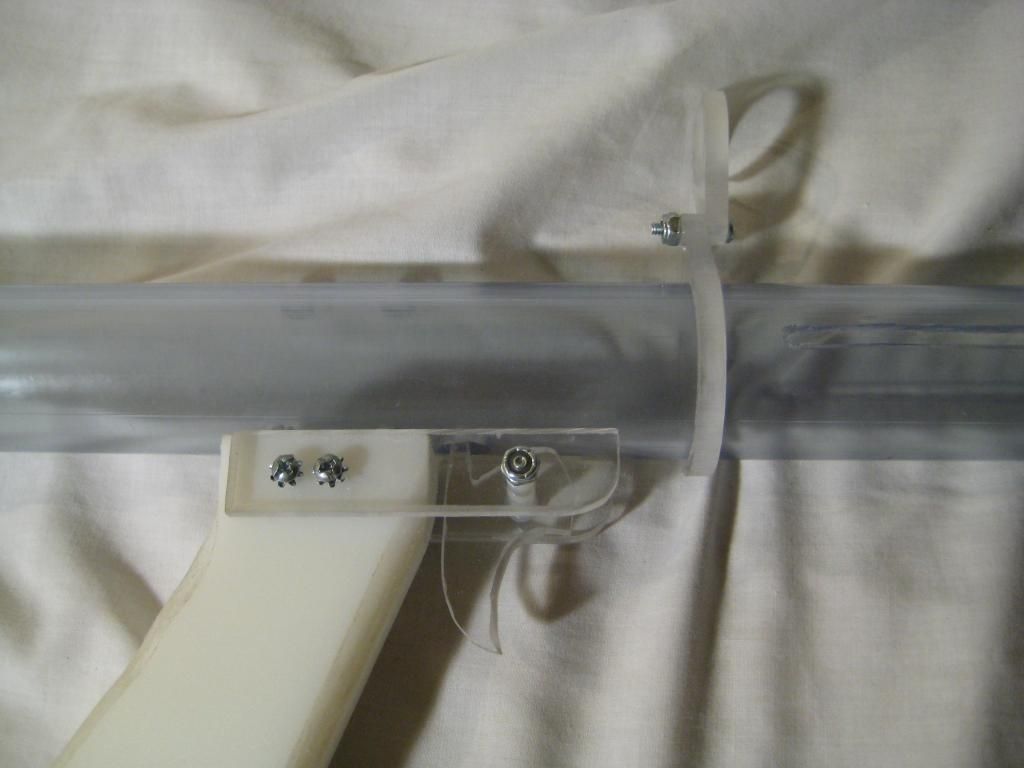
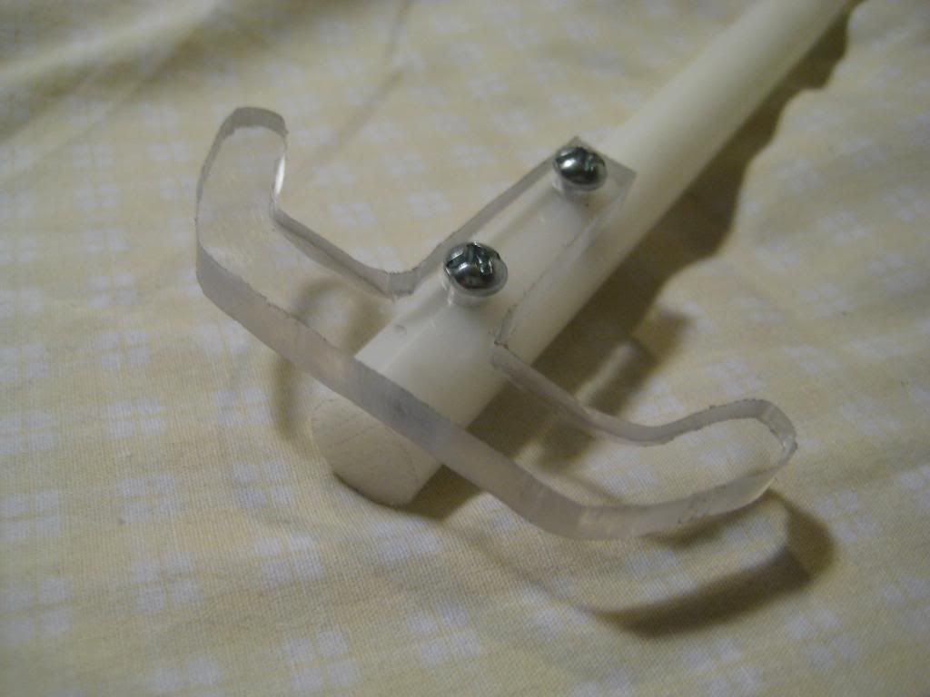
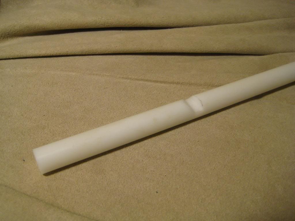
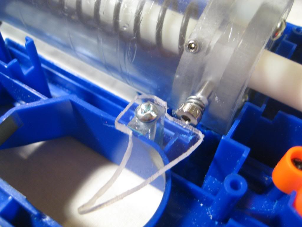
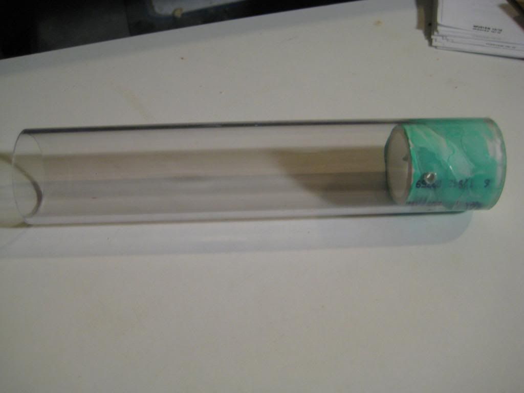
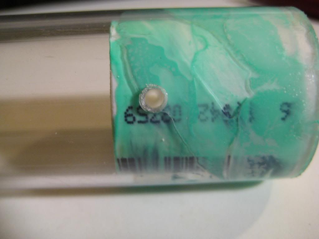
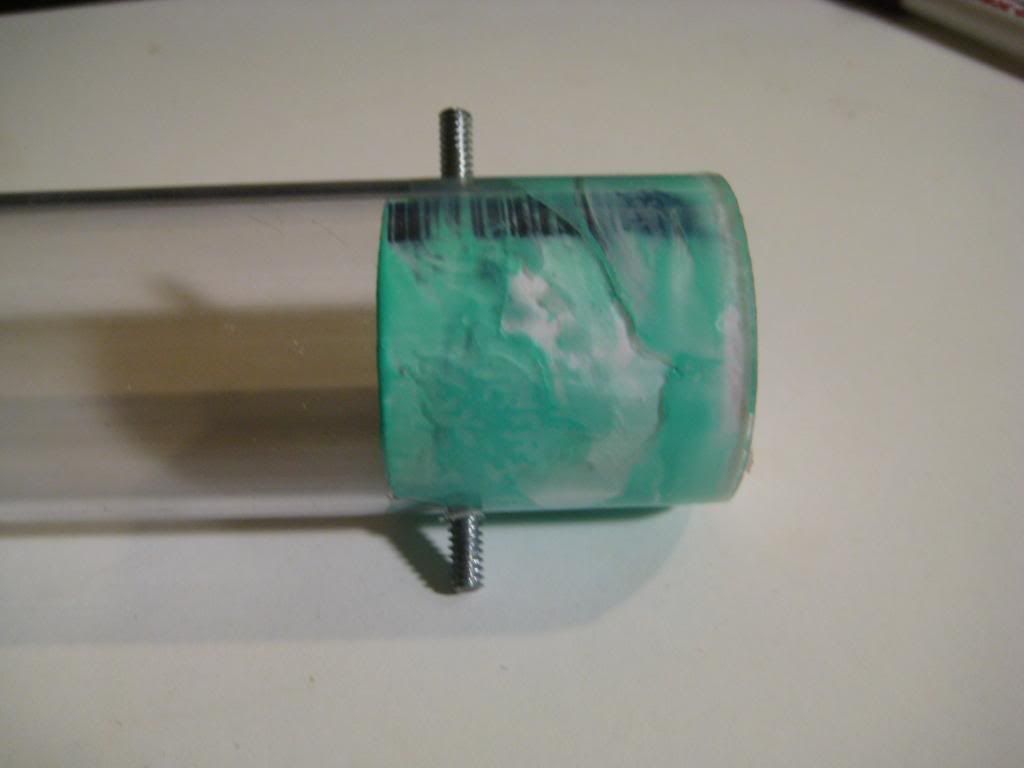
Here's a little something I whipped up to keep the barrel stable on my bullpup. It takes the guesswork out of fabbing your spacer by hand, and it looks pretty nice. I didn't make the big piece quite tall enough, but you get the idea: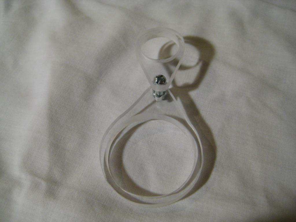
T da B
Member Since 16 Aug 2012Offline Last Active May 12 2015 09:37 PM
Topics I've Started
The Ported Piston plunger head
01 April 2014 - 01:56 AM
Hello lady and gentlemen,
After finally getting around to thoroughly testing this prototype, I'm very excited to present you all with some dope new technology that you may not have seen before! The idea is not mine, but I'm "porting" it over from our sister sport--Airsoft! First of all, let's quickly go over the advantages and disadvantages of regular old O-ring plunger heads:
Advantages:
- Incredibly cheap
- Take up very little real estate
- Easy to maintain
- Long-term reliability
- Low friction
Disadvantages:
- Sealed breeches don't allow air into the plunger (vacuum loading)
- More machining required
- Tight tolerances to get a working plunger head
The Ported Piston, or PP is a modified O-ring plunger head that eliminates the first disadvantage off the list. Here is a picture to illustrate:
Of course, you have to imagine a dart plugging up the right side of each plunger to understand the real benefits!
Writeup:
For this write-up, I'm building a plunger head for 1 1/2'' OD polycarbonate tubing out of 1/2'' HDPE (cutting board). Start by cutting out a disc of HDPE with a diameter about equal to the ID of your tubing. Mark the center and draw 3 lines through the middle (or more if you want more than 6 ports). Try to keep the lines equidistant from each other.
Drill a 1/8'' hole through the center and tighten on a 1 1/2'' 6-32 bolt. Chuck in it in the drill press (if you don't have the luxury of a lathe) and file/Dremel it down until it slides into your tubing nicely:
Now use a rough file and a small square one to get a nice hamburger shape. Make sure the track is wide enough to allow the O-ring to slide up and down a little. Test the fit in your tubing constantly!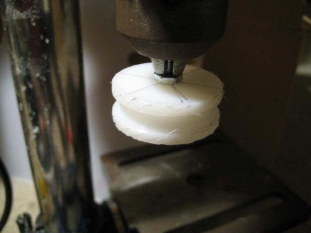
Now mark the holes on top--mine were 1/4'' from the edge. Mark the holes around the perimeter that will meet up with the ports on top--they should be lined up with the O-ring when it is slid downwards all the way: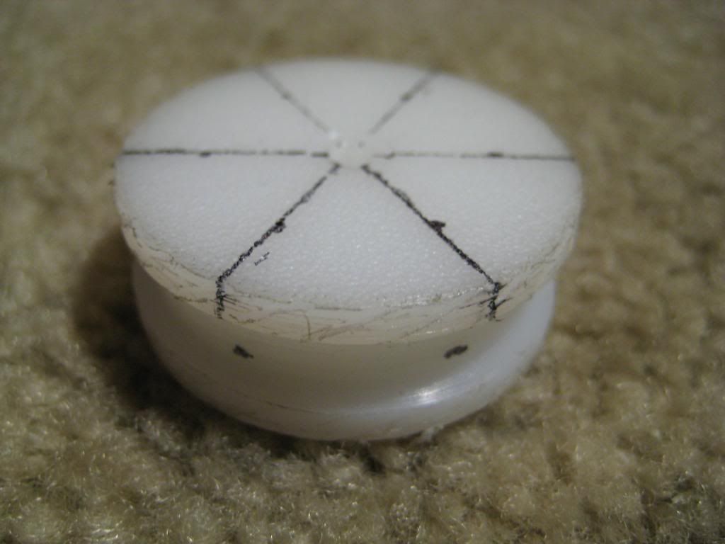
Now drill the holes in the top to a depth of around 11/32'' with a 1/16'' drill bit: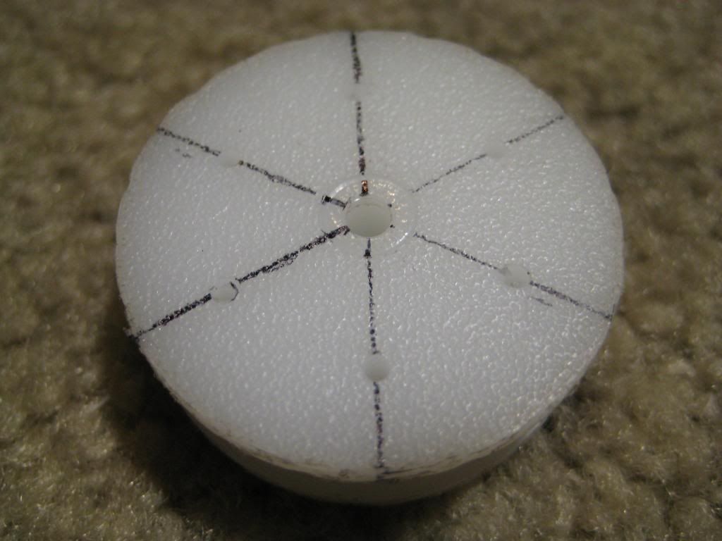
Now drill the holes along the perimeter to meet the previous ones. I centered the disc as best as I could in my small vise and used my drill press. I literally looked in through the upper hole until I saw the drill bit appear at the end of the small tunnel.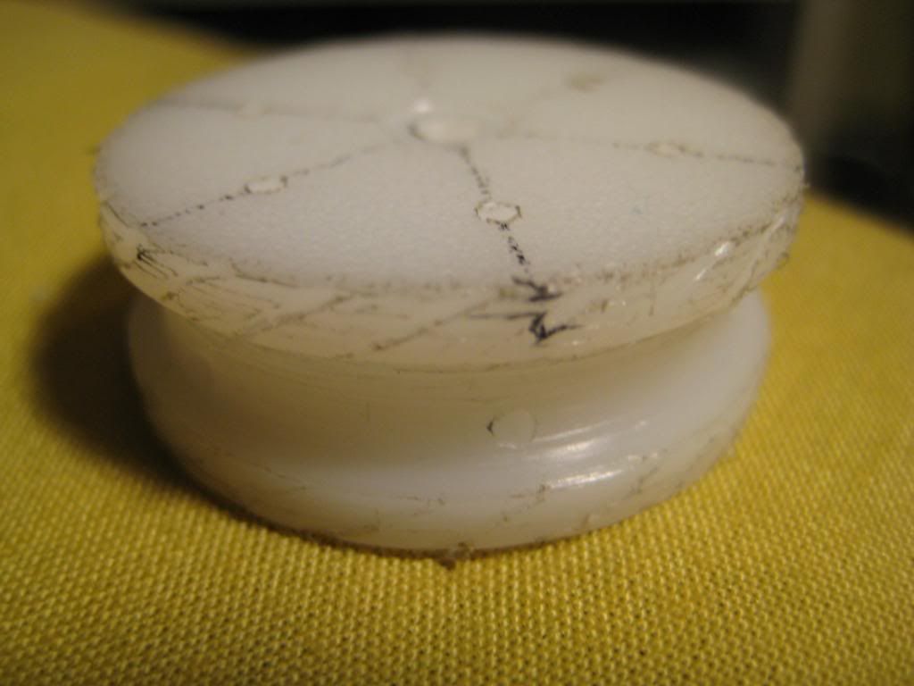
To see if your ports are functioning properly, blow through the hole on top of the disc. Clear out any swarf with a paper clip--it is imperative that the passages be clear of debris!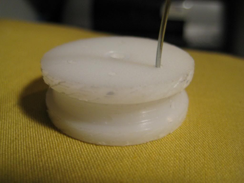
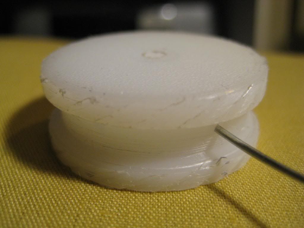
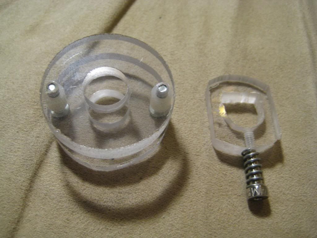
Here you can see what the plunger head looks like when you prime the blaster--the O-ring slides upwards, exposing the ports, then fresh air can flow from behind the plunger up through the ports and into the plunger tube for the next shot. The O-ring is a 1 5/16'' OD O-ring from Ace.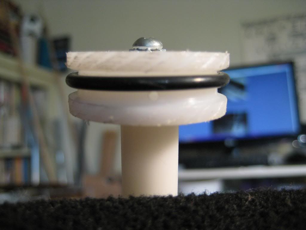
And when you fire, the O-ring slides backwards, covering the ports. As an added bonus, air rushing in through the top ports pushes the O-ring outwards, improving the seal!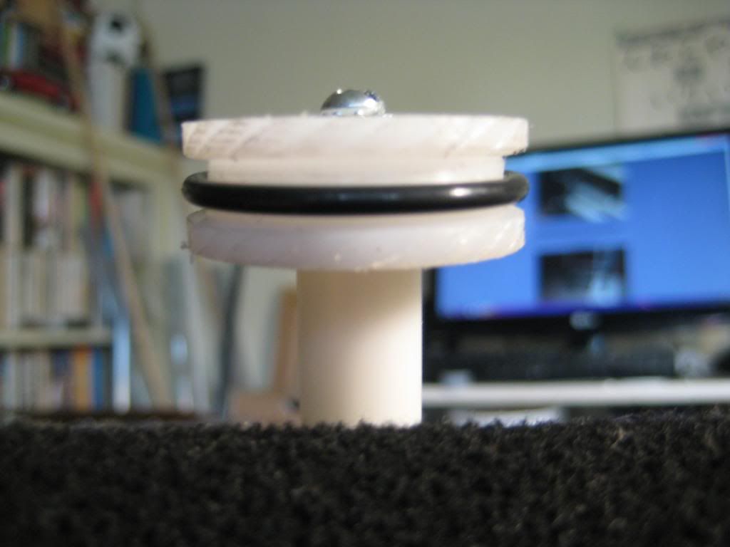
Slapped on a plunger rod: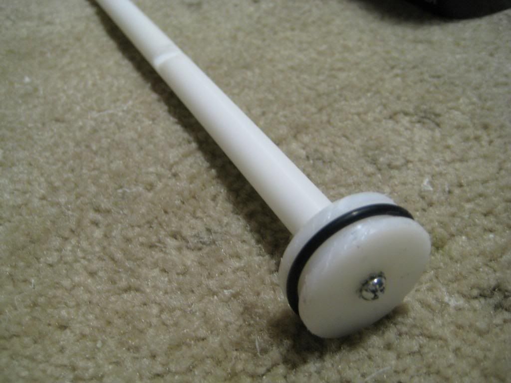
And into my Ported Piston Plusbow (PPP):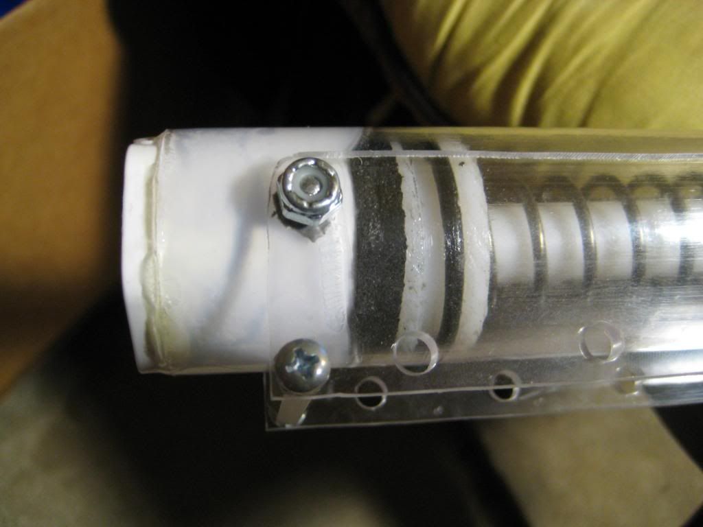
Final Thoughts:
After hundreds of shots worth of testing with various barrels, I'm getting the same performance out of my PPP as my skirt seal RainbowPump! Even with sealed breeches and rapid firing, there is no drop in velocity. Though this plunger head design required a lot of effort, the result is well worth it.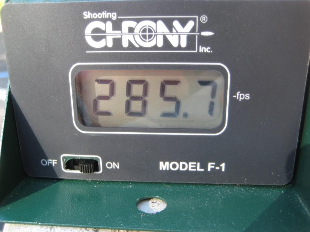
This was the max fps--the average was 260-270. It was achieved with a 12'' slide breech and 1.25'' #6 slugs. I hope you guys found this as awesome and intriguing as I did. No go forth and make yourselves a PP!
~T
Longstrike mod: homemade internals
08 October 2013 - 12:25 AM
Sup NH,
I browse the forums fairly regularly and sometimes I see something that really impresses me. In this case, it was actually a Longstrike! It's not often you get all hot and bothered by a blaster that absolutely blows stock. However, nowadays I see blasters in a different light than I used to. Now that I have the means to create any of my own components, there's no point in reusing Hasbro's internals at all. A blaster's worth to me is now measured in how good it looks and how easy it is to incorporate internals and other goodies. The Longstrike satisfies all my requirements, and just happens to have enough room for a 1.5'' PVC plunger tube! This mod is literally a wolf in sheep's clothing--the shell is the only thing left that's actually stock.
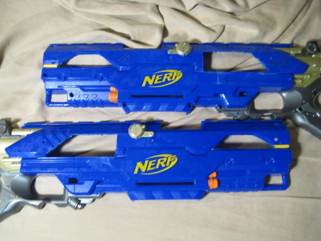
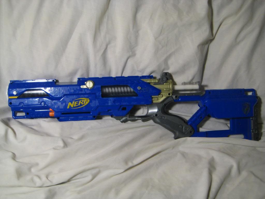
Here's the Longstrike I got for free:
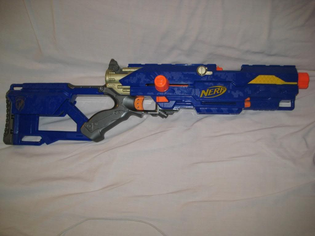
The bolt was stuck, so the owner probably tried to open it up, realized it was solvent welded, and gave up. Sweet!
Required Materials:
Required Tools:
Write-up:
Let me start out by saying that taking apart this blaster can be a huge bitch. There were orange pieces randomly solvent welded into place that actually kept the two halves of the shell from separating. Suffice it to say, I ended up using the Dremel as a samurai sword and severing anything in my path. I think it's a conspiracy by Hasbro to prevent people from modding blasters with too much real estate inside them. Anyways, eventually I cracked the egg. Start by cutting the plunger tube. It should be a whopping 14'' in length:
Now to prepare the front bushing. I secured the bushing in between two fender washers, tightened nuts on both ends, and put it in the drill press.
I used my "ghetto lathing" method to shave down the bushing with a Dremel until it fit nicely into the plunger tube. Use some PVC solvent to permanently attach the bushing with an airtight seal:
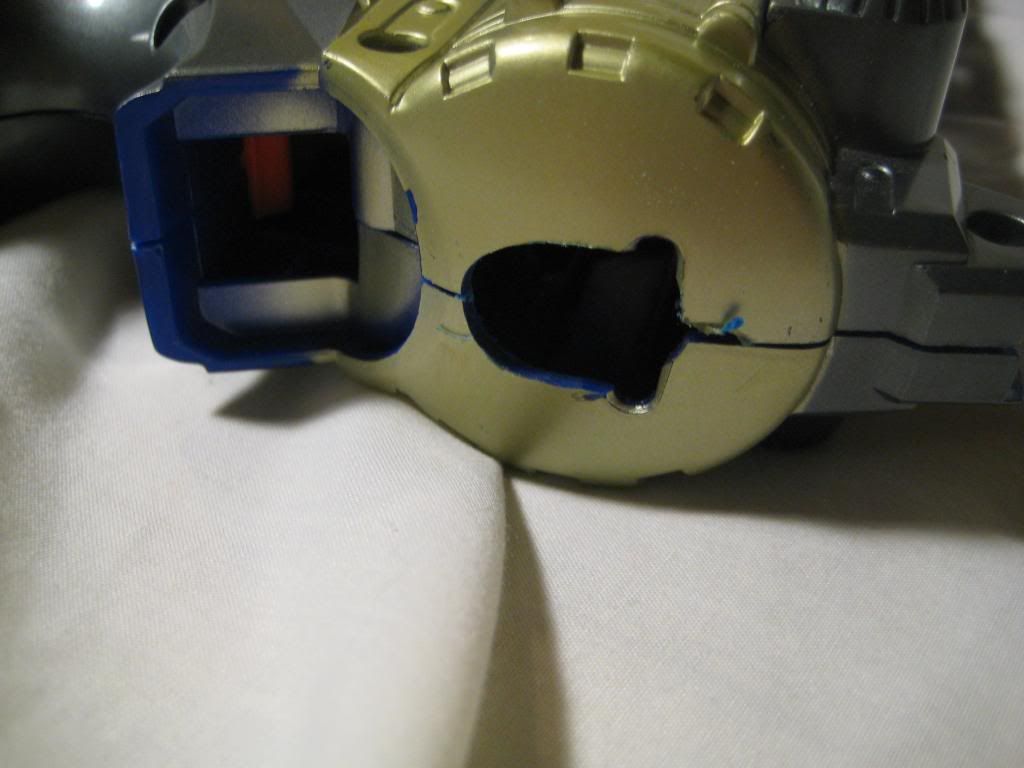
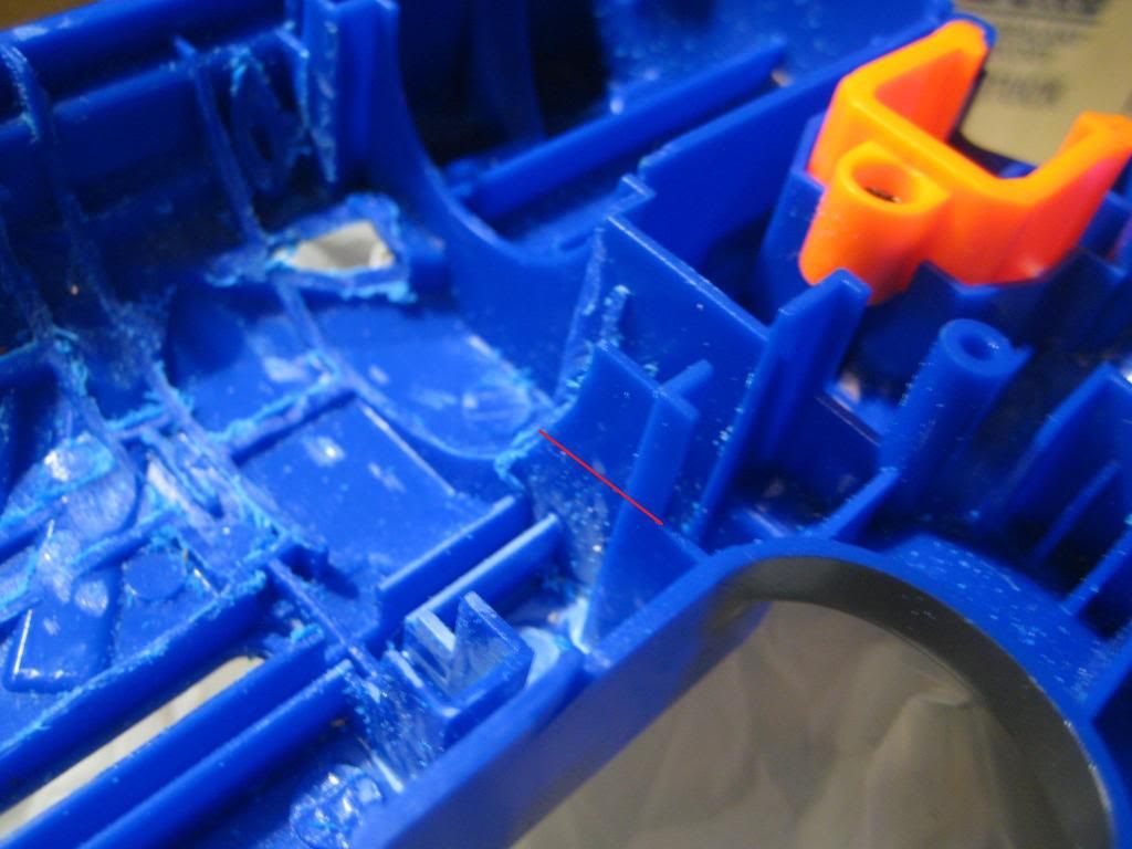
Now for the worst part of the mod--Dremeling the shell to fit the plunger tube. You can make things a little easier by cutting out the gloryholes that I did:
Dremeling the shell proved so frustrating that I even forgot to take a picture of it. Just keep checking the fit with the plunger tube until it fits. The front of the plunger tube should be flush with the front of the shell as well. Anyways, let's finish up the plunger tube. This requires the construction of a Rainbow Catch. I did a write-up on how to make a 1.5'' Rainbow Catch with no templates here.
Stick it in the back of the plunger tube and mark where the shoulder screw will pass through. Drill the hole with the 5/32'' drill bit, then use a small screw to hold the catch in place for more drilling.
Drill four holes with the 7/64'' drill bit through the plunger tube and into the inner ring of the catch. Tap them all.
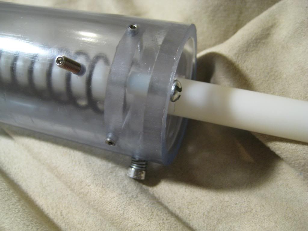
Now that the rear end is prepared for duty, it's time to put the threaded rod through the front bushing. Drill through with the 7/64'' bit, tap, and insert the threaded rod. Drill 9/64'' holes in the shell at the front for the threaded rod. Add glue around the threads to prevent air leakage. Fail to do this and you won't get the perfect seal!
Put the plunger tube in place and enclose it in the shell. Then drill a 7/64'' hole through the shell and plunger tube on either side towards the rear of the blaster. Expand the holes in the shell with the 9/64'' bit. This step is just to insure that the plunger tube has adequate support.
Last order of business is plunger padding. I used a healthy amount of toilet gasket to kill some dead space and insure that the blaster doesn't destroy itself:
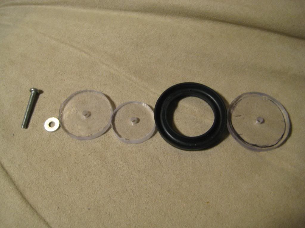
Now on to the plunger rod. Cut a 14'' length of Delrin rod and drill (and tap) one end of it with the usual 7/64'' drill bit.
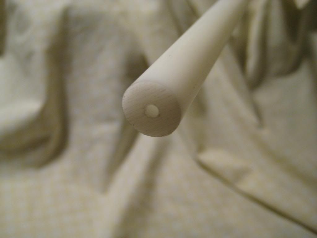
Here is my plunger head. From left to right: 1'' screw, #6 washer, 1/4'' polycarbonate disc, <1/4'' polycarbonate disc, U-cup, 1/4'' polycarbonate disc.
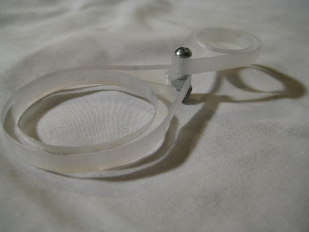
In order to prime the blaster you need to fabricate something here is what I made:
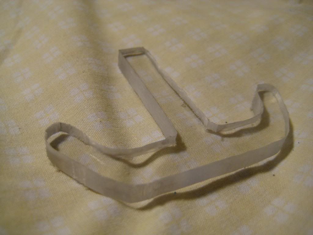
I attached it to the end of the plunger rod with a couple of 3/4'' screws. Later I ended up trimming down the sides, since I was getting some facerape holding my head against the stock while firing.
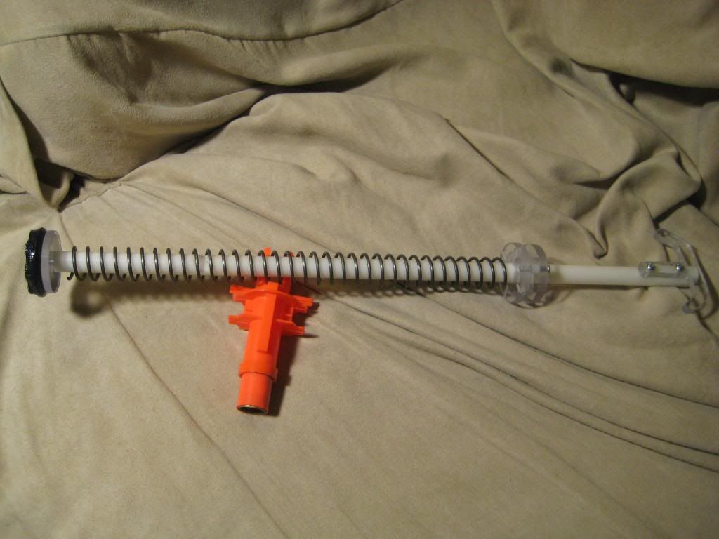
Here is the plunger rod assembled. As you can see, my U-cup was a bit large. Regardless, the seal is perfect. I have discovered recently that 1.5'' OD piston cups plunger heads are the ideal choice for 1.5'' PVC.
Don't forget to Dremel the back of the shell for the new priming rod:
Put the assembly in the blaster and get a friend. Prime the blaster all the way back and get a friend to make a mark right where the rod leaves the shell. The front of the catch notch will be cut 3'' in front of the mark:
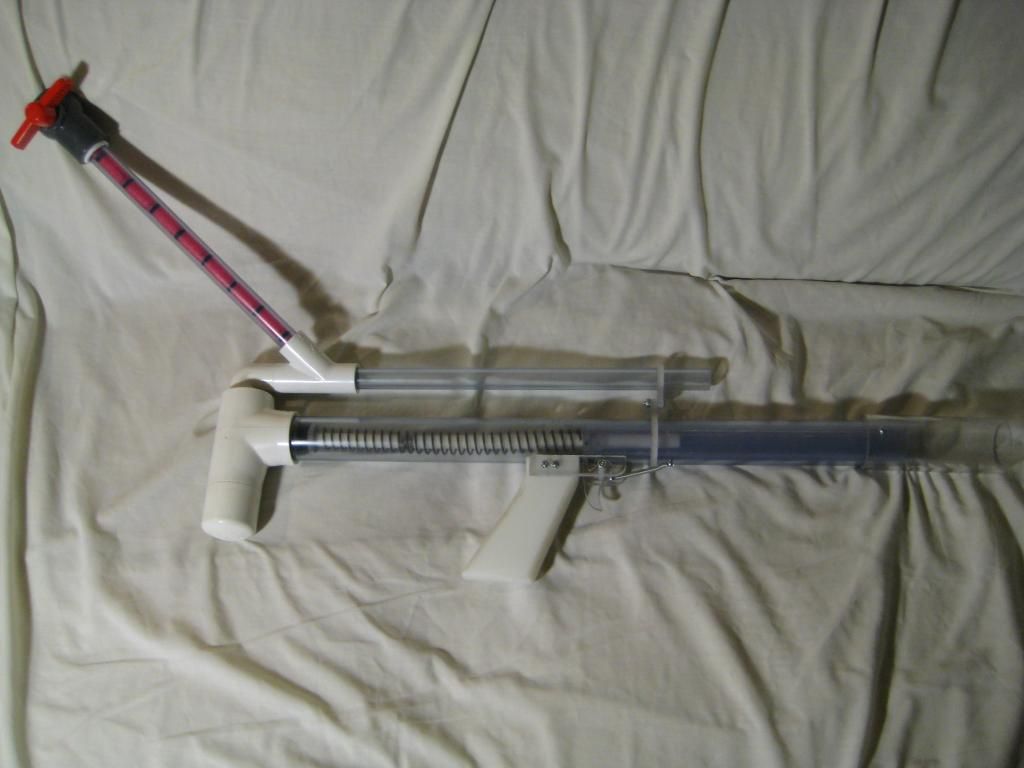
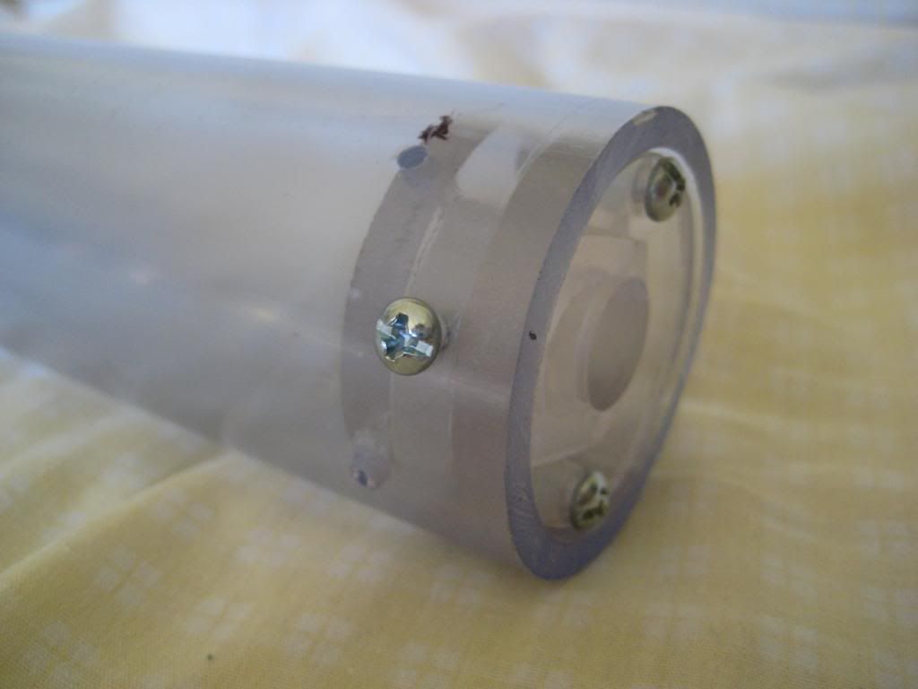
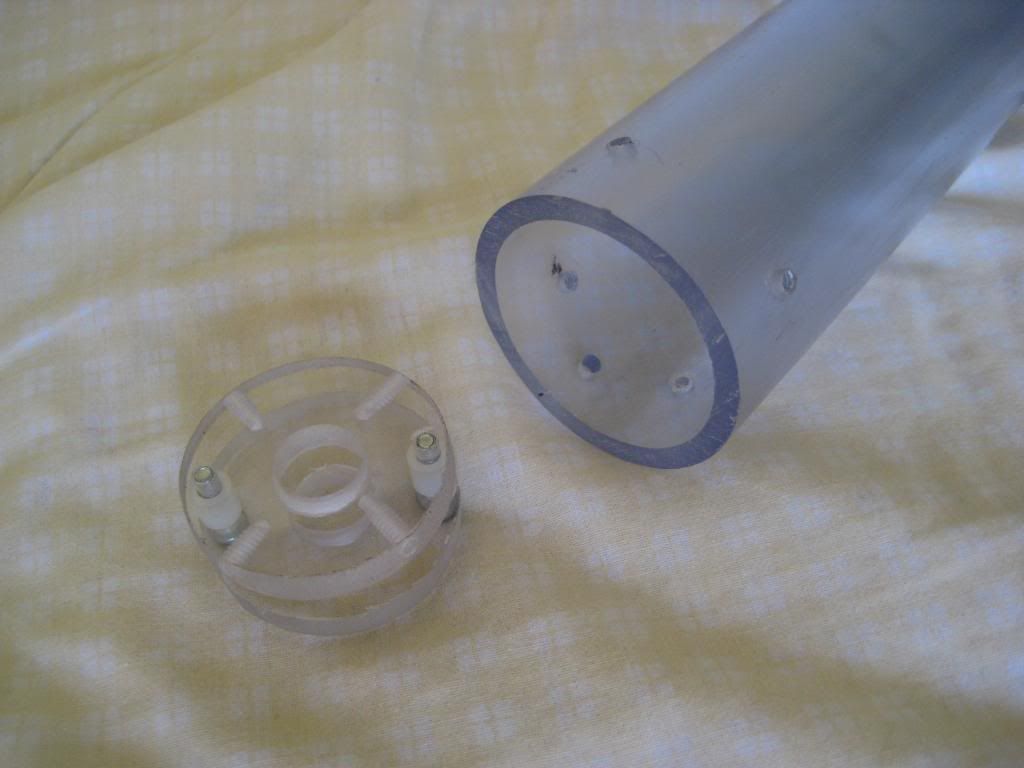
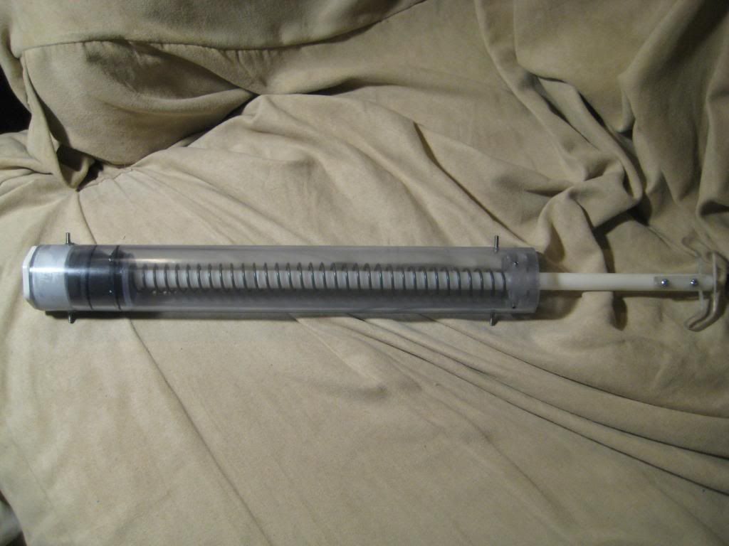
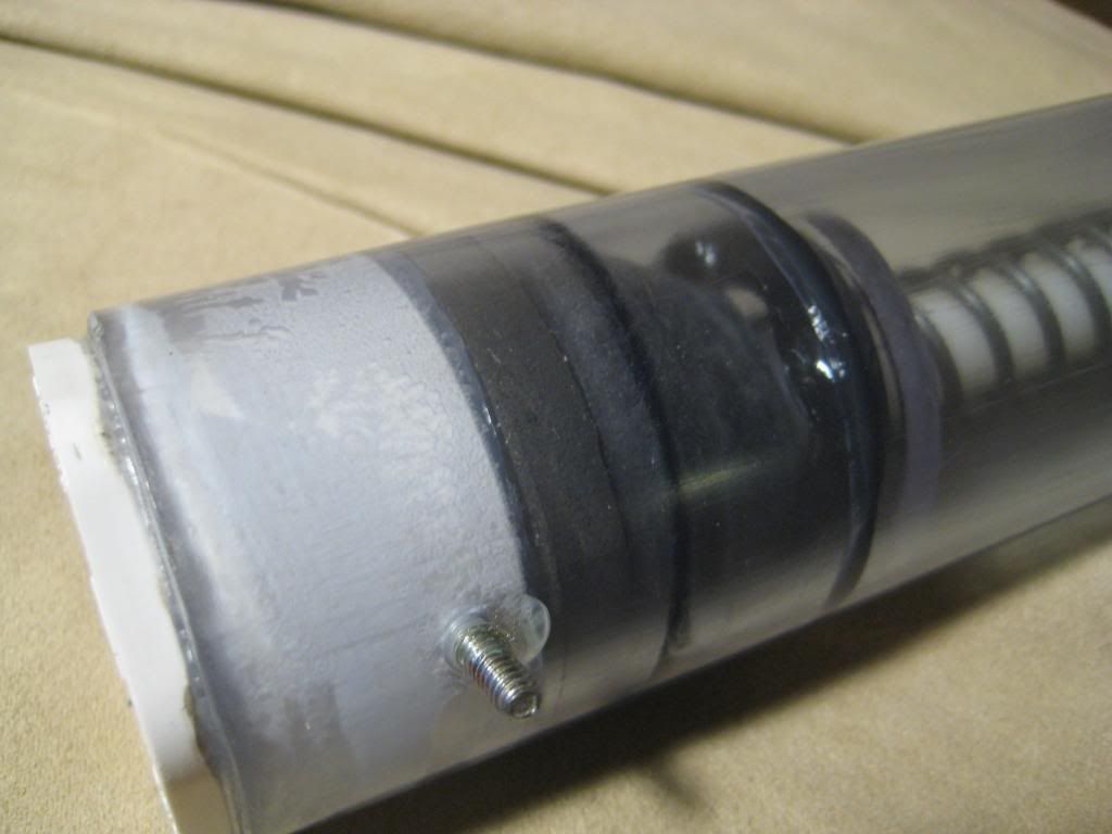
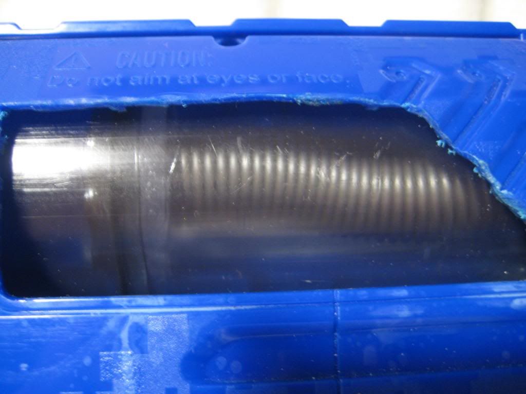
Reassemble everything again, and we're almost through! Here are some shots of the completed plunger tube:
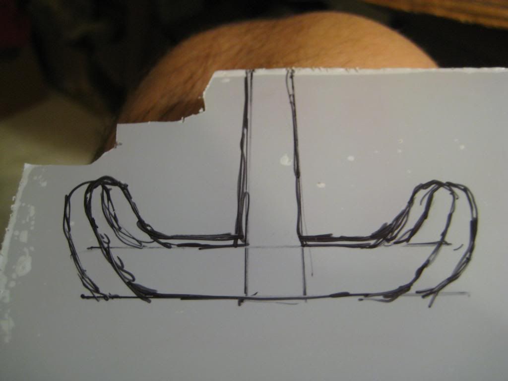
Now for the final challenge--making the trigger! Obi, the original creator of this mod cautioned that this would be the hard part, but I thought about it for a while and arrived at a simple and elegant solution. First, a piece of the shell must be trimmed in order to accommodate the trigger:
Here are some tentative schematics I used for the trigger. The final product was a bit taller and wider:
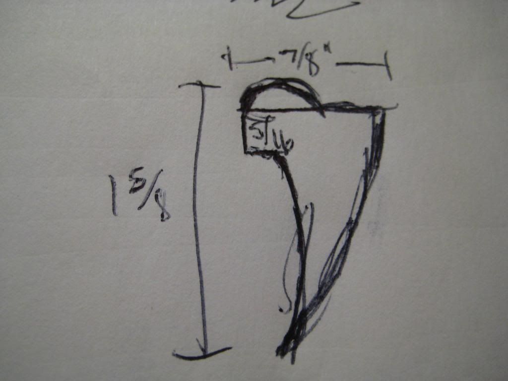
Here is everything needed for the trigger setup. The trigger is 1/8'' polycarbonate, the mount is 1/4'' PC, and the screw is a 3/8'' screw.
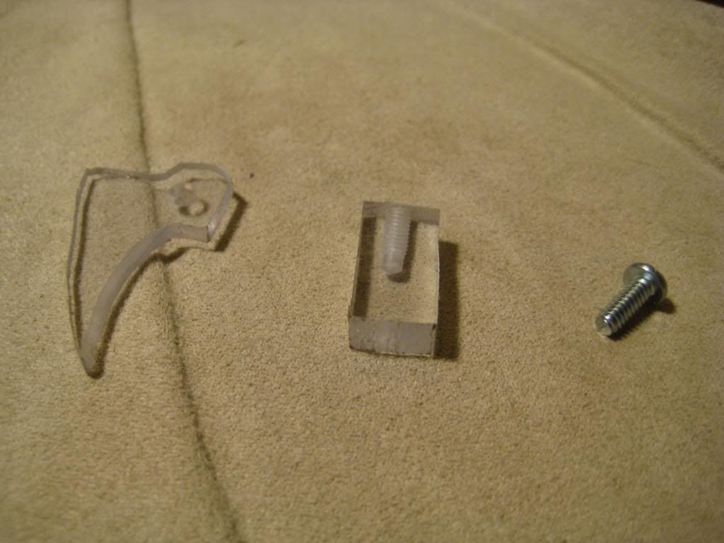
The piece of polycarbonate is 3/8'' wide and 7/8'' tall. It has been drilled and tapped with the 7/64'' drill bit and goes here:
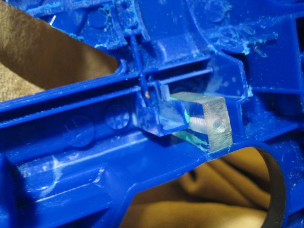
The rest is simple:
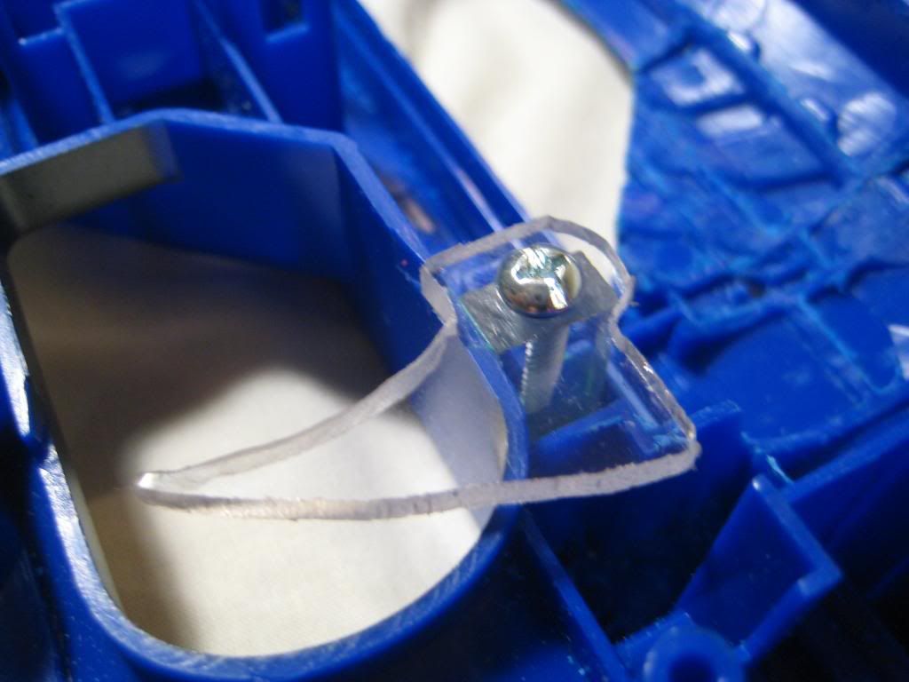
And the rest is history! Put it all back together (without forgetting the rail mount pieces) and marvel at what the Longstrike wished it could always be:
Cutaways are nice, so you can see full compression in action!
Conclusion:
Damn, what a blaster. It seems like even a 16'' barrel is no problem for this bad boy. With over 7'' of draw, this thing could actually put an eye out. Many thanks to Obi, the modder I followed--you are a gentleman, scholar, and general baller. Hopefully this writeup brings hope to those who have lost faith in the Longstrike. One thing I could have done better was move the priming handle closer to the plunger tube to avoid face-diddle, but it may be unavoidable with over 7'' of draw. Here is the average velocity:
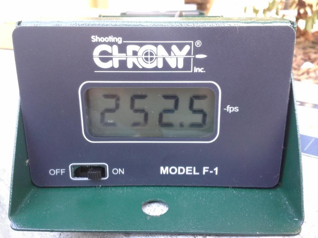
Not bad, considering the plunger head is too fat. Perhaps my 16'' barrel was too short as well--I'll have to make a 2-footer for blasters like this! In any case, I'll be revisiting this blaster farther down the road for one final mod--a shotgun grip
Cheers,
~T
I browse the forums fairly regularly and sometimes I see something that really impresses me. In this case, it was actually a Longstrike! It's not often you get all hot and bothered by a blaster that absolutely blows stock. However, nowadays I see blasters in a different light than I used to. Now that I have the means to create any of my own components, there's no point in reusing Hasbro's internals at all. A blaster's worth to me is now measured in how good it looks and how easy it is to incorporate internals and other goodies. The Longstrike satisfies all my requirements, and just happens to have enough room for a 1.5'' PVC plunger tube! This mod is literally a wolf in sheep's clothing--the shell is the only thing left that's actually stock.
Here's the Longstrike I got for free:
The bolt was stuck, so the owner probably tried to open it up, realized it was solvent welded, and gave up. Sweet!
Required Materials:
- 1.5'' clear PVC pipe
- 6-32 threaded rod
- 1 1/4'' to 1/2'' PVC bushing
- 6-32 Keps nut x4
- 3/8'' length 6-32 set screw x4
- 1/2'' length 6-32 set screw x2
- 1/4'' polycarbonate sheet
- 1/8'' polycarbonate sheet
- 6-32 nylon spacer x2
- 3/4'' length 6-32 screw x4
- 6-32 shoulder screw
- Small, strong spring for catch
- [k26] mainspring
- 1/2'' round Delrin rod
- Spud gasket (for toilets)
- 1'' length 6-32 screw
- 3/8'' length 6-32 screw
- #6 washer
- U-cup or piston cup ()
Required Tools:
- Scroll saw
- Screwdriver
- Drill press
- Hand drill
- Dremel
Write-up:
Let me start out by saying that taking apart this blaster can be a huge bitch. There were orange pieces randomly solvent welded into place that actually kept the two halves of the shell from separating. Suffice it to say, I ended up using the Dremel as a samurai sword and severing anything in my path. I think it's a conspiracy by Hasbro to prevent people from modding blasters with too much real estate inside them. Anyways, eventually I cracked the egg. Start by cutting the plunger tube. It should be a whopping 14'' in length:
Now to prepare the front bushing. I secured the bushing in between two fender washers, tightened nuts on both ends, and put it in the drill press.
I used my "ghetto lathing" method to shave down the bushing with a Dremel until it fit nicely into the plunger tube. Use some PVC solvent to permanently attach the bushing with an airtight seal:
Now for the worst part of the mod--Dremeling the shell to fit the plunger tube. You can make things a little easier by cutting out the gloryholes that I did:
Dremeling the shell proved so frustrating that I even forgot to take a picture of it. Just keep checking the fit with the plunger tube until it fits. The front of the plunger tube should be flush with the front of the shell as well. Anyways, let's finish up the plunger tube. This requires the construction of a Rainbow Catch. I did a write-up on how to make a 1.5'' Rainbow Catch with no templates here.
Stick it in the back of the plunger tube and mark where the shoulder screw will pass through. Drill the hole with the 5/32'' drill bit, then use a small screw to hold the catch in place for more drilling.
Drill four holes with the 7/64'' drill bit through the plunger tube and into the inner ring of the catch. Tap them all.
Now that the rear end is prepared for duty, it's time to put the threaded rod through the front bushing. Drill through with the 7/64'' bit, tap, and insert the threaded rod. Drill 9/64'' holes in the shell at the front for the threaded rod. Add glue around the threads to prevent air leakage. Fail to do this and you won't get the perfect seal!
Put the plunger tube in place and enclose it in the shell. Then drill a 7/64'' hole through the shell and plunger tube on either side towards the rear of the blaster. Expand the holes in the shell with the 9/64'' bit. This step is just to insure that the plunger tube has adequate support.
Last order of business is plunger padding. I used a healthy amount of toilet gasket to kill some dead space and insure that the blaster doesn't destroy itself:
Now on to the plunger rod. Cut a 14'' length of Delrin rod and drill (and tap) one end of it with the usual 7/64'' drill bit.
Here is my plunger head. From left to right: 1'' screw, #6 washer, 1/4'' polycarbonate disc, <1/4'' polycarbonate disc, U-cup, 1/4'' polycarbonate disc.
In order to prime the blaster you need to fabricate something here is what I made:
I attached it to the end of the plunger rod with a couple of 3/4'' screws. Later I ended up trimming down the sides, since I was getting some facerape holding my head against the stock while firing.
Here is the plunger rod assembled. As you can see, my U-cup was a bit large. Regardless, the seal is perfect. I have discovered recently that 1.5'' OD piston cups plunger heads are the ideal choice for 1.5'' PVC.
Don't forget to Dremel the back of the shell for the new priming rod:
Put the assembly in the blaster and get a friend. Prime the blaster all the way back and get a friend to make a mark right where the rod leaves the shell. The front of the catch notch will be cut 3'' in front of the mark:
Reassemble everything again, and we're almost through! Here are some shots of the completed plunger tube:
Now for the final challenge--making the trigger! Obi, the original creator of this mod cautioned that this would be the hard part, but I thought about it for a while and arrived at a simple and elegant solution. First, a piece of the shell must be trimmed in order to accommodate the trigger:
Here are some tentative schematics I used for the trigger. The final product was a bit taller and wider:
Here is everything needed for the trigger setup. The trigger is 1/8'' polycarbonate, the mount is 1/4'' PC, and the screw is a 3/8'' screw.
The piece of polycarbonate is 3/8'' wide and 7/8'' tall. It has been drilled and tapped with the 7/64'' drill bit and goes here:
The rest is simple:
And the rest is history! Put it all back together (without forgetting the rail mount pieces) and marvel at what the Longstrike wished it could always be:
Cutaways are nice, so you can see full compression in action!
Conclusion:
Damn, what a blaster. It seems like even a 16'' barrel is no problem for this bad boy. With over 7'' of draw, this thing could actually put an eye out. Many thanks to Obi, the modder I followed--you are a gentleman, scholar, and general baller. Hopefully this writeup brings hope to those who have lost faith in the Longstrike. One thing I could have done better was move the priming handle closer to the plunger tube to avoid face-diddle, but it may be unavoidable with over 7'' of draw. Here is the average velocity:
Not bad, considering the plunger head is too fat. Perhaps my 16'' barrel was too short as well--I'll have to make a 2-footer for blasters like this! In any case, I'll be revisiting this blaster farther down the road for one final mod--a shotgun grip
Cheers,
~T
T da B's Firestrike Overhaul
08 June 2013 - 03:55 AM
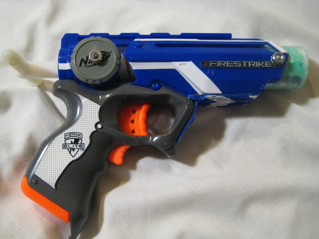
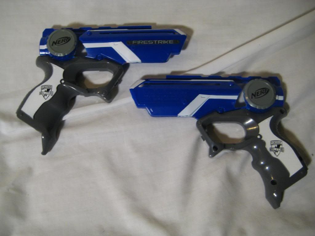
Sup guys,
It seems like the Firestrike is a pretty popular new blaster nowadays and a semi-worthy replacement for the Nite Finder. A few weeks ago I decided that I wasn't showing pistols enough love, so I decide to take one to the absolute max. This mod is one of my finest to date, and I went through a lot of trouble to get this thing functional. Here are some of its wonderful properties:
- 1 1/4'' polycarbonate plunger tube
- Delrin plunger rod
- 4 1/4'' [k26] at full compression
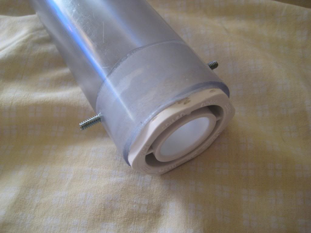
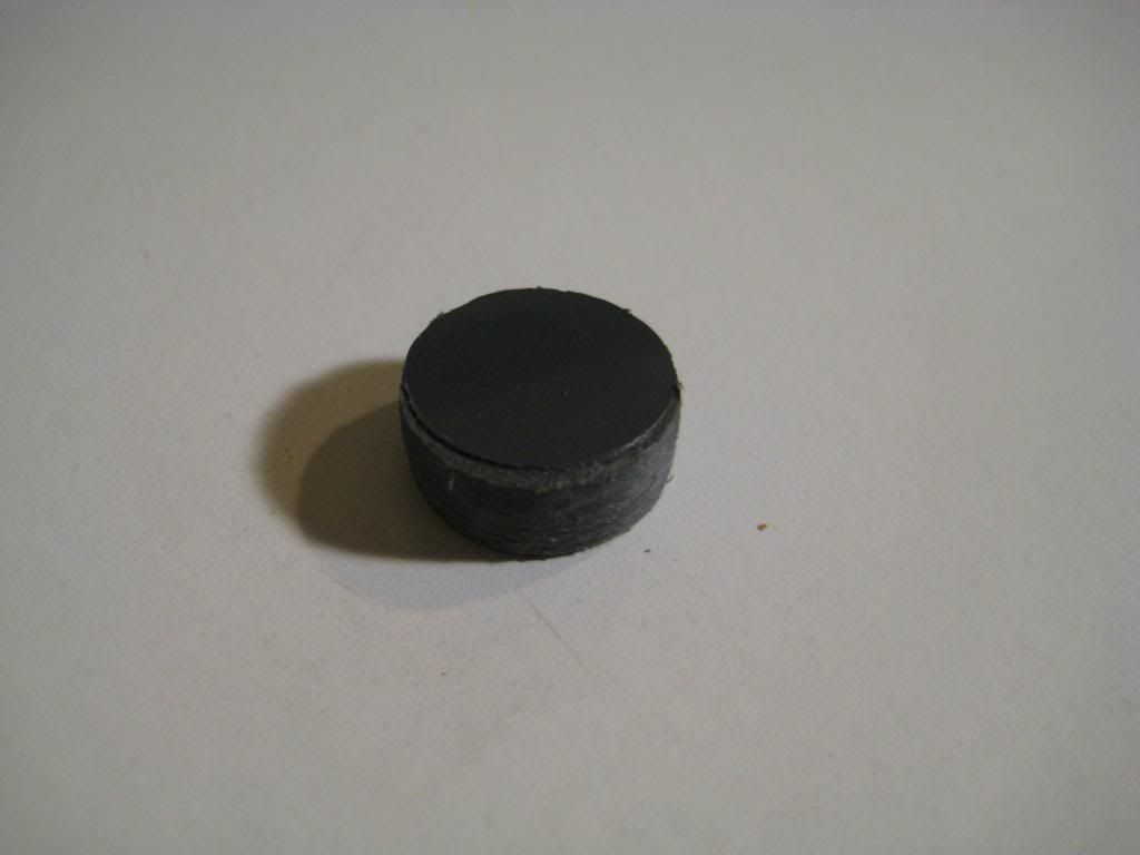
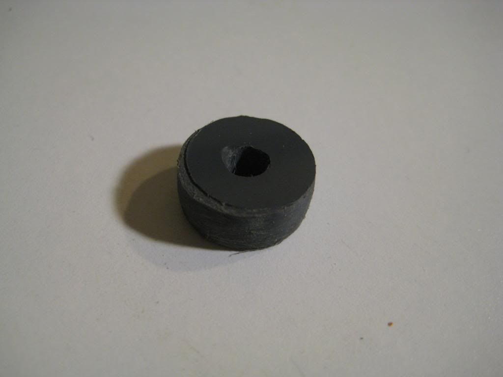
- 1 1/8'' rubber grommet seal
- Custom front spring spacer
- Custom rear spring blocker
- Custom trigger catch
Required Materials:
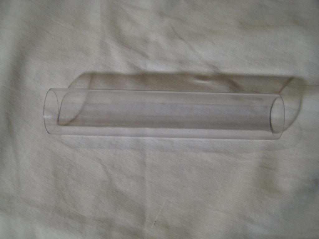
- 1 1/4'' diameter polycarbonate tubing
- 1/2'' PVC coupler
- 1/4'' PVC sheet
- 3/8'' Delrin rod
- 1'' 6-32 pan-head screw
- #6 washer
- 3/4'' fender washer
- 1'' fender washer
- 1 1/8'' O.D. rubber grommet
- 1/4'' polycarbonate sheet
- 1/8'' polycarbonate sheet
- 3'' 6-32 threaded rod x2
- 3/4'' length, 3/8'' thickness 6-32 nylon spacers x2
- 6-32 nylon acorn nut x2
- PVC/ABS solvent
- 1/8'' natural gum foam
- 1/2'' I.D., 5/8'' O.D. polycarbonate tubing or CPVC
- 1/4'' 6-32 set screw
- 3/8'' 6-32set screw x3
- 1/2'' 6-32 set screw x2
- 6-32 Keps (K-lock) nut x4
- Replacement catch spring
- [k26] mainspring
Required Tools:
- Scroll saw
- Dremel
- Drill or drill press
- 6-32 tap
- 3/4'' hole saw
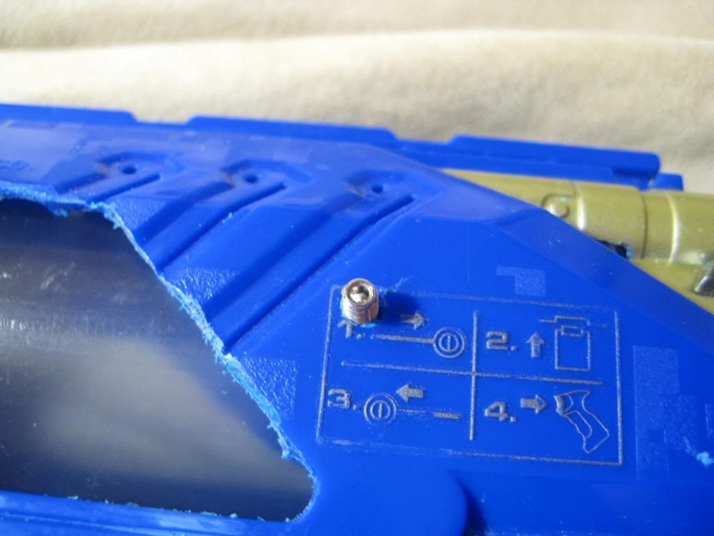
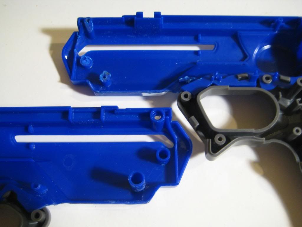
Start by gutting that bitch:
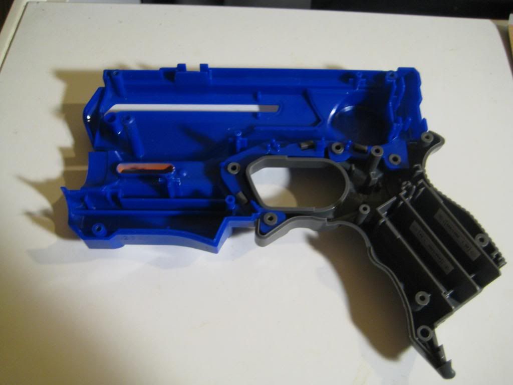
Undo the gray tabs holding the two halves together to separate the shell:
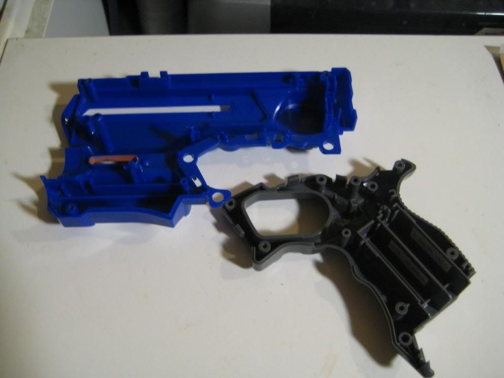
Now Dremel off the part the houses the light unit. Do it cleanly, as you will be reusing it!
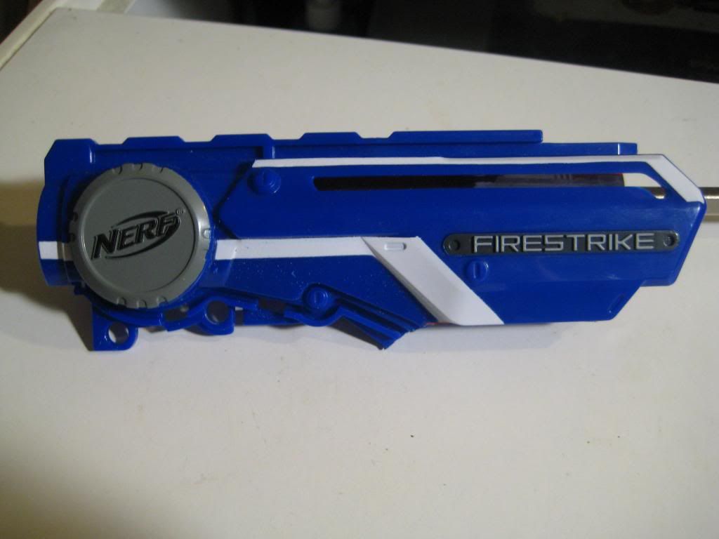
Here are the pieces you will need from the light unit:
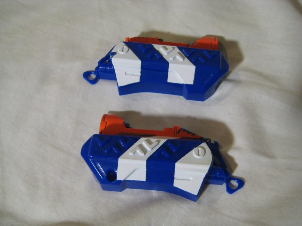
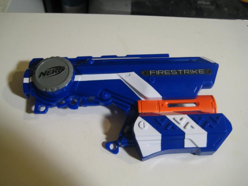
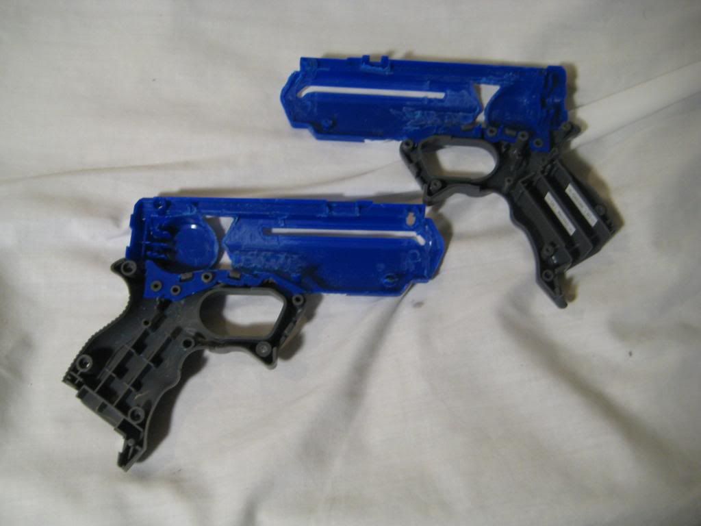
Snap the shell halves back together:
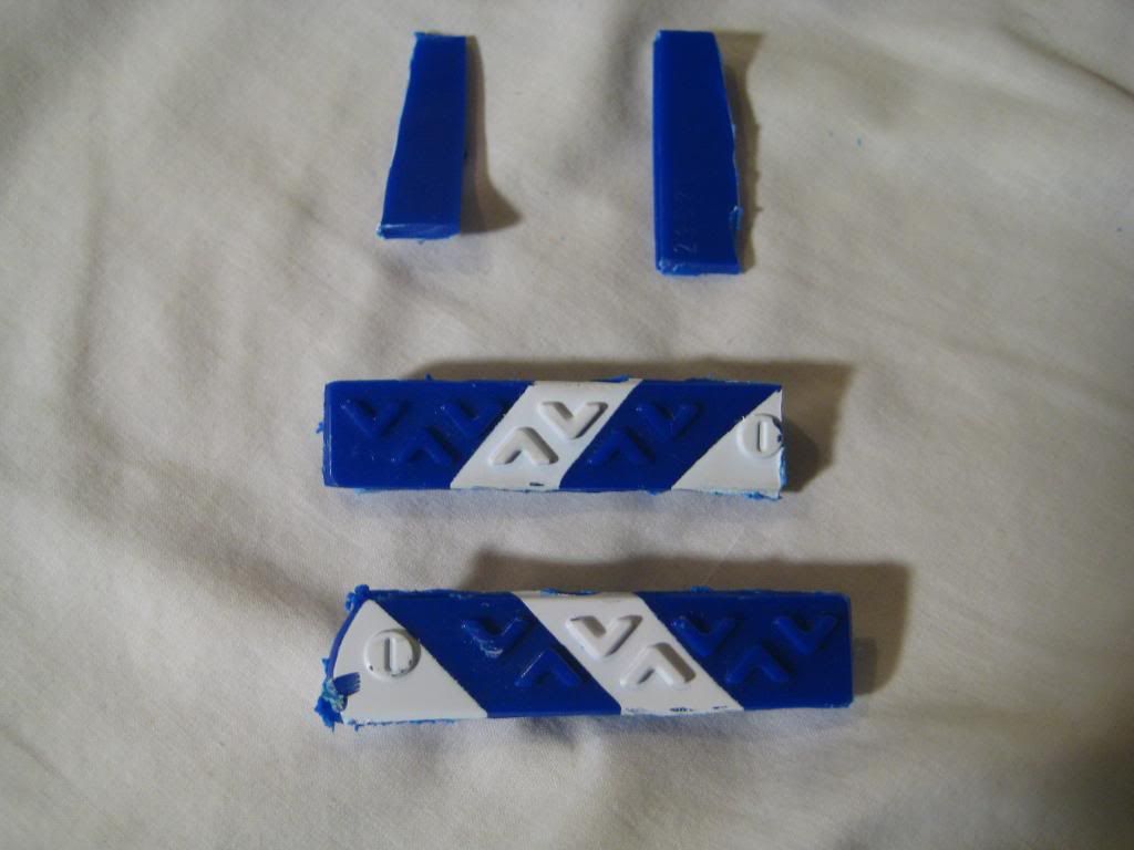
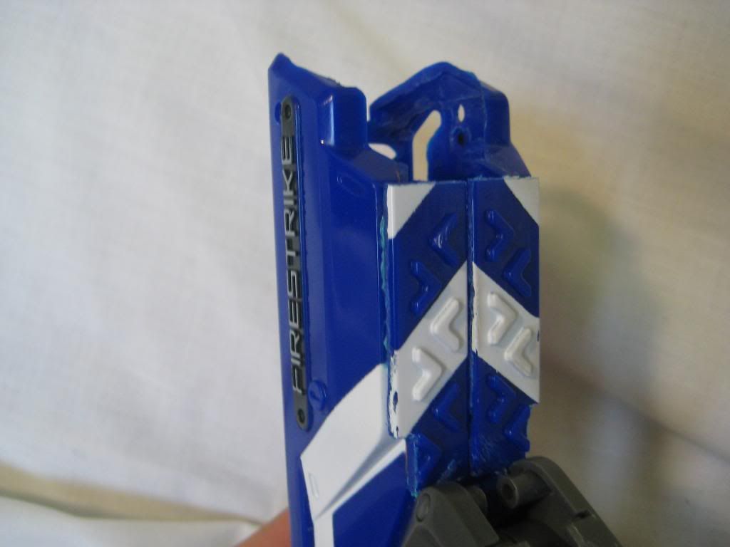
Now to cover the gaps in the shell--chop down the two striped pieces from the light unit like so:
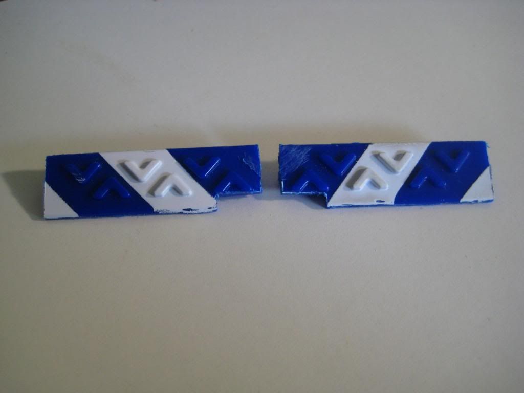
Then use the PVC/ABS solvent to weld it to both halves of the shell. Notice how I lined up the stripes--yes I am OCD like that sometimes!
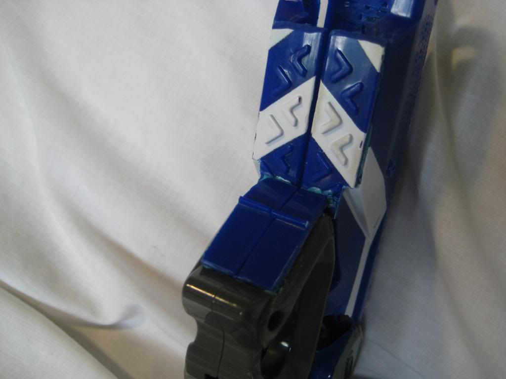
Trim down the other two pieces:

And attach:
At this point it would behoove you to cut the plunger tube. 6'' is the length I went with--just long enough to keep the pistol compact:
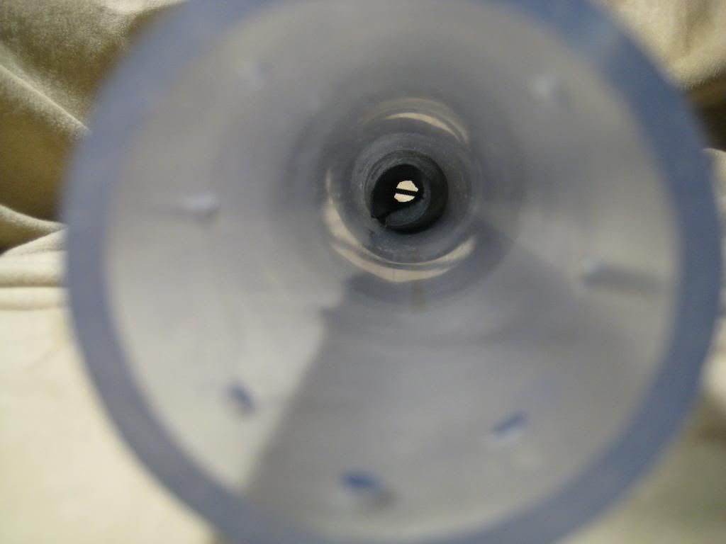
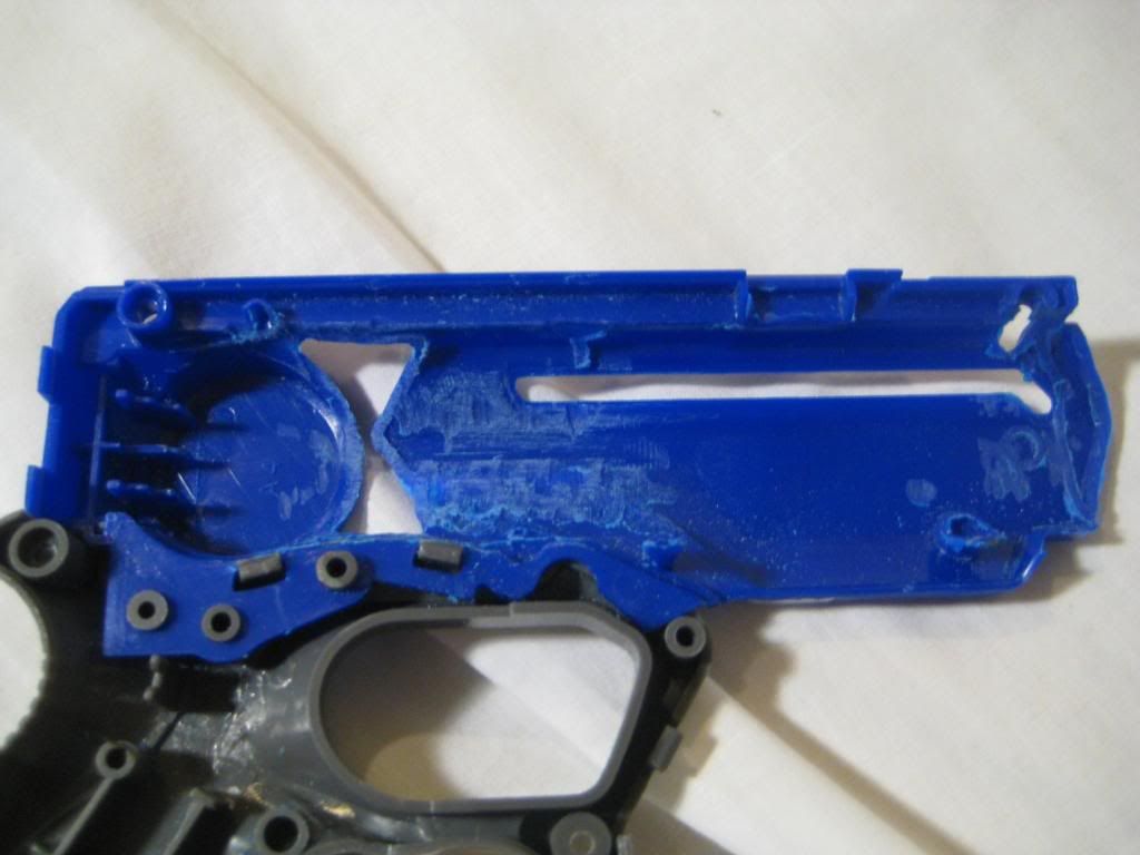
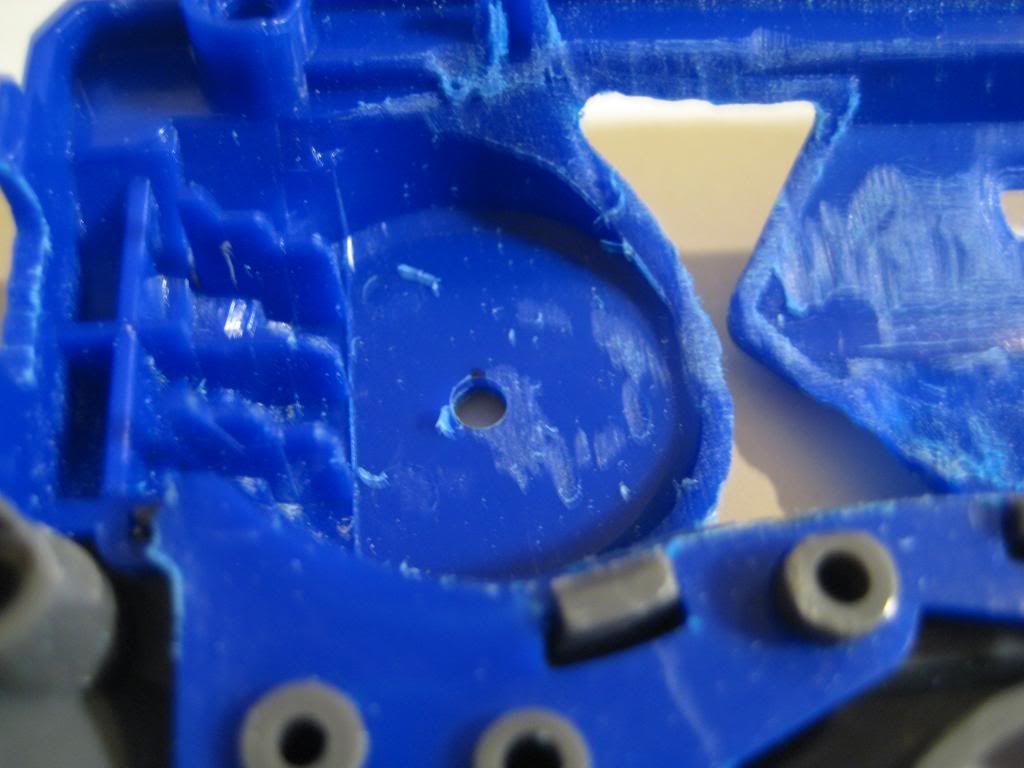
Now for one of the most time-consuming parts of the mod--Dremeling the shell down to the fit the plunger tube. Use the plunger tube to constantly test the fit. The part right in front of the round section with the Nerf logo gets Dremeled so thin that I just cleared it out to look like an hourglass on both sides. One tip I can provide is to look straight down the front of the shell and look for a perfect U-shape all the way back to the rear of the shell.
At this point let's tackle the plunger tube. Cut down a 1/2'' PVC coupler and leave enough room for a 6-32 threaded rod to pass through:
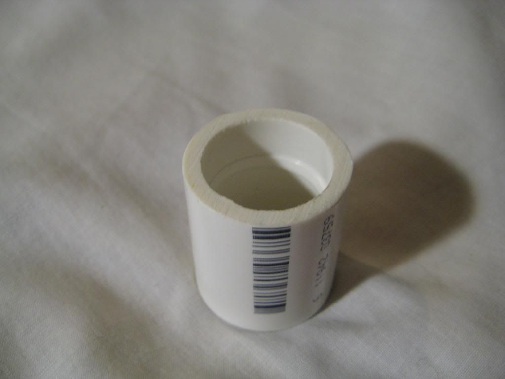
Use the PVC/ABS solvent to permanently weld the coupler into the end of the plunger tube. As it turns out, the fit is perfect! Use a lot of solvent, as the seal must be airtight. When the solvent cures after a day, drill through the plunger tube with a 7/64'' drill bit and tap it with the 6-32 tap:
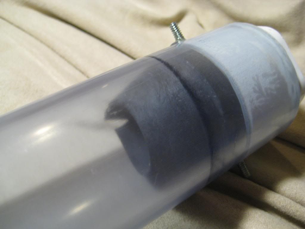
Insert the 6-32 threaded rod through the plunger tube. I used two hex nuts and tightened them together. Then I used a wrench on the rear nut and threaded it through:
Before the next step, you will need to drill some holes in the shell. The purpose of the holes is the support the force of the plunger rod, as you will see later. Here is where I drilled my holes--they are perfectly in line with the middle of the plunger tube:
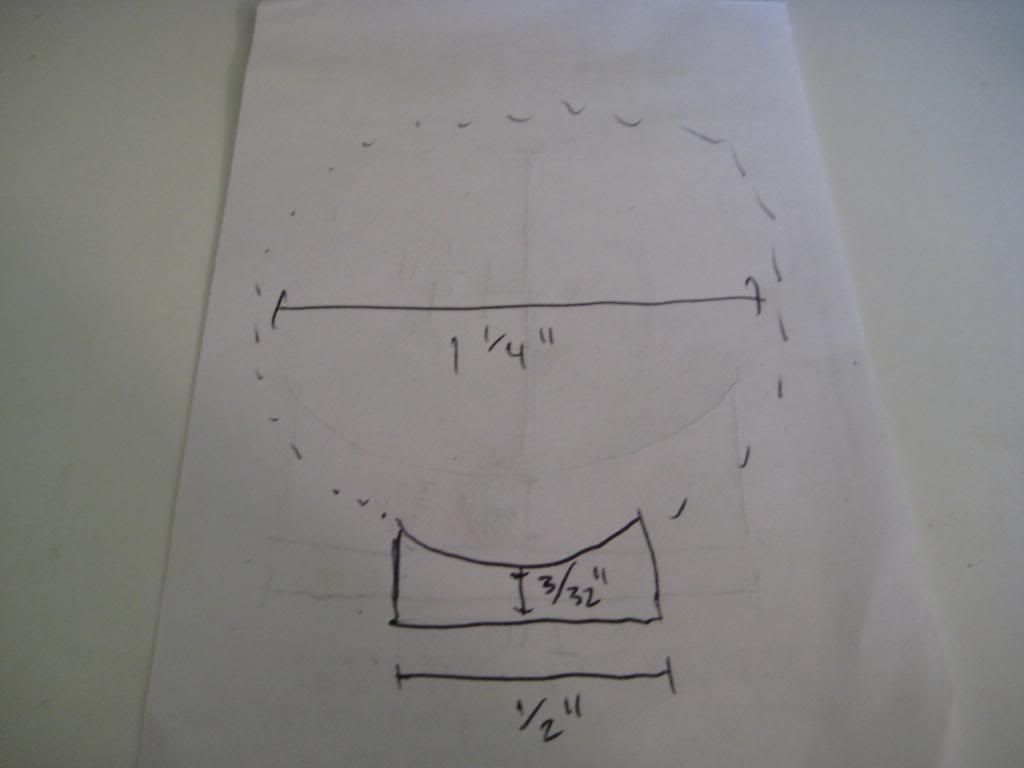
You will now need to fabricate the rear plunger tube supports. They will be made from 1/4'' polycarbonate and follow this schematic:
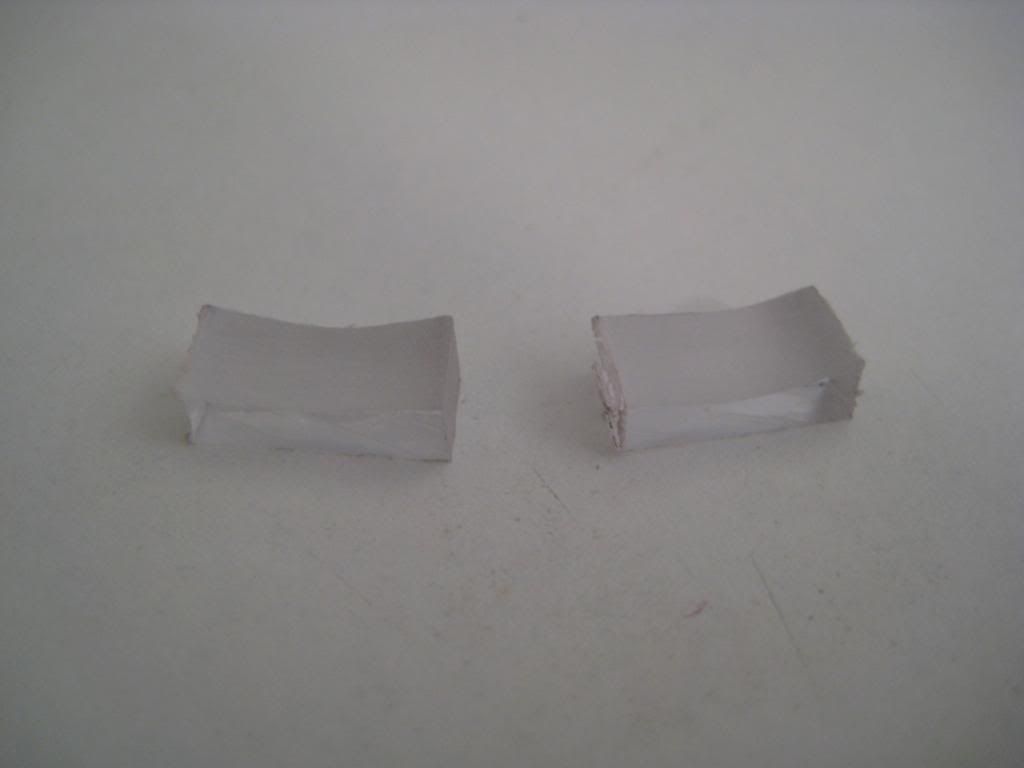
Here they are!
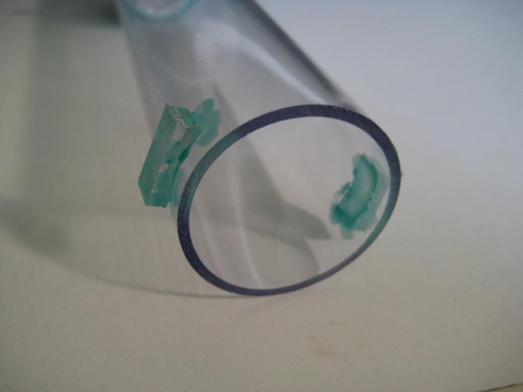
Now take plunger tube and put it into place and close the shell. Make a mark on both sides through the rear hole on both side to designate a spot of importance. Then take your polycarbonate pieces and solvent weld them into place:
When the solvent cures, put the plunger tube back in the shell and close it up. Make two marks just like before--through the back holes. Drill and tap through the marks you made with the 7/64'' drill bit and 6-32 tap:
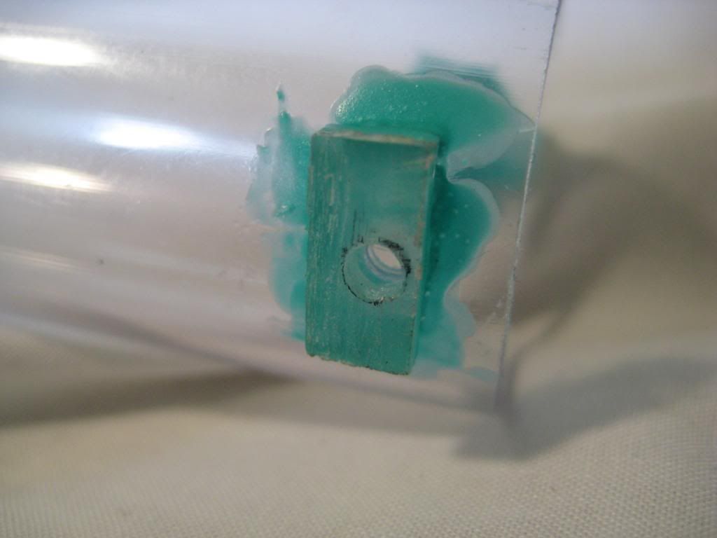
I forgot to take a picture of it, but you should insert a 1/2'' set screw into each of the holes you just made. Make sure that they don't protrude into the plunger tube or the spring will get snagged! The final step for the plunger is to cut yourself some plunger padding and insert it down behind the 1/2'' PVC coupler:
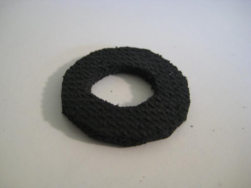
Next up is the plunger rod. Take your 3/4'' hole saw and cut a circle out of your 1/4'' PVC sheet. This will serve as a spacer that sits inside the rubber grommet:
Drill a 9/64'' hole right through the middle:
DO NOT POST! THIS WILL BE A TOTAL OF 2 POSTS!

