 Find content


Thank you Doom and Langley. I've been on Nerf withdrawals and having to sustain my fix on [shudder] Facebook Nerf groups these past weeks. It's good to have you back, darling.
Aeromech
Member Since 19 May 2011Offline Last Active Sep 04 2017 09:55 PM
#355878 And we're back....
 Posted by
on 20 September 2016 - 12:31 PM
Posted by
on 20 September 2016 - 12:31 PM
#355769 Modification and Paintjob Pictures
Posted by
on 24 August 2016 - 04:21 PM
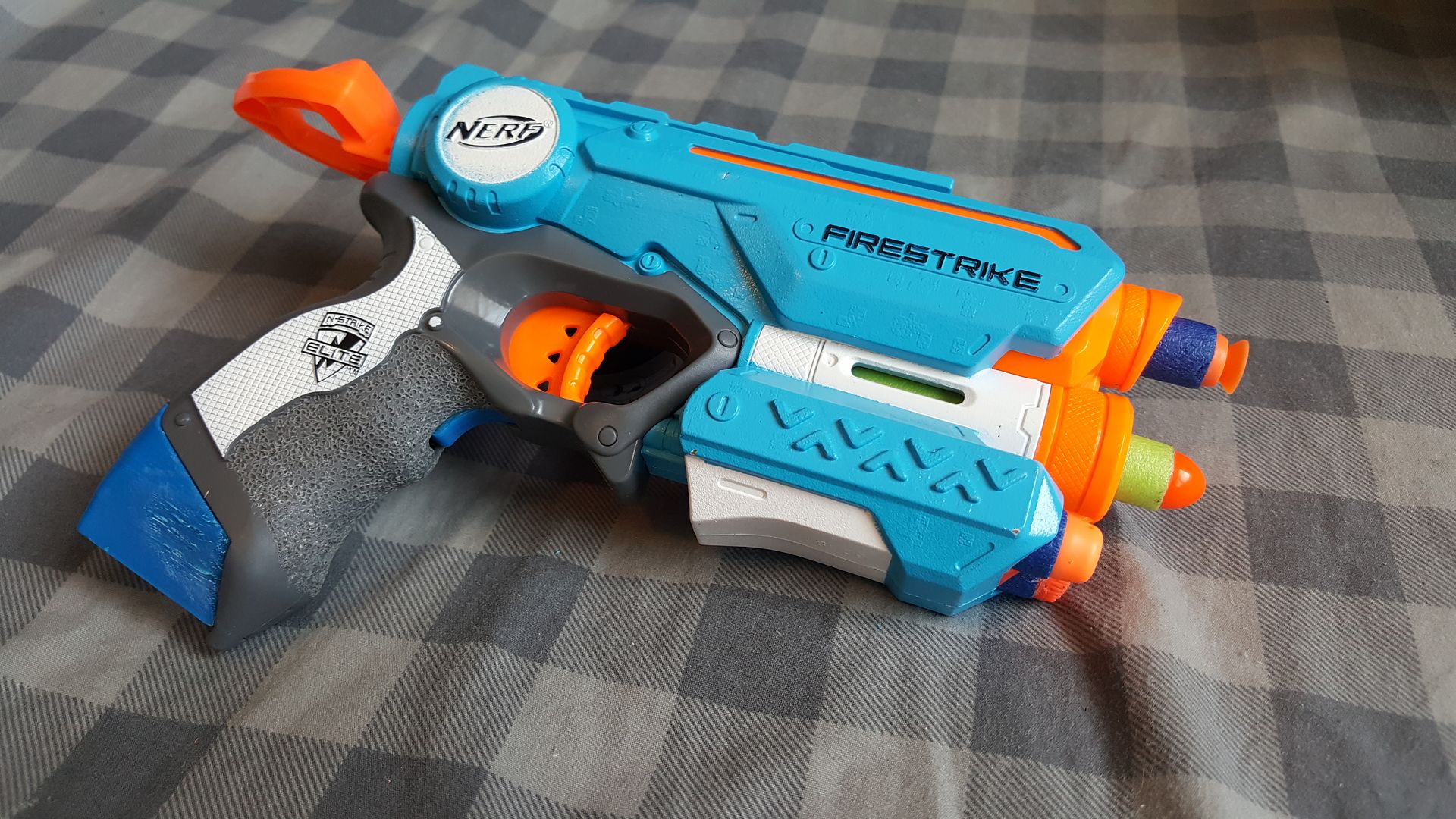
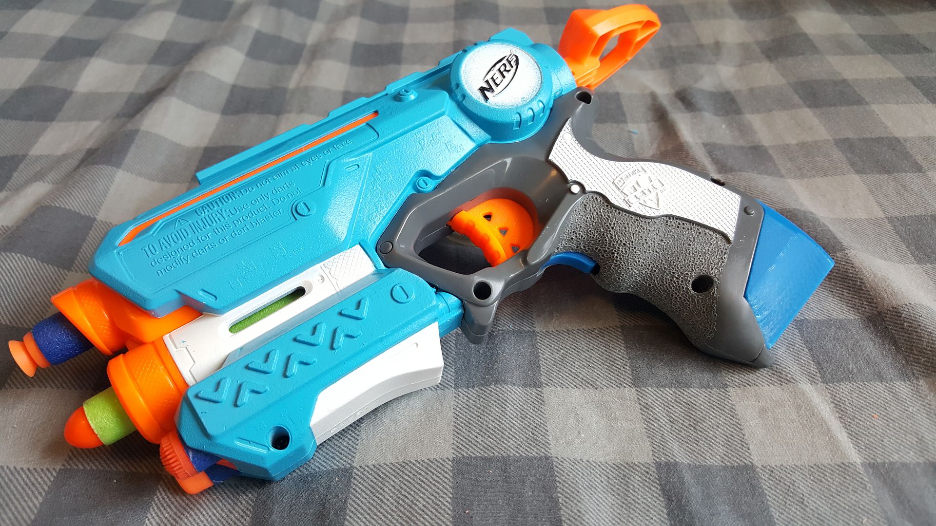
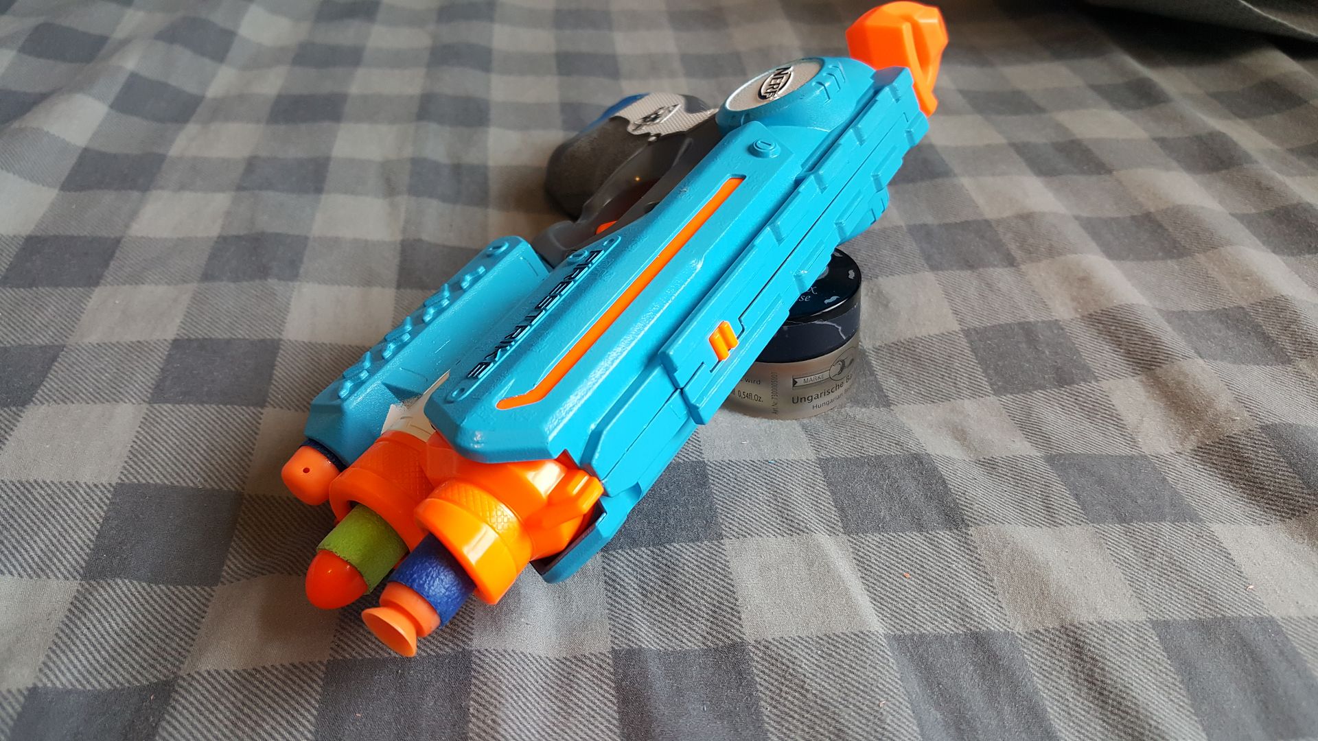
Aeromech themed Firestrike. Didn't finish sanding the 3D printed grip extension, it looks cheese in the photos but its smooth as anything now.
#355175 Sear Carbine Writeup
Posted by
on 24 July 2016 - 10:34 AM
The idea of using some type of sear to lock a bolt in place has been used on real-steel firearms since the advent of the machine gun, due to the simplicity and self-locking action of the mechanism. In the homemade Nerf market, this is a relatively new field, first being implemented on the ESLT some years ago. This is my attempt to marry SNAP style redneck engineering with the aforementioned locking mechanism.
RULES:
-No McMaster/Online ordered parts (Barring a [k25] spring, Good luck finding 11" long springs at a hardware store).
-No special tools required (No long-shank countersinks, holesaws, or any of that)
-No 3D printing
-Keep weight as low as possible
TOOLS:
-Rat-tail file
-Pocket knife
-Electric Drill with standard bits (no larger that 1/2")
-Woodsaw
-Hacksaw
-Screwdriver
-Sandpaper
SUPER HELPFUL BUT NOT NECESSARY
-Belt sander
-Drill press
-Table saw
-Vice
For this Writeup, descriptions will be BELOW the photos they reference.
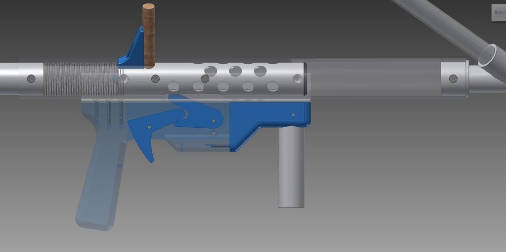
This was the original idea, using 3D printed components. I wanted to do the same thing without limiting myself to 3DP parts. But this is the idea. Borrow an ESLT/submachinegun catch and use it in place of the fickle SNAP nail and clothespin catch. Insert anecdote of "my SNAP shoots like 150 feet and I've never ever lubed it or replaced anything on it ever" but I have built three and they have ALL failed within 100 shots. Stop trying to convince me. Unless there is some kind of drastic improvement in the design I will not endorse SNAPs as being consistently war worthy. Moving on...
The actual catch mech can be seen here. a slot through the body tube and bolt allows a catch finger from the sear to rotate upward and extend into the bolt slot, blocking the bolt from moving forward, when the trigger is pulled, it pivots the sear downwards and the catch finger moves out of the bolt slot, and the bolt flies forward under spring force.
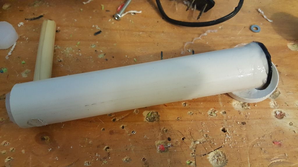
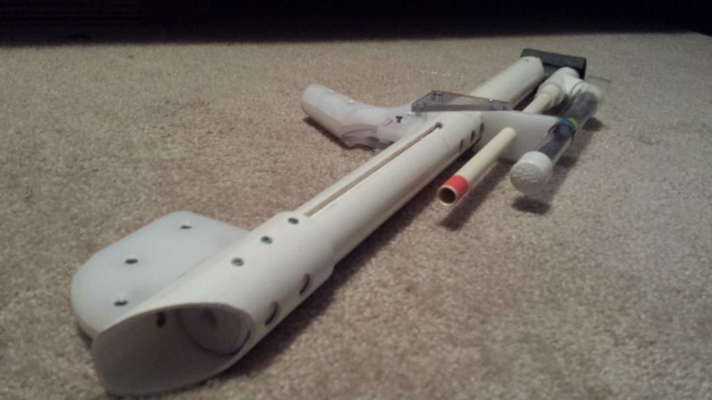
This is the bolt. It is made of 1" PVC, with both ends capped off by cutting board. Get the fat kind, from Walmart, It's $6 and is like 1/2" thick, really great stuff. This bolt is about 7 inches long.
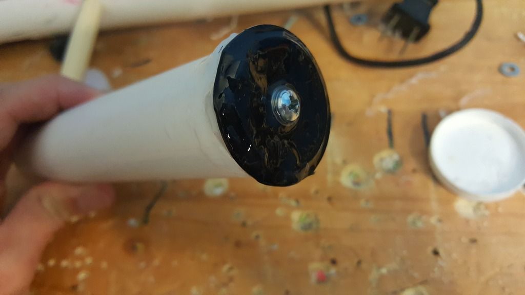
Superlative plunger head screwed into the front. Actually provides a really good seal on this thing.
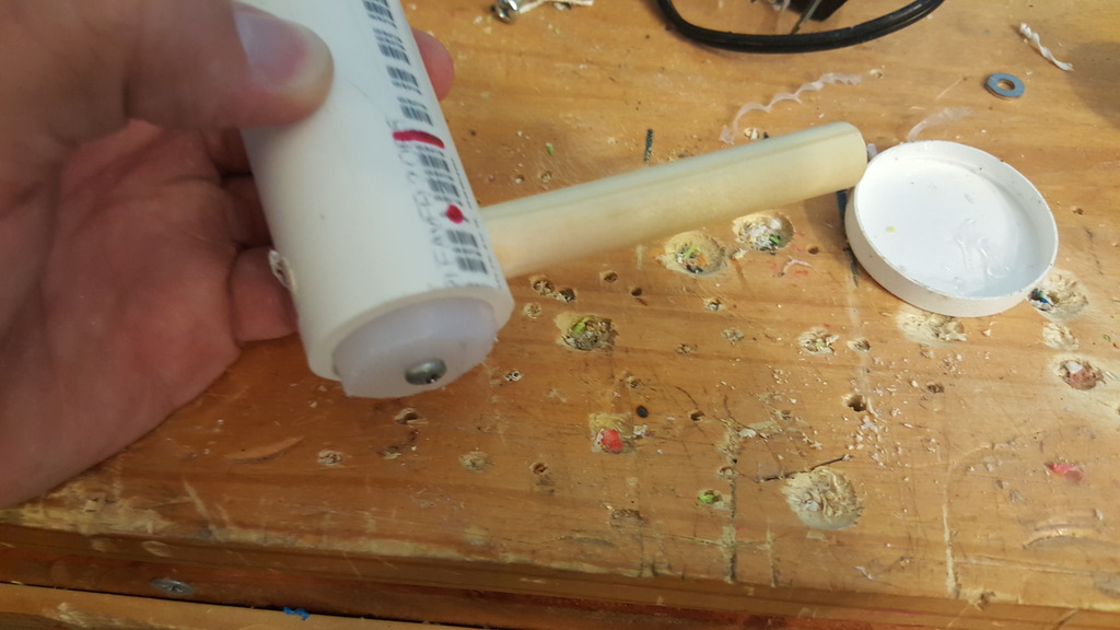
The back shows a 1/2" dowel sunk into the tube, with the rear cap held on by a screw into the dowel itself. I cut the bolt too short so the cutting board is sticking out, but yours shouldn't stick out.
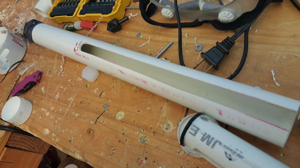
Pretty standard at this point. Gooped in front bushing, with a slot cut 6.5 inches away from the front, running all the way to the back.
This is an anti-kinking device (1" PVC pipe beveled internally at one end) duct-taped directly to a 1" to 3/4" bushing.
We've all done the thing where we reach into the hardwre store bin without looking and get home with a 3/4" bushing and not a 1/2" bushing. Now is the time to use it.
Now we need to make some decisions. Decide the orientation you want your bolt to stick out. It should probably be at least 45 degrees up from the horizontal. Drill holes all around to lighten it up, but do not drill holes on whatever the "bottom" side is. On the bottom, make a slot about 2 inches long right at the front of the bolt. This is where the catch will lock. Make it wider than it needs to be, it will be much less finicky if this hole is oversized.
Test fitting with the [k25].
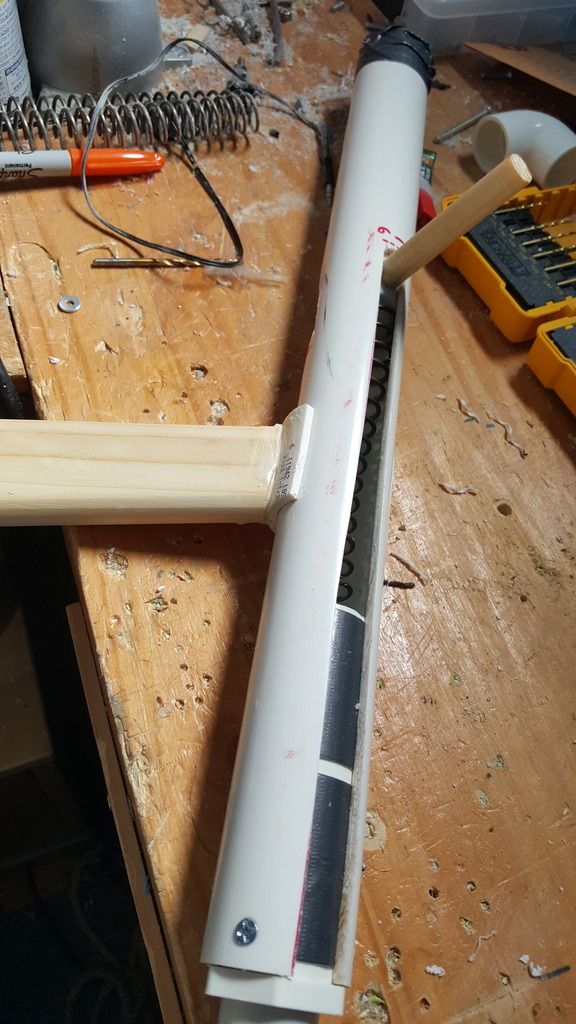
Testing with the new handle. I used a 1-1/2" PVC "half piep" (really more like a 2/3 pipe) to snap directly onto the barrel. Note the stylish wooden handle that SNAP users seem to love. You can also just barely make out the hole in the bottom of the body tube; this should match up with the slot that was cut into the bottom of the bolt, so the catch can have access to the bolt slot and lock in place.
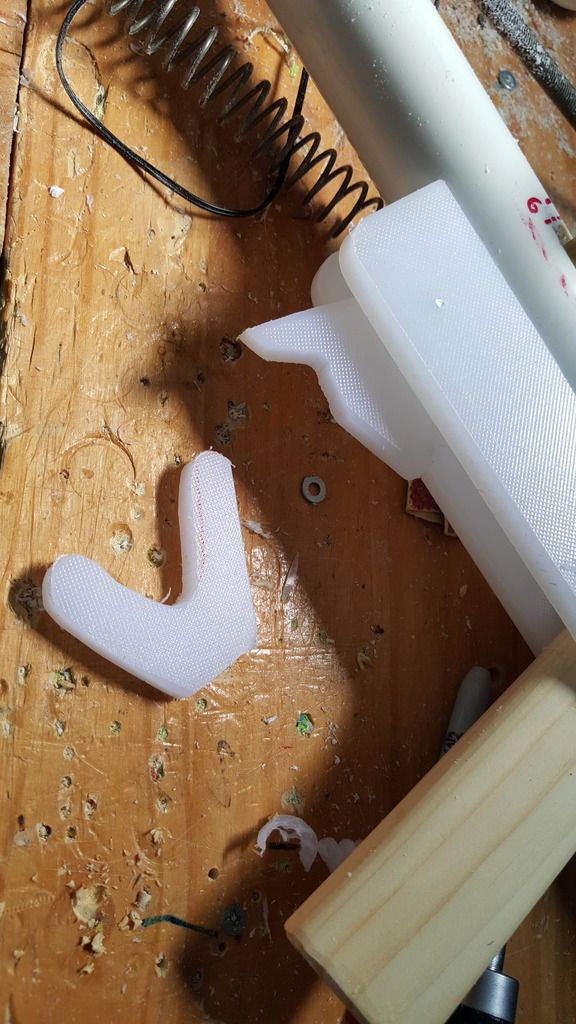
This is the guts of the catch, with cutting board sideplates holding everything in. Basically, the trigger is pulled, which rotates the catch itself downwards and out of the way of the bolt. The catch itself is triangular shaped and really just has a piece which pops up into the body tube and locks into that hole in the bolt. Just like an ESLT, make sure you made a slot in the body tube as well that lines up with the bolt slot.
The 3/4" bushing in the rear makes it almost trivially easy to throw on a stock, and the 3/4" pipe is much stronger than the 1/2" pipe. Rubber bands act as the catch restoring mechanism, and create a spring loaded trigger too. The front of the sideplates are held on simply by zip ties.
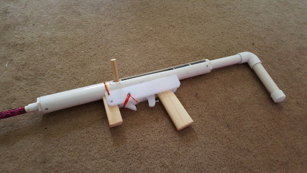
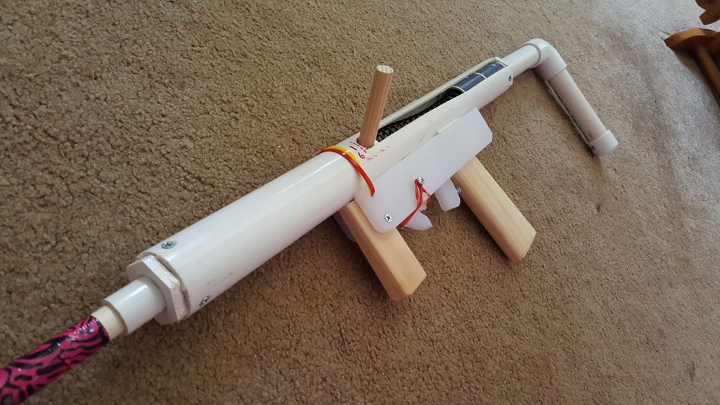
This baby is pretty asymmetrical, but I kind of like it that way. The spring kinks up a little, but the anti kinking mech fixes that without using any guide rods. The spring is not reaching full compression (need to chop another half inch off the back) but has like an inch or so of precompression, gets 5.25 inches of draw with the [k25], and rocks roughly 200 FPS based on just ear-analysis, I want to test it at APOC and get hard numbers.
The blaster without a barrel and hopper weighs 1 pound, 15 ounces, so with a barrel and hopper probably around 2.5 pounds, and even that weight can be brought down if you used wooden sideplates or went ham on lightening holes, particularly in the rear where the anti-kinking tube is.
Overall, I am mildly impressed with the blaster. A hardware store hitter that can play with the SNAPs with sear reliability and without the need to order anything. Get a pack of springs from spiderbite and you're set.
#354333 Fix for Omni-directional Plunger Rod Binding/False Catching
Posted by
on 18 June 2016 - 04:04 AM
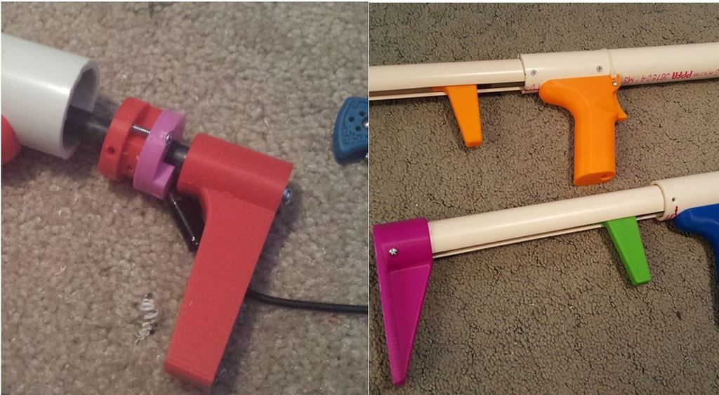
So my distaste for omnidirection plunger rods is not unknown to the nerf community, up til now, they seemed to catch less reliably than unidirectional catches, and were overall more fickle. The problem comes down to spring binding issues, particularly with the [k26], and maybe even the [k25]. As the plunger rod is pulled back and the spring compresses, it does not compress perfectly in line with the plunger rod, and tends to "serpentine", getting all wavy and kinky before it reaches it's final stage of compression. During this time, the spring gets caught in the omni-directional catch part of the plunger rod (with the lower rod diameter) and produces either a VERY unpleasant "crunchy" feeling to the prime, and often results in a "false catch" where the spring actually gets caught in that catch region when you pull the plunger rod back. You think the catch has engaged, and as soon as you begin to let go, and the spring is able to exert it's energy, the plunger assembly flies forward. This leads to swearing, sore fingers, questioning your rainbow catch-making abilities, and an overall hopeless feeling knowing that this lifeless piece of plumbing pipe has defeated you. You're better than that mate. Millions of years of evolution have prepared you for this moment. It's time to take on that omnidirectional plunger and make it yo bitch.
The "Before" photo. Here is a pullback with the main tubes "ghosted" out, so the insides are visible but you can still see the outline of the body tube. Typically, the spring binds in the recess near the front of the plunger rod, where it is supposed to engage in the catch.
This is it. This is the easiest solution ever. Cut a piece of 1" PVC Pipe, about 2.5 inches. Make sure it is shorter than the spring at full compression, but not too much shorter. Get it close, but make sure it is still shorter. Take note that the front (left side of the photo) of the tube is beveled on the inside. This is important. Put a few wraps of packaging tape around this so it fits fairly snuggly inside the 1-1/4" PVC plunger tube.
Boom. Throw it in there. Rest this piece against the front of the rainbow catch, with the beveled end facing forward. Sink two screws in there to hold it in place.
This photo provides a little more insight, the anti-binding pipe goes around the spring. When the spring is compressed, it is "guided" to a more "cocentric" position within the body tube. The bevel smoothly pushes any parts of the spring that may bulge out into position, so the spring cannot bend to the point where it would interfere with the catch region of the plunger tube. After installing this into a rainbow pistol/carbine (5 inches of draw, like 1 to 1.5 inches of precompression, 10 inches of [k26] spring) all false-catches stopped completely. The prime was smoother, and all the problems I was having with the catch vanished. It caught every time, and smoothly. Follow this guide if you're using a [k26] in conjunction with an omnidirectional plunger rod.
Make sure it doesn't cover up your speed holes (anti vacuum holes). Once you sink in this piece, just re-drill the speed holes in the main body tube through the anti-binding pipe you just installed. Super easy.
#354018 Definitive Guide to 3D Printing
Posted by
on 06 June 2016 - 11:58 PM
Speaking of beds, I bought the glass plate and am using blue painter's tape. I tried hairspray and didn't get results, so it was one of the many variables I changed all at once. The blue tape works great, but my problem could have been bed leveling. That stuff is super critical - get a sheet of regular printer paper (typically 20# bond) and move your nozzle various places over the paper over the bed. You should need to tug the paper a bit to get it to move from under the nozzle, but the nozzle shouldn't tear the paper or scratch the plate. It should probably dent/scratch the paper. If you're using tape, put that under the paper too.
Before I set my printer up that way, parts would come loose pretty easily and sometimes during the print. After I set my printer up that way it requires tremendous force to remove a part and my parts now have very flat, smooth, blue undersides.
I tried blue tape before, problem there is that the tape itself would peel off the bed from the force of the ABS. Glue stick glue seems to work best for me, the best thing is to keep the damn print environment hot if you're working with ABS, again easier said than done. I'll have to try PLA I guess, maybe get a spare nozzle so I don't mix filaments.
As you said, 3D print layers aren't chemically bonded. Could doing a sort of... Rubbing i guess? help with creating one? Like, taking a paintbrush with solvent weld on it and brushing it on the outside of the print to bond layers.
Short answer is no. The problem is anything that could penetrate between layers and lines of filament would melt the damn thing. Put acetone on the end of a Q-tip and touch it to a part. It will become a rubbery consistency and lose all it's accuracy. Once upon a time I tried to do this to experiment with post print repairs, but it really doesn't work, so that's why I reccommend using some super glue for parts repairs
I've heard of methods where you boil solvents under the part which smooths out the surface finish a bit. Two problems here; firstly it really is only a surface finish and there is no way to really effectively penetrate it that I know of. Plus I don't even think that you would WANT to penetrate too deep because the infill would be dissolved. Hmm, maybe I should add a section for terminology too tomorrow.
The second problem is that doing this vapor post treatment is incredibly fucking toxic. I've never died before, but I imagine it isn't pleasant, so I don't fuck with that shit. TL;DR keep your print environment warm and free of wind or drafts.
#353985 Definitive Guide to 3D Printing
Posted by
on 05 June 2016 - 02:41 PM
FOREWARD
This guide is in response to the several emails per month I receive about 3D printing, and it is easier to throw everything out there once than having to regurgitate the same information a dozen times to as many different souls. People unfamiliar with the art seem to forget that it’s not magic, and it’s not the end all answer to your homemade nerfy engineering problems, so whether you are on the fence about getting your first printer, have some ideas about a new groundbreaking 3D printed blaster, or have your own printer and need some advice in parts design or printer settings, here is a condensed summary of all my experiences to get you started. Please keep in mind the information presented here is nothing new, you can google most of this yourself and find similar results, I've never been able to find a single source with all the information I present here; I am no expert, but I do print a lot and have found a nice set of guidelines I like to follow. So think of this more like a noob’s guide to 3D printing. Chime in with your experiences too, everyone’s mileage is a little different.
1. BEFORE YOU BUY
1.1 Things to Consider
Think about your hobbies outside of nerf, how often you will realistically use your new toy, and what other applications you will (read WILL, not COULD) use the printer on. The printed products are often unsightly in their monotone colors; they will not impress your non-techy significant-other and are not really suited for furniture grade applications, however, I have printed cupboard hinges, light fixtures, and small statues with mine, and myriad other non-stress-critical applications are good places to use a printer in your everyday life.
1.2 Types of Printers and their Specifications
These consumer requirements that you have identified will lay the foundations for the specifications of your printer, most notably, the size. There are two figures to keep in mind here. Firstly, the printer dimensions. Self-explanatory, the physical space the printer will occupy on your desk, table, workbench, etc. The second is the print volume. This one is a little bit trickier and will vary based on the type of printer. “Delta” configured Printers will have a print volume that is shaped like a cylinder, and the print bed will be shaped like a circle. Most other types of traditional 3D printers, sometimes called “gantry” or “X-Y” printers will have a print volume that is box-shaped, with a rectangular shaped print bed.
1.3 Types of Printer Filament, the “Ink” to your printer
The two main types of print materials are ABS and PLA, sold as rolls of filament. Basically the “ink” to your printer, and each type has its’ own benefits and drawbacks. I print exclusively in ABS, mainly because of the relatively low melting point of PLA, and I am wary of the spooky materials sciences surrounding plastics as they approach glass transition temperatures. PLA transition temps is 70-80 °C, where ABS is 220-240°C. Read: you are probably fine with PLA, but I just prefer to be on the safe side of things, coming from a region of hot, humid summers. So this guide will focus mostly on printing with ABS.
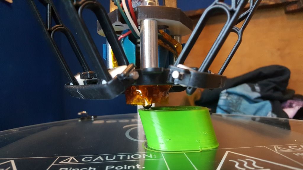
This being said, ABS is a pain to keep under control. It likes to be kept very hot and requires the use of a heated bed and adhesive to keep it stuck down while printing, seen below. Most materials, thermoplastics in particular, like to shrink when they cool down. Essentially, as the top layer of ABS cools on top of a layer that is already hardened, the top cooling layer acts like a flexing muscle, and as it shrinks, pulls up the layer underneath it. This phenomena leads to “curling” of the ABS, causing the edges of a printed part to peel off of your hot bed, and may cause delamination between layers, i.e. the separation of the layers mid-print. No bueno for stresses. We’ll get into the engineering a little later. Additionally, ABS carries more odor with it than PLA. Not necessary a bad odor, but one that you’ll have to get used to should you print in an office or something. Below, you can see the ABS on my part curling up from the bed. The glue was 2 weeks old and I forgot to wash and reapply the glue properly. Luckily, this is only a prototype part and it's not going to be going on any blasters long-term.
For PLA, a hot bed is not absolutely necessary (but still recommended), and because of its’ low melting temperature, is less likely to curl up on you, and produces less odor than ABS, but I’ve heard it is more likely to jam up in your printer, so maybe a little bit more of a maintenance hog. It is also more environmentally friendly than ABS, as it is made from plant based oils. I have far less experience with PLA, so someone else that uses it is free to chime in.
1.4 The Shit Nobody Talks About
There are so many drawbacks and inconveniences to 3D printers, and I will mention a few here and go into depth several of them in this novella. For one, TIME! I am printing a receiver for Nerf magazines for a PCSR variant, I’m only making it as a prototype, yet this 4 x 4 x 3 part is going to take 12 hours to print and it’s only a prototype part 4 layers thick! Damn, there is almost always a better way to do things than 3D printing unless your geometry is incredibly complex.
SMELL! ABS smells up your room. SOUND! I need headphones/earplugs to be able to sleep at night any more if I make any overnight prints. TEMPERATURE! If your print room is cooler than like 80 degrees, your prints will tend to delaminate and peel off the bed. TROUBLESHOOTING! DIY printers means DIY fixing. If parts break, you have to take the initiative and reverse engineer some of the parts/ go back into the manual and figure out what’s wrong. This experience was a crash course in electronics, mechanics, and stress application. Luckily the Rostock has a great instruction manual. LIGHT! If printing at night, the display is backlit and I have yet to modify my code to turn it off. SAFETY! We’ll get to that in a minute.
1.5 Pricing
All of these factors, maximum temperatures of the hot-end, type of printer, size of printer, the inclusion of a heated bed, will all affect the cost of your printer. I have seen some for as cheap as $200. Some are as expensive as $3000 for consumer models. Some are pre-built, other have some assembly required or come as kits, and hell, if you are good enough you can literally build your own from zero (Read: You probably aren’t good enough to build your own from zero.) I chose the Rostock Max V2, a kit-build, with everything included in the box, just nothing put together. The wiring, mechanical assembly, soldering, tuning, and troubleshooting, and troubleshooting, and troubleshooting was all left to me. If you want a fun project, and are confident in your building/tinkering skills, I say go for it. If you just want to get printing already and can’t be bothered with the VERY likely screw-ups of DIY, then a pre-built one might be the way to go. Market price for my printer is $1,000 for the kit, but because I put it together myself, I have the print volume of a printer twice as expensive.
Being builders of homemade blasters, most of us reading this are probably very mechanically minded individuals. If electronics and software aren’t your thing, I’d say don’t worry too much. If you have a kit build, read through the instructions and jot down any questions you have, find community resources, reach out to the company, google how to make proper connections, etc. I had no problems with my Rostock instructions, they were very thorough. As for software, it is my understanding that most kit builds operate on software that can be downloaded from a community site. For my printer, I didn’t write a single line of code! It was downloaded from an open source webpage for 3D printers. This will probably be the case with almost any other kit or pre-built printer you come across.
One last thing to consider is the community of people surrounding your printer. Is the company reliable and trustworthy? What do the reviews say about this printer? Are experiences generally positive? What do these guys use theirs for? Feel out the market for something you like.
It’s all very specific to each person and is a decision that is ultimately your own to make. This is where I cannot help you. Research the shit out of printers and find one that you like. Hell, go on craigslist and see if you can get a used one for cheap. Fixing a broken printer or building it from a kit really gives you an idea of the things’ personality. It’s hard to explain. But it feels right.
2. THE GOOD STUFF
2.1 Terminology
I guess now would be a good time to introduce some of the common vernacular we use round these parts, if things weren't technical enough for you yet.
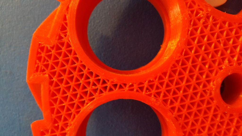
Below is a half-finished part that I hang on my wall to demonstrate some of the physical phenomena of 3D printing. I have referred to "layers thick" a few times already, and this is precisely what I am referring to, more correctly called "perimeters". Generally, the more perimeters you have around the outside of your part, the sturdier it will be. You can actually count the number of perimeters I have here, This one is 6 layers/perimeters thick. When I say "layers thick" this is what I mean, as opposed to "layers tall" or how many individual, horizontal layers make up your part (the number of cards stacked up in your deck).
The second quality to note is all the cross hatching hexitriangular nonsense you see in between the perimeters. This is called "infill" and basically allows for the print to be completed faster than if it was a completely solid part, and still keep the finished product relatively strong and lightweight. The infill basically forms many little "tubes" that follow the layers vertically upward, the view you see below is a "top" view, so the print bed was originally on the underside of this part. Not much to say here, except I like to keep my infill about 40%. This means 40% of the inside volume is occupied by the infill filament, and the remaining 60% is air. You can go anywhere from 0 to 100% infill, but at some point diminishing returns kicks in, and I supposed if you wanted to make a totally hollow part that's how you could do it.
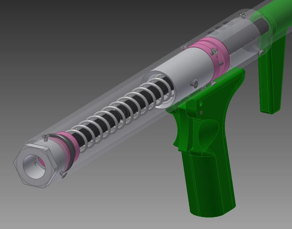
My Rostock is a delta style of printer, so these next parts may not look exactly like they do on other printers, but the principles and functions are identical. Below is a photo of the hot-end printing a part, now using green filament. The "hot end" is the general name for the entire assembly that heats up the solid plastic filament to a hot and sticky goo. That whole big thing. The nozzle is the tiny little brass thing at the very bottom making contact with that part that lays down the next layer. Those wires you see are hooked up to two heating resistors buried inside the hot end that heat the whole thing to 235 °C. If you've ever hooked up a resistor to a battery, you know it gets hot. Same idea here. All that orange cellophane looking stuff is actually a special heat resistant tape called Kapton. Keeps everything in place and doesn't melt until like 400 °C or something ridiculous like that.
2.2 Design of Parts
So you have your printer and now it’s time to design your own parts. This step is optional, if you just want to spit out pre-made parts there’s nothing wrong with that, but this is my hobby and I’ll cry if I want to. Good parts design is crucial to having printable components. I use Autodesk Inventor and save parts as their solid parts, as well as .stl, this seems to be the format that 3D printers like.
Remember that 3D printing is really just like stacking a deck of cards, one by one. Each card is only a few thousandths of an inch “tall”, but several inches long and wide. One card placed on a table is almost two dimensional. Stack 52 cards on top of each other, and look at that, you have a tangible 3D rectangular prism shape! Think of each card as a “layer” of the print; it may not be a rectangular shape, but you get the analogy.
Each layer is supported by the layer underneath it, or at least that’s what we are shooting for with parts design. I’m going to give you some examples of good and bad parts right here.
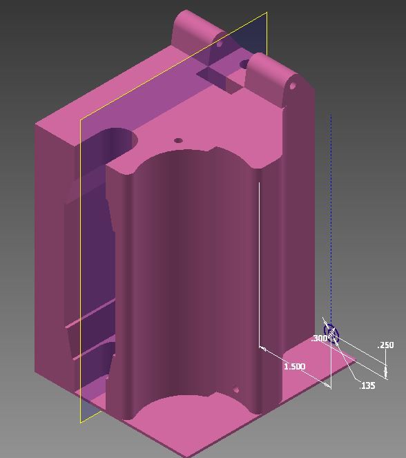
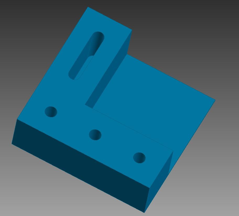
Let’s say I want to make this bracket shown below, measuring 3 inches tall, 3 inches wide, and only 1 inch deep. Is this a good orientation to print it? I.e. should the face currently on the bottom be what’s touching the hot bed?
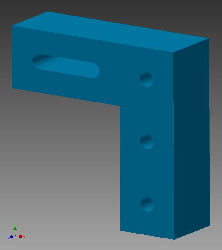
No. mostly certainly not. The Top-Left arm is not supported by anything underneath it. Remember the deck of cards analogy, now imagine each card is not rigid, but rather made of jelly. Each card is supported by the layer beneath it. With nothing to hold up that first layer of the bottom of the arm, the hot filament will fall right to the ground as it exits the hot-end. It doesn’t cure instantly, in fact the filament takes several seconds to fully cure/harden/cool. Like squirting elmers’ glue out of the bottle, it becomes a solid eventually, but it takes some time to get there first. Our “glue” dries faster, but it is still essentially a liquid when it’s squirted out, all the same. My rule is that every “arm” like this must have a lower face that is at least 25° away from horizontal. I think Kane’s rule is 45°, like I mentioned, everyone’s is different.
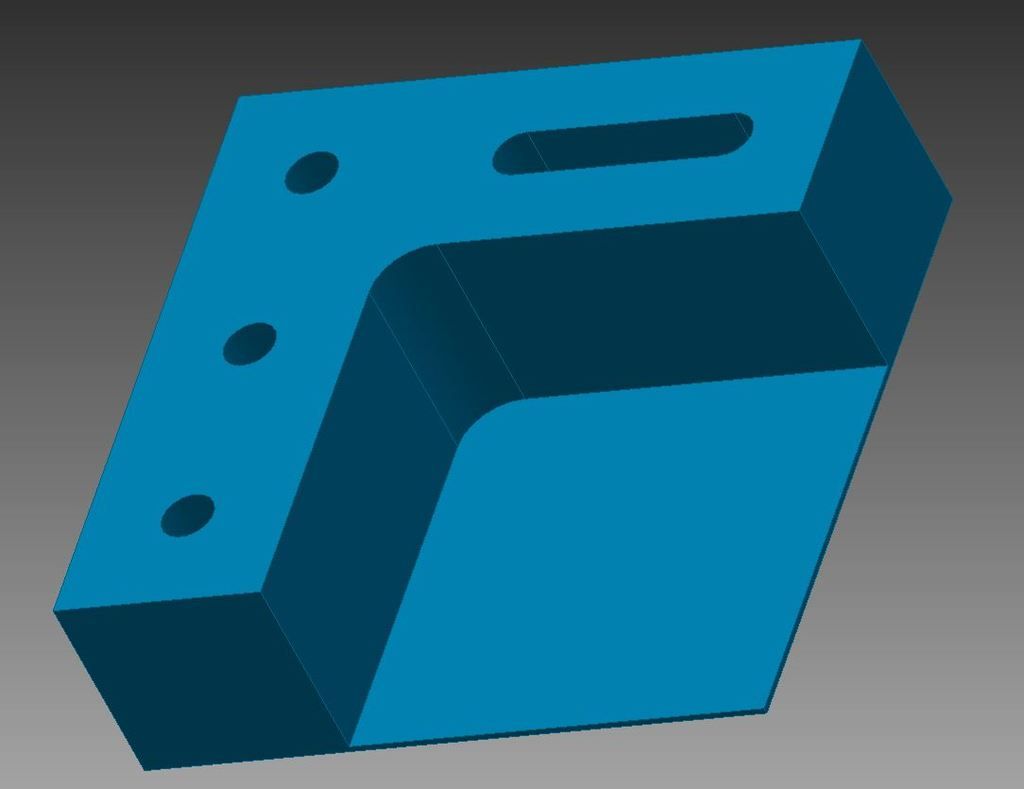
So we have two options here: Fix the part by applying the rule I mentioned above, or change the orientation of the part so another face is touching the hot bed. I will opt for the second one this time around…. So is this part “printable”?
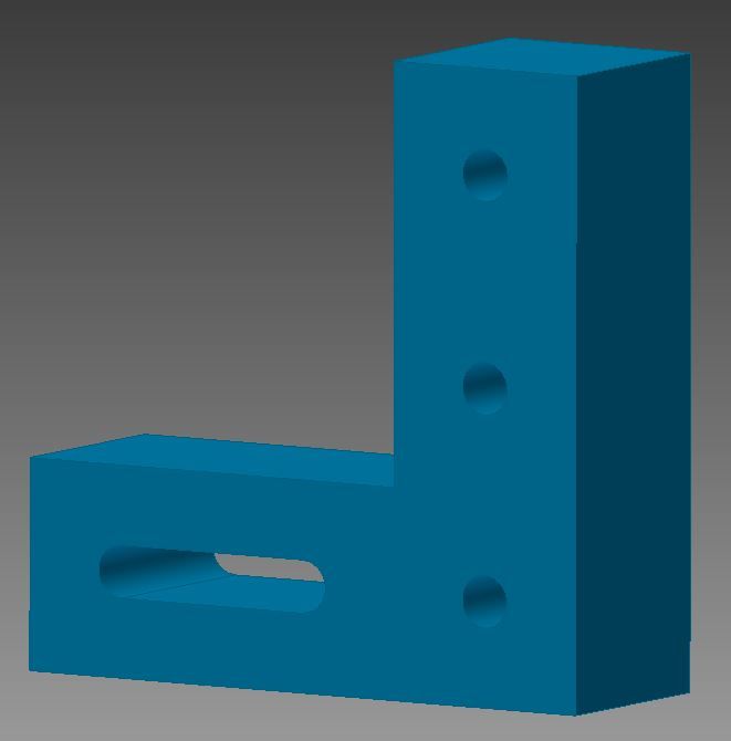
Hmmmm, I’d say it’s better but still not ideal. The channel on the bottom left part is left unsupported again, and will probably sag or produce a sloppy couple of layers. The circular holes shown typically aren’t as problematic because even though they are technically unsupported from directly below, they sort of build up to that point of being unsupported, and much like an arch bridge, provide enough support while it’s being printed to be not of major concern until the diameter exceeds maybe 2 or 3 inches.
So what do we do here? There are two options: Either change the orientation again or allow the use of support material on you printer software. I don’t like support material mainly because it seems to promote the use of poorly designed parts rather than making parts that are honestly better and stronger to begin with. Plus, it adds more steps to the end process of finishing off the parts, and leaves jagged or pointy bits that are uncomfortable and unsightly.
On this next orientation change, again we are left with some options. Either rotate the part again, so the channel is vertical, (which would work because it’s now essentially a circular hole on the top that will be supported well enough as previously mentioned,) or turn it on its’ side. This second option is probably the better one. Why? Well if each layer is only 0.2mm thick, the general rule is that it will always take longer to print vertically than horizontally. So if you can keep your parts short, keep your parts short. Let’s turn it on its’ side….
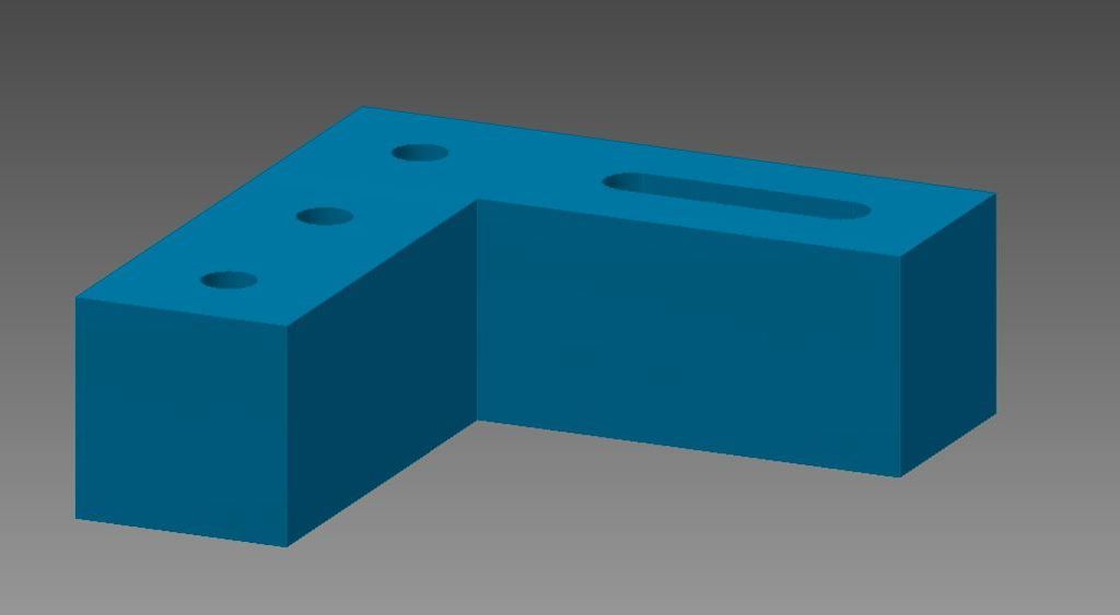
This is probably the best way to print this part, with one last little change I want to make. The first layer of your print is the most important, as a good bottom “bed” layer will ensure the best adhesion to the bed for the duration of the print. Small little details are not usually good for this, as they are likely to get knocked off during that crucial first layer of print. What I usually do for complex pieces is make a “raft” for the part that covers all the holes and smooths out the bottom face of the part. Below, all I’ve done is drawn a square bottom to the part and extruded it 0.030 inches, or about 4 layers. This is easy enough to remove with a knife or drill bit for the holes, and makes sure there is good contact with the hot bed. It adds some time to the print, but it helps with adhesion and therefore final quality in my experience. In short, the first layer of your print should always be kept SIMPLE. No holes, no weird wavy or jagged geometries. Keep it simple. A square, a circle, a rectangle.
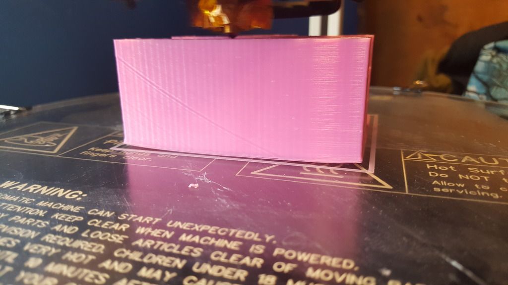
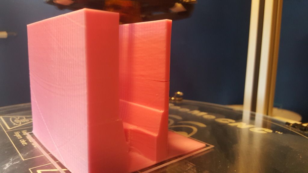
Another thing to keep in mind is the size of the part, or thicknesses of peninsulas on each layer. For example, the part shown below has a crack about midway up the far wall, because it is only about 1/4 inch thick at that point. Thin walls have the same tendency to curl up, but don't have the interlayer surface area to hold the top layer down like thicker layers. Something to keep in mind while designing, and just another reason 3D parts often look blocky or bulky. Also, a crack is visible on the close wall, right at the transition from angled to vertical where the magazine will eventually sit. This is due to a sharp angle transition, even one that small leads to a big stress concentration. This is why it's a good idea to make "prototype parts" first, that will print faster than the final part, and will reveal weaknesses in the design that may not have been apparent initially.
2.3 Principles of Engineering
Good parts design is essential to parts that aren’t going to fail in the field. I can tell you firsthand that just making the part a few layers thicker isn’t always going to solve your problems. The first generation of pullbacks were embarrassingly not up to the task of full on outdoor nerf wars. That being said, these failures have taught me a good deal about the weaknesses of 3D printing, and the amount of working around you will actually need to do to make a sturdy and robust part.
The first thing to remember is that these are literally individual layers that are sort-of-not-really adhered together. The filament extruding from the hot end never gets to a truly molten state, and rather just reaches a sort of glass transition temperature. The filament while being extruded gets squishy and sticky, but the layer beneath it is still fairly cool. A chemical bond is never actually formed between the layers, and the rule of thumb is that the 3D printed strength of an item is 30 percent that of an extruded/ injection molded part. Yeah. Less than a third of the strength. This is where people seem to have issue. 3D printing is not the golden goose egg to homemade blasters. Like a drill press, or a scroll saw, or a belt sander, it’s just another tool, and you don’t NEED any of them to make a banging Christina Hendricks (or Chris Hemworth, depending on your mood) homemade. Don’t forget that. You can’t just print anything you want willy-nilly. Go ahead, try to print a sentinel shell or something. It will literally fall apart. This is why the printed blaster parts we are familiar with are often thick or goofy looking. They NEED to be that way to even be a fraction the strength of their counterparts.
Morever, think of the stresses on the part. The interlayer surface planes will always be the weakest link in the part. Pulling apart the layers is pretty easy for example (tensile stress), but the parts handle COMPRESSION stresses very well. I’ve actually printed a set of longboard risers which are holding up with no problems because they are sandwiched between the metal trucks and the wooden deck, and are always in a state of compression. The PCSR catch shown below holds up well because the interlayer forces are largely compressive with a bit of shear. Reason out the stresses. Draw a free body diagram if you need to to visualize the forces. FEEL the stresses in your parts. An extra five minutes on paper will save you like seven hours on the print.
Think about the bearing stresses too. The force that occurs when a screw or bolt or rod is put through a hole in your part. It’s going to want to split your layers apart, whether pushing apart the layers like an axe, or prying them apart like a crow bar. Distribute these stresses wisely. Think 4 screws are good enough? Use 6 or 8. Be generous with your factor of safety. If your stresses are directly in line with tensile forces, there is a good chance that your part will be overstressed. If you have high stress components, either print the layers at an angle to the forces (to mix shear and tensile stresses) and ensure all your sharp corners are rounded out. Filet everything you can get away with. Sharp corners are particularly pronounced in 3D printed parts. Layers will almost always separate on a sharp transition. That first example we did REALLY should have a quarter inch filet on that inside corner….
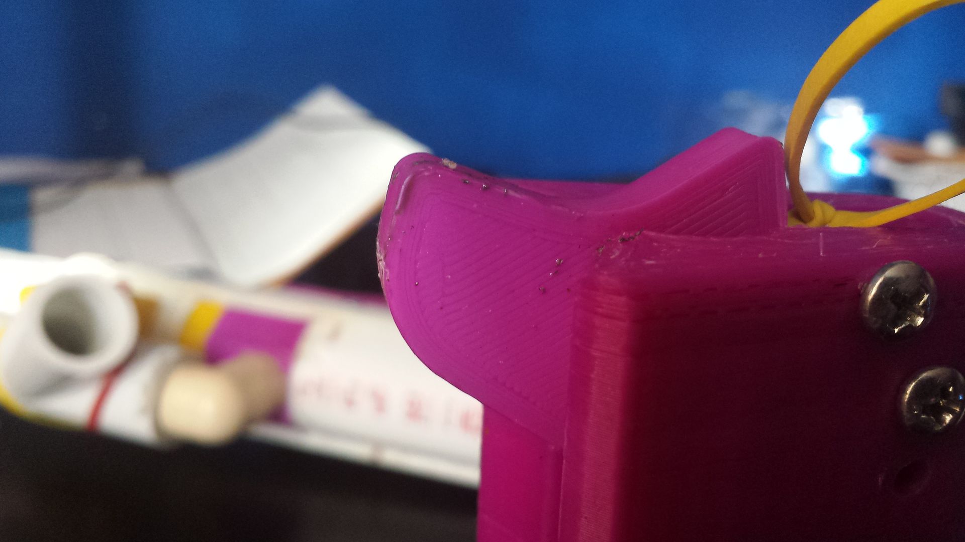
That’s better. Additionally, below is a comparison of the original pullback handles, with the mk V and up handles, with gradual filets on the inside corners, and a completely redesigned shape, with layers printed 8 degrees offset from the normal of the applied forces. Left is old, right is new.
3. PRINTER SETTINGS AND SUGGESTIONS
3.1 Technical Stuff
To reiterate, I use a Rostock Max V2 Delta style printer. My hotbed is borosilicate glass coated with 1-2 layers of purple glue stick glue, applied when the bed is cold. Wash this off with glass cleaner and replace with new glue every 6-8 prints, or whenever the ABS starts to peel from the bed. This hot bed is typically set at 108℃. Anything below this seems to peel off the bed too easily during printing. My hot end is a 0.5mm nozzle set to 235℃. Anything below 225℃ seems to result in delamination, or peeling, between individual layers, something that is highly unwanted in stress bearing components. EDITTED 9/26 for better results.
To combat delamination, I recommend the use of an enclosure. This can be as simple as a box made of wood or plastic, or a large storage container retrofitted with a small window and door. For enclosure heating, I have used incandescent light bulbs that I scrapped from an old desk lamp, and integrated these into the enclosure. There are certainly better heating options, but incandescent bulbs are cheap and can be found almost anywhere, and provide enough heat for my purposes. The enclosure doubles not only as a means of keeping heat in, but keeping the cold out. It suppresses the noise of the printer somewhat, and blocks the cool air of a fan or air conditioner or an open window which may provide inconsistent or accelerated cooling of your print layers.
I use Matter Control as my printing program. I print a MINIMUM of 8 layers thick on all components using the aforementioned 0.5mm nozzle, with an infill of 40%. For stress bearing components such as the Pullback under stock pull-bar, I use 10-12 layers thickness, and for rainbow catches, I print at 100 layers thick, to make sure that there is total fill on each layer. Speaking of, my layer height is 0.20mm. Smaller print layer heights have the problem of curling up on overhanging geometry, such as the back end of pistol grips, but once again, everyone’s experience is different. It’s always better to print a few more layers and wait a little longer, than rush the print job and have parts break on you in the middle of a war. Printing more layers will make your parts stronger, but if your part is poorly designed, it will merely be a bandaid on the problem.
For components with screw-holes, invest in a tap wrench with appropriate tapping bit. Tap the first ⅔ of the hole and let the screw tap the rest itself. This gives you a good adhesion to your part while preventing the part from splitting. If your part begins to delaminate or split, and you cannot be bothered to print another, I’ve found it best to apply some superglue or epoxy to the damaged area.
3.2 Community Input
Meaker suggests not to run PLA and ABS through the same nozzle or printer. This makes sense. If PLA melts roughly 150 °C lower than ABS, any ABS chunks left in a nozzle from previous prints would remain solid, and block up the printer.
Draconis recommends using ABS pipe weld to repair ABS parts. I've never tested this before but this really seems like a good idea. I just hope the results don't mimic those of acetone. Again, everybody has a different experience with this stuff, and I'm only here to point you in the right direction if I can.
3.3 Safety
You're working with really hot things. Should be obvious but don't touch the hot end or the bed. Even if you turned it off, it stays hot for a couple of minutes. Don't be an idiot.
Everything I have read suggests that 3D printing is overall safe. I understand tiny nanoparticles are produced, as well as a negligible amount of hydrogen cyanide. As it stands now, I largely ignore these issues, but you shouldn’t. A good idea is to print in a well ventilated area, in a relatively large room, windows open, that kind of thing. My eventual goal is to have several printers running in tandem in a large closet or enclosure with a proper ventilation system, ducts with fans directing air out of a window would not be something difficult to accomplish, and would be rather modular when I get my first apartment that would not take kindly to me tearing out walls. When I have a proper workshop, ventilation will be a real thing.
Fire safety is the real big deal. Google 3D printer fires and things get not-so-pretty. Again, my ideal long term setup is to have a simple Arduino controlled CO2 fire combat system within said enclosure to starve the fire. If you are not a mad scientist by the light of a full moon, there is another product for mortals to invest in that already exists on the market. I have yet to test it out, but it seems like a good idea. It’s called smoke signal; I’ve linked it at the end of this article, and I will make a review once I have it properly installed. It only shuts off printer power, and doesn’t actually put out a fire, but it does prevent the spread of an electrical fire. In conjunction with a CO2 flood from the aforementioned system, this could be a very effective tool in fire prevention.
All this being said, do not leave an active printer unattended! Always be within earshot of your printer, and if nothing else, stick a 5 dollar smoke alarm to the top of your printer! It may just save more than your new toy.
4. THE END
Have more to add? Leave a comment and I’ll add it in. If I ever receive a nooby 3D printer question I will respectfully refer you to this article to read in it's entirety. Think some advice is faulty or inconsistent with your own experiences? Write it in a comment. Think this article sucks? Roflcopter spend 6 hours of your weekend and write a better one. Anyway, thanks for the read and putting up with my dry humor.
Nerf on you beautiful technologists and engineers and tinkerers and athletes and artists. I hope this helps you in some small way.
-Aeromech
Additional Information Provided by:
Meaker
Draconis
Resources
ABS vs. PLA
http://www.protopara...r-3d-printing/]
ABS tips
https://www.matterha...inting-with-abs
Rostock Max 3D printer Instructions
http://download.seem...-2ndEdition.pdf
3D Printer Fire Prevention Device
https://3dprint.com/...-3d-print-fire/
#353088 PCSR: A new homemade design
Posted by
on 27 April 2016 - 12:10 PM
If I released the files as my own and claimed the design without crediting him at all, that would be rude.
Imports to both Cura and Sketchup come in as a few millimeters high. I'm thinking it's just a "convert to imperial" problem, but clarification would be ideal.
ED: Oh good gravy; I hope it's not the scale I think it's supposed to be. Some of these parts are *giant*. I'll need to modify them or they'll be too much material to risk on a very long (days) print.
Also: The scale appears to be way off.
I edited the READ ME FIRST file on the drive, I use imperial/freedom units when I build, so you may need to scale it up by 25.4. Interestingly, when I import to matter control, it defaults to mm, even though it's saved in inches, so I have to scale it back up anyway. Yes, the pistol grip is like 6 or 7 inches tall, the stock is about the same. They take a long time to print, but they feel pretty good. The longest print time on this was the stock at 14-18 hours? I can't recall which.
Also, your files are really cool and I like them, but good luck getting the ESLT style plunger seal to actually work. When I switched from O rings to the skirt seal my muzzle velocity easily increased by 30%. Since it's not as leaky as an ESLT it can better handle the improved seal.
EDIT: No it isn't rude, it's one more take on an amorphous solution to a problem with arbitrary design goals. Carry on, sir.
#353080 PCSR: A new homemade design
Posted by
on 26 April 2016 - 09:50 PM
Intentional necro to alert those interested of relevant information. Files are up. Instructions/complete parts list will be made available as the night rolls on
Linky linky --> https://drive.google...WG8tOGxPNHJ4WnM
#349640 Covering Operating Costs: Donations, Ads, Shirts, all of the above?
Posted by
on 24 November 2015 - 09:08 PM
If we had an actual store going that'd be dope. If shirts/wristbands were readily available, there may be more money to be made, as opposed to only buying stuff at APOC.
#347684 Do NOT Paint it Black
Posted by
on 05 July 2015 - 01:35 PM
Paint jobs have long been an integral part of cosmetic modifications of Nerf blasters, both homemade and modified stock blasters. It adds a level of individuality to a person’s blaster or company name if he/she wishes to market them. Legal and practical problems arise, however, when these paintjobs begin to resemble the color schemes of firearms, real or simulated. Metallic, rusted, black, flat dark earth, or military style camouflage paint colorations on nerf blasters are deleterious to the individual, the isolated nerf war, and the hobby as a whole.
Nerf blasters purchased from the store already resemble actual firearms, especially in silhouette, at a distance, or in low light. The Nerf Recon/Retaliator is one such blaster, and one of the most popular to modify into an imitation firearm, due to its’ close geometric resemblance to that of the military M4 carbine or popular civilian AR-15 carbine. The addition of an M16A2 carry handle or simulated carry handle on these toys contributes further to the outline of an actual weapon. Furthermore, tactical accoutrements such as slings, scopes, foregrips, and flashlights are not uncommon sights on todays’ Nerf blasters. These additions are largely innocuous, in that the underlying paint is still bright blue or orange or white, but do not help at distance or in low light conditions. Wars are often fought exclusively in the day, so this is not that big of an issue.
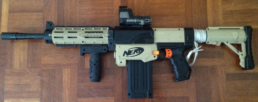
Figure 1: Nerf Retaliator modified to simulate M4 carbine [3]
The painting of one of these blasters is another story altogether. When the blues and greens and yellows are replaced with olive drab and desert brown and black, the appearance, as well as the law, swiftly changes on these blasters. What was clearly a toy can now be mistaken for a real steel firearm, even at relatively close distances. The same could be said of homemade blasters, which often can be mistaken for improvised firearms by jumpy bystanders with no knowledge of firearms or the strengths of common materials.
But U.S. federal regulations dictate that as long as the orange tip is preserved, the blaster is totally fine in the eyes of the law so long as certain markings are maintained, such as this one:
So the argument can be made that if the orange tip is preserved, the blaster still falls within legal ground. While this may be true, the spirit of the game, and the perception of it to others changes dramatically. If brightly colored blasters or PVC homemade blasters are left in their original colors, or painted flamboyantly, a passerby to one of our wars will clearly see that these blasters do not pose a threat, and that the players are not looking to intimidate. Now if these blasters are painted black or desert brown, and a bystander sees one or more of these, there is an air of discomfort. To the ignorant, our harmless games begin to resemble para military exercises. Even if legal to the letter of the law, there is nothing stopping a bystander from calling the police, and having the players kicked out of the public playing area under some fabricated charge.
This is a major advantage that Nerf has to airsoft and paintball. The game can be played in a public park, without the investment of expensive equipment or specialized game fields. Even if the game itself is not to be regulated on a federal level, if local parks are made hostile to the wars that are often held there, we would need to relocate. It only takes one arrogant player to talk back to a passerby or one errant dart to hit a passing child to have us vilified. The culture of our game is dependent on the passivity of outsiders, and, as seen in broadcast media, our reputation has nowhere to go but down. If one catastrophe was to take place, our game may very well be regulated, and we don’t need to add any fuel to the fire by painting our blasters black.
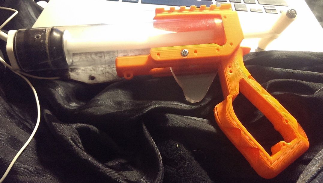
Figure 2: Homemade Nerf pistol with clear plunger tube, and bright color [4]
Imagine if every game was required to be played in an airsoft arena. Months worth of notice would need to be given to arenas, and their schedule worked around. Every game would warrant additional payment to these fields or arenas on top of travel and potential lodging costs for those of us that drive long distances to Nerf. The spontaneous weekend war would cease to exist, and the few large scale wars we do have would be nearly impossible.
The moral of this article is to keep your blasters their stock colors, or paint them, “white, bright red, bright orange, bright yellow, bright green, bright blue, bright pink, or bright purple” [1]; keep them looking like toys. Let’s continue to be those geeks at the park with those weird toys, and not earn ourselves the reputation of troublemakers. Stay safe, stay smart, and Nerf on.
Disclaimer: I am not a lawyer, nor do I profess to have an expertise in the law in any way. I am in no way responsible for your actions. Please consult a lawyer before undertaking such endeavors. This article focuses on United States Federal Law, but the spirit of the argument may be extended to all principalities. For those in the U.S. I recommend glancing through the referenced material, particularly the first.
References:
[1] “Part 272-Marking of Toy, Look-Alike and Imitation Firearms.” Electronic Code of Federal Regulations. 23 Jan 2013. U.S. Government Publishing Office. Web. 2 Jul 2015.
[2] “Penalties for entering into commerce of imitation firearms.” Legal Information Institute. 5 Nov 1988. Cornell University Law School. Web. 4 Jul 2015.
[3] srsim2. "Nerf Paintjobs." deviantart. Web. 5 Jul 2015.
[4] Lucian. "Homemades Picture Thread." Nerfhaven. 27 Oct 2013. IP.Board. Web. 5 Jul 2015.
Nerf blasters purchased from the store already resemble actual firearms, especially in silhouette, at a distance, or in low light. The Nerf Recon/Retaliator is one such blaster, and one of the most popular to modify into an imitation firearm, due to its’ close geometric resemblance to that of the military M4 carbine or popular civilian AR-15 carbine. The addition of an M16A2 carry handle or simulated carry handle on these toys contributes further to the outline of an actual weapon. Furthermore, tactical accoutrements such as slings, scopes, foregrips, and flashlights are not uncommon sights on todays’ Nerf blasters. These additions are largely innocuous, in that the underlying paint is still bright blue or orange or white, but do not help at distance or in low light conditions. Wars are often fought exclusively in the day, so this is not that big of an issue.

Figure 1: Nerf Retaliator modified to simulate M4 carbine [3]
The painting of one of these blasters is another story altogether. When the blues and greens and yellows are replaced with olive drab and desert brown and black, the appearance, as well as the law, swiftly changes on these blasters. What was clearly a toy can now be mistaken for a real steel firearm, even at relatively close distances. The same could be said of homemade blasters, which often can be mistaken for improvised firearms by jumpy bystanders with no knowledge of firearms or the strengths of common materials.
But U.S. federal regulations dictate that as long as the orange tip is preserved, the blaster is totally fine in the eyes of the law so long as certain markings are maintained, such as this one:
A blaze orange (Fed-Std-595B 12199) or orange color brighter than that specified by the Federal Standard color number, marking permanently affixed to the exterior surface of the barrel, covering the circumference of the barrel from the muzzle end for a depth of at least 6 millimeters.
So the argument can be made that if the orange tip is preserved, the blaster still falls within legal ground. While this may be true, the spirit of the game, and the perception of it to others changes dramatically. If brightly colored blasters or PVC homemade blasters are left in their original colors, or painted flamboyantly, a passerby to one of our wars will clearly see that these blasters do not pose a threat, and that the players are not looking to intimidate. Now if these blasters are painted black or desert brown, and a bystander sees one or more of these, there is an air of discomfort. To the ignorant, our harmless games begin to resemble para military exercises. Even if legal to the letter of the law, there is nothing stopping a bystander from calling the police, and having the players kicked out of the public playing area under some fabricated charge.
This is a major advantage that Nerf has to airsoft and paintball. The game can be played in a public park, without the investment of expensive equipment or specialized game fields. Even if the game itself is not to be regulated on a federal level, if local parks are made hostile to the wars that are often held there, we would need to relocate. It only takes one arrogant player to talk back to a passerby or one errant dart to hit a passing child to have us vilified. The culture of our game is dependent on the passivity of outsiders, and, as seen in broadcast media, our reputation has nowhere to go but down. If one catastrophe was to take place, our game may very well be regulated, and we don’t need to add any fuel to the fire by painting our blasters black.

Figure 2: Homemade Nerf pistol with clear plunger tube, and bright color [4]
Imagine if every game was required to be played in an airsoft arena. Months worth of notice would need to be given to arenas, and their schedule worked around. Every game would warrant additional payment to these fields or arenas on top of travel and potential lodging costs for those of us that drive long distances to Nerf. The spontaneous weekend war would cease to exist, and the few large scale wars we do have would be nearly impossible.
The moral of this article is to keep your blasters their stock colors, or paint them, “white, bright red, bright orange, bright yellow, bright green, bright blue, bright pink, or bright purple” [1]; keep them looking like toys. Let’s continue to be those geeks at the park with those weird toys, and not earn ourselves the reputation of troublemakers. Stay safe, stay smart, and Nerf on.
Disclaimer: I am not a lawyer, nor do I profess to have an expertise in the law in any way. I am in no way responsible for your actions. Please consult a lawyer before undertaking such endeavors. This article focuses on United States Federal Law, but the spirit of the argument may be extended to all principalities. For those in the U.S. I recommend glancing through the referenced material, particularly the first.
References:
[1] “Part 272-Marking of Toy, Look-Alike and Imitation Firearms.” Electronic Code of Federal Regulations. 23 Jan 2013. U.S. Government Publishing Office. Web. 2 Jul 2015.
[2] “Penalties for entering into commerce of imitation firearms.” Legal Information Institute. 5 Nov 1988. Cornell University Law School. Web. 4 Jul 2015.
[3] srsim2. "Nerf Paintjobs." deviantart. Web. 5 Jul 2015.
[4] Lucian. "Homemades Picture Thread." Nerfhaven. 27 Oct 2013. IP.Board. Web. 5 Jul 2015.
#346458 How to deal with people
Posted by
on 28 April 2015 - 01:54 PM
How to plan and host a nerf war.
Typically, the shooter calls the hit, and if it's questionable, just take the hit. Last war, I got "hit" in my (poofy) hair and while technically not a hit, I took myself out because it's easier than arguing and makes the rest of the game go smoothly. It's a game so don't make a big deal out of it especially if you're going to be running around again in <5 minutes. Don't be the person to ruin the game for everybody else.
Typically, the shooter calls the hit, and if it's questionable, just take the hit. Last war, I got "hit" in my (poofy) hair and while technically not a hit, I took myself out because it's easier than arguing and makes the rest of the game go smoothly. It's a game so don't make a big deal out of it especially if you're going to be running around again in <5 minutes. Don't be the person to ruin the game for everybody else.
#345770 [PA] Nerf War at Plains Airsoft Arena, Sunday March 22nd
Posted by
on 24 March 2015 - 11:41 AM
I guess we're doing the pros-cons thing?
Pros:
Two story castle defense
Killer cast of nerefers, meeting new people and some old ones from wars past
Getting featured on griever's YouTube channel
Seeing new designs from Drev and the Unholy 3
Teamwork
Being able to rush through ample cover
Zorn getting some Effeminate action shots
People using my blasters and experiencing them Aeromech ergonomics
Just good sportsmanship among all participants
Cons:
Dem 4Bs
Good job Koree
#343998 Reverse Wye Hopper
Posted by
on 07 January 2015 - 02:03 AM
So I have received more than a few requests to explain how my reverse wye hopper works, and yes, it does work.
This is a Drev Bullpup with a reverse wye chopper, and one that started the inquisition. I'm using a chopper because I wanted to keep this as compact as possible, but a hopper without the 45 degree coupler would actually work better, because you don't have to change position to load a new dart into the chamber.
This image, posted by Gears was the one that actually inspired the above blaster, a bullpup with a horizontal top feeding magazine. It keeps everything compact and I wanted to give it a shot.
Here's the full assembly. Darts are loaded with the heads facing upwards. When the blaster is primed, the suction from the skirt seal actually pulls the dart backwards into the stub; the screw in the stub prevents the dart from being sucked into the air supply source. The dart is now seated and the head should have fallen away from the clip. The dart is now in line with the barrel. When the blaster is fired, the dart is forced out through the barrel.
And here's the detail view.
(1) Marks the area that needs to be filed down with a rat tail file, just get it in there and start removing material. It will feel new and strange at first, but you'll learn to enjoy it.
(2) Denotes the part of the stub that must be chamfered smooth. Just like the barrel, a bevel is necessary to allow the darts to feed smoothly backwards into the stub. Just do this like you would do it on the barrel throat.
(3) The screw that prevents the darts from being sucking into the air supply chamber
Notes
This has not been war tested, but it seems to work pretty well. Keep in mind my darts are slightly shorter than the standard, I usually rock about 1-1/8 inch long darts. Don't ask me how I arrived at that figure. If your darts are longer than that, just adjust the distance of the screw from the throat of the stub until you get reliable feeding. This sort of solves a problem that doesn't exist, but I hope it may be useful to some of y'all out there.
She likes showing off.

This is a Drev Bullpup with a reverse wye chopper, and one that started the inquisition. I'm using a chopper because I wanted to keep this as compact as possible, but a hopper without the 45 degree coupler would actually work better, because you don't have to change position to load a new dart into the chamber.

This image, posted by Gears was the one that actually inspired the above blaster, a bullpup with a horizontal top feeding magazine. It keeps everything compact and I wanted to give it a shot.

Here's the full assembly. Darts are loaded with the heads facing upwards. When the blaster is primed, the suction from the skirt seal actually pulls the dart backwards into the stub; the screw in the stub prevents the dart from being sucked into the air supply source. The dart is now seated and the head should have fallen away from the clip. The dart is now in line with the barrel. When the blaster is fired, the dart is forced out through the barrel.

And here's the detail view.
(1) Marks the area that needs to be filed down with a rat tail file, just get it in there and start removing material. It will feel new and strange at first, but you'll learn to enjoy it.
(2) Denotes the part of the stub that must be chamfered smooth. Just like the barrel, a bevel is necessary to allow the darts to feed smoothly backwards into the stub. Just do this like you would do it on the barrel throat.
(3) The screw that prevents the darts from being sucking into the air supply chamber
Notes
This has not been war tested, but it seems to work pretty well. Keep in mind my darts are slightly shorter than the standard, I usually rock about 1-1/8 inch long darts. Don't ask me how I arrived at that figure. If your darts are longer than that, just adjust the distance of the screw from the throat of the stub until you get reliable feeding. This sort of solves a problem that doesn't exist, but I hope it may be useful to some of y'all out there.

She likes showing off.
#343369 Enclosed Slotless Pump Snap
Posted by
on 08 December 2014 - 01:11 AM
Preface
Wanted to try my hand at making a venerable snap style blaster that was just different than everything I've seen before. This design uses elements from my experiences with rainbows, as well as some other inspiration form real life blasters. After experimenting with some snap building techniques in past blasters, I decided on my design goals and set out.
Last time on New Girl
Carbon creates the SNAP blaster and dozens of variants and interpretations follow
Meaker creates the SNAP 8 in an incredibly detailed writeup. Read it if you want to build a SNAP, a good chunk of this is based on his writeup.
I create a Rainbow with Snap elements.
Goals
Create an enclosed design, whereas the plunger rod is never exposed to the user's face or fingers.
Use only hardware store parts, (save the [k26] spring.)
Minimize the use of special tools.
Weight must be equal to or less than one of my rainbow pumps.
Handle must be comfortable in the hand.
Length of pull must be equal to or less than that on one of my rainbow pumps.
In this writeup, descriptions are underneath the referenced image.
After things settle down I'll put up a complete parts list.
Plunger Assy.
Simple superlative plunger head. I changed it up a little using a 10-32 x 1/2" screw with a stop nut, or nylon nut, to prevent the nut from shaking loose, and a #10 flat washer. Seems to work OK. Just Don't overtighten it. Otherwise it might fall apart on you.
Screw that onto some CPVC with a x6 metal screw.
Measure 3-5/8" from the end of the CPVC endcap and mark it on the CPVC pipe. Drill a 1/4" hole into one wall of the pipe.
Internal Bushing
A note on bushings:
There are several types of bushings out there, The two on the right are found at Ace Hardware, and the one on the left is found at Lowes. The important thing here is to have a tight fit with 1/2" PVC pipe.
Jam some 1/2" PVC into the bushing. Make sure it's in there solid. You can use superglue if you want, but you really don't need to.
Cut off the head of the bushing with the 1/2" PVC still attached.
Next, use the rat tail file to ream out the hole in the PVC pipe...
...so that 1/2" CPVC will fit through without any resistance.
The spring will eventually rest against this part, which is why superglue is not necessary; there will always be a force on the PVC pipe to keep it in place.
Wrap some E-tape around the internal bushing we just created, as well as around another, stock bushing, to act as the front bushing. For the internal bushing, the tape should allow for a snug fit of the part inside 1-1/4" PVC, but not so tight that it cannot be moved around inside this 1-1/4" PVC (body tube).
Body Tube
The Body tube is a length of 1-1/4" PVC x 18.5" long. The above photo shows a simple method to arrive at near perfect 120 degree angles around the tube. Use the already perfect hexagon on the bushing to mark out 1/3 of the circle of the body tube. This template will allow the builder to approximate where to sink screws, when three are required to affix a part.
Insert the bushing into the back of the 1-1/4" PVC pipe with the flat part of the bushing (the face we just cut) facing forward.
Position the bushing so the front face is 12-1/8" from the front of the 1-1/4" PVC Pipe, the body tube.
With the bushing positioned as described above, measure 12-3/4" from the front of the body tube, and make a mark, Use a 1/8" drill bit to drill through this point, and sink in a 6-32 x 1/2" flat head machine screw. Don't countersink it yet, this is just to pin the bushing in place.
Wrap a piece of masking tape around the body tube with one side of the tape aligned with the screw. This allows the "longitude" of the next two hole to be determined. Use the markings on the front of the body tube created with the reference hexagon bushing to approximate the "latitude" of the holes. In short, three evenly spaced hole should exist at an equal distance from the front face of the body tube.
Drill and countersink the remaining two screws. Then remove and countersink the first hole, and replace the screw. The heads of the screws should be flush with the body tube outer surface.
Internal shot from the rear.
The Trigger
On the bottom of the body tube, (the convention being the writing-side,) mark a spot evenly between the ring of screws made in the previous step.
Nothing new here for snap builders. Saw off the legs of the clothespin, leaving the fingers intact. Mark a spot on the center of one of these fingers.
Line up the two points marked...
And secure the clothespin half so these points line up, using one 6-32 machine screw.
Add another one just for good measure. As you can see I'm following the cut out portions of the clothespin. This one I did need to countersink.
Here we are. Cut down your nail so it's about 1-1/8" long from the bottom surface of the head to the tip. Round it off with sandpaper. Be sure not to create too much heat if you use a rotary too or belt sander, the heat will increase the hardness of the steel if it gets too hot, which is not desired. The CPVC is already soft, so making the steel nail harder will only increase the rate of wear. Take your time on the nail.
Here is a cut down 6-32 machine screw. It is now only 3/8" or so long. I used a dremel and pliers. A hacksaw and vice would work just as well.
My Lower trigger unit. Used some E-tape to prevent rotation about the single screw holding the L-bracket in place.
Assemble the two trigger halves. Drill a 1/8" hole through the two fingers of the trigger assy, as well as the body tube.
Remove the lower trigger unit and ream out the hole shown in the above diagram just a bit, the objective is to have the nail move freely in and out of this hole.
Next re-assemble the trigger and give it a few squeezes. Drill a speed hole 1-1/2 to 2 inches ahead of the trigger. I chewed into my bushing in this photo. but it really doesn't matter.
The Pump
Cut out a 1" length of 1-1/4" PVC
Wrap the segment in E-tape and throw it into the end of your 1-1/2" thinwall PVC. Make the faces flush.
Secure it in place with three screws. I ended up using three 6-32 machine screws cut down to 3/8"
Next mark out a shallow "V" shape extending from the top to one side to the bottom. The valley of the "V" should extend about 1/2 - 5/8" deep. Repeat on the other side.
Use a hacksaw to cut away the V shapes that were previously formed. This is what makes the design "slotless." When the plunger rod is pushed back by the pump, the CPVC Tee rests in the crotches of the V channel at the end of the pump, orienting it exactly as desired.
Another view.
Draw a 16" Long x 7/8" wide rectangle on the bottom of the pump from the rear.
Drill 1/4" holes so that the formed holes are tangent to the sides of the rectangle...
And saw all the way down each length of the rectangle. Remove the rectangle from the pump. Then remove the inner section of 1" PVC that was cut through. It will be replaced later.
OK technically this is a slot. But no dremel is needed. And a long, straight saw means long, straight cuts. I avoid using rotary tools whenever possible.
Handle
I used a Hole saw and a Wood saw to create this part from a 3/4" x 5" wooden plank. It's about 2 feet in length. The width from top face of the rear "panhandle" to the bottom face is one inch.
Drill three holes 1 inch apart on the top of the Body tube, and position these holes so the trigger is the desired distance from the front of the handle. Drill a 1/8" hole into the handle from the top, and sink in a wood screw, 1" long, into the front hole.
Make sure it's straight. This is important. The two parts are only held together by one screw, so rotation is possible. Pre-drill and sink in the remaining two screws when it's aligned.
Cut out 1/8" from the top face of the panhandle and continue this cut all the way to the end. This allows a piece of 2 inch PVC to align cocentric with the body tube. Don't have a better photo of this, sorry.
Putting it Together
Slide on the Pump from the front. Re-attach the piece of 1-1/4" PVC to lock the pump onto the blaster.
Throw the plunger assembly into the blaster through the front.
Throw in the forward bushing. It should rest in very snugly. Remove a layer of tape if it is too tight to fit. Drill and countersink three holes and sink three screws. Use a 7/64" drill bit and 6-32 x1/2" machine screws. Ensure they are flush.
Cut off the excess CPVC plunger rod. Leave about an inch sticking out from the pump.
Prime the blaster by sticking a length of 1/2" CPVC through the front of the blaster and pushing it back all the way. Rotate the rod in this position until it the catch locks. Take note of the orientation of the rod and the pump crotch.
Affix the CPVC Tee onto the end of the plunger rod to using a x6 x 1/2" machine screw once it is positioned.
Mark some points on the rear of the stock, about 2 inches apart. I made three points. Drill through these points with a 1/8" drill bit.
Position the 2" PVC pump sheath over on the rear of the stock. Drill x3 1/2" holes on the top that align with the three holes in the stock.
Affix the Pump sheath to the blaster, and secure with wood screws. Make sure the 2" PVC pump sheath is positioned so the pump may be pumped back fully. Drill through the holes in the stock, through the PVC, from the bottom. Drill the front most hole first, and sink this screw from the top. This allows the sheath to be rotated if need be. Then sink the remaining two screws when satisfied with the positioning.
Finishing Touches
Cut down the front of the pump.
Saw off the excess material from the rear. Like take a hacksaw and just cut through the entire end of the blaster, so only about an inch remains between the CPVC Tee and the rear face of the pump sheath.
File down the handle and then finish with fine grit sandpaper.
Use the rat tail file for the internal angles.
I finished the stock with Boiled Linseed Oil for a more natural fee, and to seal the wood of course.
Install some side plates to make your handle suck less. Mine are too wide, but I can easily trim them down. It's just cutting board after all.
Trace around your handle.
Cut out the basic shape.
Use a file, knife, and snadpaper to round out the edges. I went for simple 1911 style grips. I do need to file them thinner in the future, but I'm too lazy to do so right now.
Screw 'em on.
You knew that was coming.
Results
With a 14" barrel and hopper, the blaster is 45" long, about 3" longer than one of my rainbow pumps. The RBP in the photo is sporting a 12" barrel, so it would be a little longer if the barrels were equal length.
Range is untested, but it hits with just slightly less force than a rainbow pump. It is totally war capable in terms of ranges alone. I have yet to field it but I look forward to the challenge. The length of pull is identical to my rainbow pump, which is already pretty long. I wouldn't want it any longer to be honest, and prefer a shorter stock. The blaster this is loosely inspired by is Langly's Pump-Snap. However, I am not nearly as tall as he is, so the sheath was necessary to make that length of pull manageable, otherwise more stock would be needed to allow my face to rest behind the plunger rod. Weight is about the same as a rainbow pump, perhaps a little lighter.
This was kind of cool. I don't typically work with Snaps so this was a nice change of pace. That being said, the project was completed in a day once I had the materials available, all from my local Ace hardware with the exception of the [k26] spring, which is easily available these days, and the thinwall PVC, which I found online and is apparently everywhere except long island. I hope this helps with anyone that wants to build a pump snap. As always, look around and see which blaster design is the best for you. This is the second actual Snap I've built, and the first one wasn't too hot. I set out with a list of goals and accomplished them. I will be using this at the next Northeast war. And if it breaks, you'll know.
Just don't go calling me a Snap guy
-Aeromech
#341301 Voltage Increase In Vulcan
Posted by
on 18 August 2014 - 08:52 PM
What do you mean by "Winter" temperatures? I live in an area where it gets down to -22f (-30C).
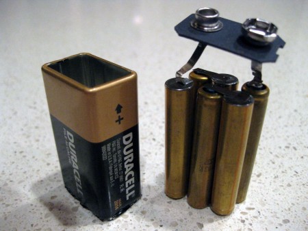
I mean I've accidentally left a blaster in my car in the middle of HVZ week and needed to change the batteries to get the thing working again. A battery functions because of a chemical reaction that produces a flow of electrons. Cool down that reaction and you also slow it down, yielding a lower power output. If you crack open a 9V battery it's really just 6 tiny cylinder batteries stacked together like this. They are extremely susceptible to this phenomena because the individual battery piles are so small.
I have a problem however where it fails to load the belt and keeps turning over without the chain cogs grabbing. I end up needing to help feed it through. Is this a problem with the multi-level gear being improperly aligned?
From my experience this is more of a design flaw. The spring on the multi-level co-centric gear is aligned just fine. This is a safety feature designed to allow the operator of the blaster to pull a chain through without damaging the gears. Open up the blaster and notice a set of teeth that grab each other, but not incredibly tightly. These gears are design to pull apart enough to "slip" when enough force is applied; this occurs when the chain is pull through or when it's advance is prohibited. This is a really poor design because I have had Vulcans have many feeding issues similar to what you describe. See if you can put a stronger spring in that section, but if I recall these gears are stupid small, like 1/2" diameter tops, and you have to dissect your blaster fairly far to get to it. The other option is to fuse the two parts of the slip-gear together, but in the (likely) event of a jam, trying to pull the chain through would wreck your internals. Unless you modded the chain door to have a manual release a la airzone punisher.
Long story short, your problems are related to the Vulcan being flawed, not really anything you did wrong.

