Jump to content


Photo

Abp5k

Actuated Breech Pistol II

160 replies to this topic

#1 CaptainSlug

CaptainSlug

    Resident Mad Scientist

  • Administrators
  • 4,763 posts

Posted 11 September 2007 - 08:14 PM

So the old thread was getting too cluttered. That and the design has changed great deal since the concept was first proposed. The functional goal is still the same, only the approach and parts are very different.

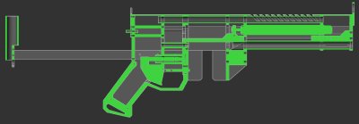
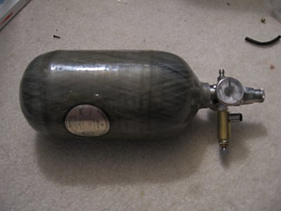
Aim: To make a fully semi-automatic magazine-fed Nerf weapon. One trigger pull fires one dart, and the cycle is self operating with no operator input aside from the trigger. Gun is powered from a pressurized external tank and operates at 30-40psi.

The mechanism is as follows.
Posted Image
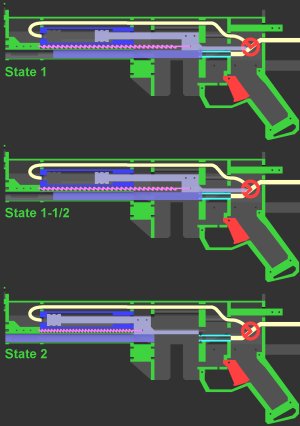
State 1: Trigger neutral. Supply input pressurizes air cylinder (breech actuator)

State 1-1/2: Trigger is held down. This inbetween state only lasts around half of a second. The directional control valve connects the air cylinder to the output and closes off the tank supply line.
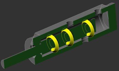
The barrel is sealed against the output while the air cylinder is depressurizing into the barrel to exhaust to atmosphere (and thusly shoot the dart).

State 2: Trigger is still held down. Air cylinder has completely depressurized and weak spring return can now overcome the pressure level of the air cylinder in order to return it to the forward position and open the breech.

Cycle returns to State 1 when the trigger is released. Time duration of State 1-1/2" is dependent upon the load added with the spring return. Hence the decision to use an extension type spring which is easier to adjust. The return spring really only needs to overcome the friction of the o-rings.

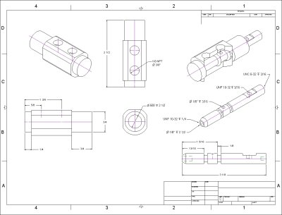
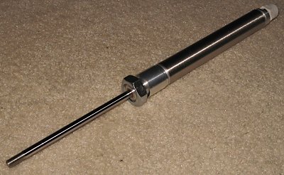
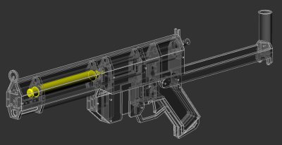
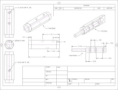
I realized that the air cylinder did not have to be made custom because a wide range of bore sizes are available, so based on some very easy math I figured out what size I needed, and altered the CAD model to accommodate the off-the-shelf part.
Posted Image
Posted Image
Tomorrow I will do the lathe work on the high flow rate directional control trigger valve.
Posted Image
Posted Image
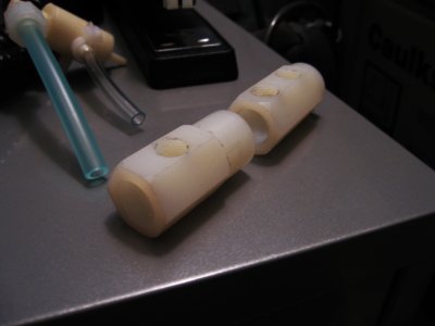
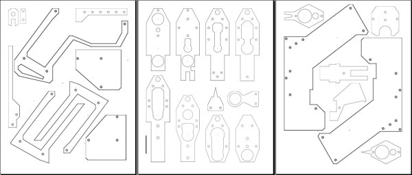
And this weekend I will start on cutting all of the raw materials to size and applying the templates I have made from the CAD model.
Posted Image

Edited by CaptainSlug, 11 September 2007 - 08:16 PM.

  • 0
The little critters of nature, they don't know that they're ugly. That's very funny, a fly marrying a bumble bee. I told you I'd shoot, but you didn't believe me. Why didn't you believe me?

#2 Nonsense Man

Nonsense Man

    Member

  • Members
  • 308 posts

Posted 11 September 2007 - 08:32 PM

Well I think it looks awesome.Also your using the tank you made for your magstrike right or are you making some awesome miniature version that is located on the back of the gun (kind of like the design of a paintball gun) because that would be awesome.
  • 0
QUOTE(1lastnerfgun @ Apr 19 2008, 08:39 AM) View Post

40 shots for 40 cocks


#3 CaptainSlug

CaptainSlug

    Resident Mad Scientist

  • Administrators
  • 4,763 posts

Posted 11 September 2007 - 08:58 PM

I will be using either the Low Pressure tank I made for the Magstrike, or the adjustable 88/4500 HPA tank (once I get the regulator on it rebuilt).
  • 0
The little critters of nature, they don't know that they're ugly. That's very funny, a fly marrying a bumble bee. I told you I'd shoot, but you didn't believe me. Why didn't you believe me?

#4 Nonsense Man

Nonsense Man

    Member

  • Members
  • 308 posts

Posted 11 September 2007 - 10:36 PM

But do you think it would be possible to do something like that?
  • 0
QUOTE(1lastnerfgun @ Apr 19 2008, 08:39 AM) View Post

40 shots for 40 cocks


#5 CaptainSlug

CaptainSlug

    Resident Mad Scientist

  • Administrators
  • 4,763 posts

Posted 11 September 2007 - 10:56 PM

But do you think it would be possible to do something like that?

Yes it's possible. But I will be keeping the tank in a backpack and running low pressure line to the gun. I'd rather not have a tank droplined on the bottom of the grip.

Edited by CaptainSlug, 11 September 2007 - 10:57 PM.

  • 0
The little critters of nature, they don't know that they're ugly. That's very funny, a fly marrying a bumble bee. I told you I'd shoot, but you didn't believe me. Why didn't you believe me?

#6 KBarker

KBarker

    Member

  • Members
  • 131 posts

Posted 12 September 2007 - 03:11 AM

If you're lazy and have a lot of extra cash, you could have all those parts waterjet cut out.
  • 0
-KBarker

My Fighting Robots: http://www.TeamVelocityRobotics.com/

#7 KBarker

KBarker

    Member

  • Members
  • 131 posts

Posted 12 September 2007 - 03:12 AM

Shit, sorry.

Edited by KBarker, 12 September 2007 - 02:09 PM.

  • 0
-KBarker

My Fighting Robots: http://www.TeamVelocityRobotics.com/

#8 Galorn

Galorn

    Member

  • Members
  • 56 posts

Posted 12 September 2007 - 04:53 AM

That looks really cool. I wonder how hard it'll sling darts.
  • 0
My heatware info;

Username: Galorn
Email: Galorn2@aol.com


#9 General Cole

General Cole

    Member

  • Banned
  • 868 posts

Posted 12 September 2007 - 05:12 AM

Well by looking at the pressure chamber (plunger tube) it looks like it will hit 60s. Is it still LS mags? Or have the mags been rebuilt?
We should stop calling out/making fun of/pissing GC off. He's actually contributed and is available for trade. He's a better than average member no doubt. Got your back Cole.
-Nerfer34

You know what... I know it's kinda late... but Props Cole.
-Baghead

#10 CaptainSlug

CaptainSlug

    Resident Mad Scientist

  • Administrators
  • 4,763 posts

Posted 12 September 2007 - 08:03 AM

Considering the volume and pressure involved, this gun should be able to hit atleast 80 feet. but we'll find out in a week or two.

If you're lazy and have a lot of extra cash, you could have all those parts waterjet cut out.

I would only consider having them laser or water-jet cut if I were to make these in bulk, or if I had no free time. I don't think the parts are complicated enough to warrant it.

Well by looking at the pressure chamber (plunger tube) it looks like it will hit 60s. Is it still LS mags? Or have the mags been rebuilt?

It will use LS mags to save time and effort. Making them from scratch would be too annoying.

Edit: Lathe work on the valve is done. I just need to make the valve rod.

Edited by CaptainSlug, 12 September 2007 - 01:15 PM.

  • 0
The little critters of nature, they don't know that they're ugly. That's very funny, a fly marrying a bumble bee. I told you I'd shoot, but you didn't believe me. Why didn't you believe me?

#11 Nonsense Man

Nonsense Man

    Member

  • Members
  • 308 posts

Posted 12 September 2007 - 04:14 PM

Do you think in the future it would be possible to create kits with all the parts in it?
  • 0
QUOTE(1lastnerfgun @ Apr 19 2008, 08:39 AM) View Post

40 shots for 40 cocks


#12 CaptainSlug

CaptainSlug

    Resident Mad Scientist

  • Administrators
  • 4,763 posts

Posted 12 September 2007 - 05:10 PM

The trigger valve is made and works. But the pull weight is as high as 4lb. So either I need a lever style trigger or I need to make another one that's not as tight.

Do you think in the future it would be possible to create kits with all the parts in it?

They would be crazy expensive. It's $65 in supplies and thye take a good deal of time to make.

Edited by CaptainSlug, 12 September 2007 - 05:22 PM.

  • 0
The little critters of nature, they don't know that they're ugly. That's very funny, a fly marrying a bumble bee. I told you I'd shoot, but you didn't believe me. Why didn't you believe me?

#13 CaptainSlug

CaptainSlug

    Resident Mad Scientist

  • Administrators
  • 4,763 posts

Posted 13 September 2007 - 10:51 AM

Technical issues abound last night, both in practical tests and design. I'm having to redesign the trigger valve (again) to solve the actuation force and flow rate issues. I got it mentally resolved this morning and will get it plotted out in CAD tonight. Secondarily it's solving some internal space issues that affected how I needed to route tubing.

The other issue that turned up was that the air cylinder itself doesn't have enough internal volume to fire a dart. The solution is to add a long skinny aluminum tank of sorts to the inside of the gun. I can fit one inline where the tubing used to run without making the gun any larger.

I will post some visual demonstrations of the changes later today as well as my findings on what kind of air volume and flow rate is needed to effectively fire a dart.

Edited by CaptainSlug, 13 September 2007 - 05:42 PM.

  • 0
The little critters of nature, they don't know that they're ugly. That's very funny, a fly marrying a bumble bee. I told you I'd shoot, but you didn't believe me. Why didn't you believe me?

#14 CaptainSlug

CaptainSlug

    Resident Mad Scientist

  • Administrators
  • 4,763 posts

Posted 13 September 2007 - 05:47 PM

I've redesigned he trigger valve so that it uses one less O-Ring, and has a stroke length of only 3/8". I've also switched to less restrictive fittings. If this valve doesn't have a high enough flow rate I'll either go mad, or have to make an even larger one.
Posted Image
Posted Image
  • 0
The little critters of nature, they don't know that they're ugly. That's very funny, a fly marrying a bumble bee. I told you I'd shoot, but you didn't believe me. Why didn't you believe me?

#15 General Cole

General Cole

    Member

  • Banned
  • 868 posts

Posted 13 September 2007 - 06:05 PM

Very nice. Could you post the cubic volume of that pressure chamber?
We should stop calling out/making fun of/pissing GC off. He's actually contributed and is available for trade. He's a better than average member no doubt. Got your back Cole.
-Nerfer34

You know what... I know it's kinda late... but Props Cole.
-Baghead

#16 CaptainSlug

CaptainSlug

    Resident Mad Scientist

  • Administrators
  • 4,763 posts

Posted 13 September 2007 - 06:13 PM

The combined cubic volume I have now is 4.75", but I can increase that a little if needed. When I built DCHAP-1 the cubic volume was around 7.5", and my rough estimates on the Titan put it inbetween 6 and 7 inches.
  • 0
The little critters of nature, they don't know that they're ugly. That's very funny, a fly marrying a bumble bee. I told you I'd shoot, but you didn't believe me. Why didn't you believe me?

#17 CaptainSlug

CaptainSlug

    Resident Mad Scientist

  • Administrators
  • 4,763 posts

Posted 13 September 2007 - 11:46 PM

Another valve design. This one has a hair trigger of only 1/16" of pull and will only have one O-Ring causing friction. May or may not be easier to machine, but it's the most promising one I've come up with yet since it offers much more space for the thread of the huge fittings I want to use. It can be made out of 7/8" OD Round rod or 3/4" Hex Rod.
It's two halves that screw together (with an o-ring to seal the two halves together) to make a complex high flow rate semi-auto valve that allows the use of 1/8 NPT fittings.
Posted Image

Once I have a working valve and an operation part configuration I can machine the rest of the gun. I will be posting these valve designs in full size later.

Edited by CaptainSlug, 14 September 2007 - 09:05 AM.

  • 0
The little critters of nature, they don't know that they're ugly. That's very funny, a fly marrying a bumble bee. I told you I'd shoot, but you didn't believe me. Why didn't you believe me?

#18 CaptainSlug

CaptainSlug

    Resident Mad Scientist

  • Administrators
  • 4,763 posts

Posted 14 September 2007 - 04:38 PM

I had forgotten how annoying pipe threads are. I will be able to test the valve once I can get the ports threaded wide enough to accept the fittings.
Posted Image
It's also pretty difficult to take decent pictures of items that are completely white.

10PM Edit: Success! I need to switch to a different washer size and change the size of one of the O-rings. But the machining is done, it works, and I can screw fittings into it. Once practical tests have been done I can continue with the next set of machining tasks.
Posted Image

Edited by CaptainSlug, 16 September 2007 - 10:04 PM.

  • 0
The little critters of nature, they don't know that they're ugly. That's very funny, a fly marrying a bumble bee. I told you I'd shoot, but you didn't believe me. Why didn't you believe me?

#19 sam

sam

    Member

  • Members
  • 1,059 posts

Posted 18 September 2007 - 01:32 PM

Awesome work as usual. Whats up next as far as being machined?
  • 0

#20 CaptainSlug

CaptainSlug

    Resident Mad Scientist

  • Administrators
  • 4,763 posts

Posted 18 September 2007 - 03:16 PM

My next set of supplies just arrived. Next I will need to
1. lathe some barb fittings down so they're shorter.
2. get an aluminum part welded
3. connect all of the pneumatic components together and make sure they're working and leak-free
  • 0
The little critters of nature, they don't know that they're ugly. That's very funny, a fly marrying a bumble bee. I told you I'd shoot, but you didn't believe me. Why didn't you believe me?

#21 CaptainSlug

CaptainSlug

    Resident Mad Scientist

  • Administrators
  • 4,763 posts

Posted 18 September 2007 - 09:15 PM

Yeah, hence the name.

I just got my paintball tank and reg back from the paintball shop. It's 88ci @ 4500psi
Posted Image
Centerflag HyperFlow 201 adjustable on-tank regulator with a Clippard MAR-1P regulator on the output (for finer adjustments between 0-100PSI).
The 201 has been rebuilt and works perfectly now (yay) so it's now setup and ready for Nerfing. It will be the primary air supply for this gun, as well as many others.

Edited by CaptainSlug, 18 September 2007 - 09:17 PM.

  • 0
The little critters of nature, they don't know that they're ugly. That's very funny, a fly marrying a bumble bee. I told you I'd shoot, but you didn't believe me. Why didn't you believe me?

#22 CaptainSlug

CaptainSlug

    Resident Mad Scientist

  • Administrators
  • 4,763 posts

Posted 18 September 2007 - 11:11 PM

I bought the tank on eBay for $65 and the regulator used for $35 (it needed a rebuild which cost another $30). The secondary regulator was $7 on eBay.
Here's a similar setup on eBay for $150 shipped.
Se it to 250psi, then just add one of these to the output.

A generic cheap HPA tank won't include a high flow rate regulator, so it would be unable to supply the volume of air required to fire a full automatic Nerf gun.

Edited by CaptainSlug, 18 September 2007 - 11:12 PM.

  • 0
The little critters of nature, they don't know that they're ugly. That's very funny, a fly marrying a bumble bee. I told you I'd shoot, but you didn't believe me. Why didn't you believe me?

#23 sam

sam

    Member

  • Members
  • 1,059 posts

Posted 18 September 2007 - 11:53 PM

Wait, so all you have to do is attach that tank to a blaster via some sort of tubing and it will supply the air?
  • 0

#24 CaptainSlug

CaptainSlug

    Resident Mad Scientist

  • Administrators
  • 4,763 posts

Posted 19 September 2007 - 12:11 AM

Machining and construction should be started by this weekend.
Posted Image

Wait, so all you have to do is attach that tank to a blaster via some sort of tubing and it will supply the air?

Exactly. I should get around 4,000 shots per fill for a tank this size and pressure level (if used with a Magstrike).
It just took a me alot of time to narrow down which parts work best.

Edited by CaptainSlug, 19 September 2007 - 12:13 AM.

  • 0
The little critters of nature, they don't know that they're ugly. That's very funny, a fly marrying a bumble bee. I told you I'd shoot, but you didn't believe me. Why didn't you believe me?

#25 Nonsense Man

Nonsense Man

    Member

  • Members
  • 308 posts

Posted 19 September 2007 - 09:53 AM

Is the piece extending out the back just a stock or does it serve another purpose. And how big will this be compared to a nitefinder or any other recent gun?
  • 0
QUOTE(1lastnerfgun @ Apr 19 2008, 08:39 AM) View Post

40 shots for 40 cocks


0 user(s) are reading this topic

0 members, 0 guests, 0 anonymous users