Jump to content


Photo

C.s.h.g.

Captain Slug's heavy Gatling

265 replies to this topic

#1 CaptainSlug

CaptainSlug

    Resident Mad Scientist

  • Administrators
  • 4,763 posts

Posted 24 March 2006 - 08:06 PM

Design was revised. New design can be seen starting at post# 192

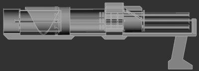
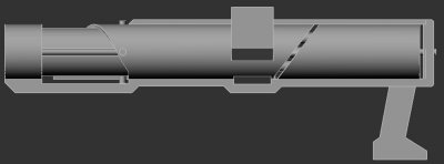
Okay I was going to keep this one under wraps but it's just too much fun. Carbon's simple Syringe Gun experiment gave me a serious epiphany that lead directly to this design. However, since the potential ROF is rather high for the configuration I decided early on that a large number of barrels and plungers would get to be too heavy to be managable. So I leaned my original concept down to just 4 barrels and a gravity-feed system to compensate for the lower number of barrels.
Posted Image
Posted Image
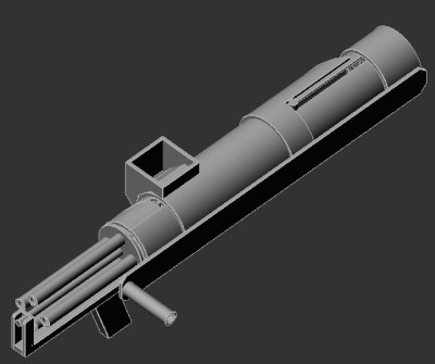
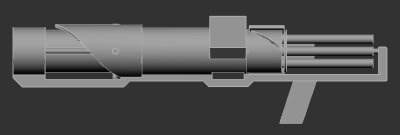
The barrel set will be powered by a cordless power drill with an adjustable clutch, which I will have to modify to move the handle/trigger/battery to the front of the gun but have the motor chucked onto the main axle in the rear of the gun. The plungers and brass breech covers will both be driven back and forth by helical tracks cut from large diameter PVC pipe or Acrylic scraps.
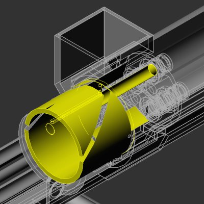
Here's the plunger and it's track.
Posted Image
And the 19/32 OD brass breech similar to what is commonly used for breech modifications.
Posted Image

And taking many cues from actual gatling guns I had to make a set of feeding teeth that pull the darts from left to right as the fall in order to guide them into the opened breech.
Posted Image
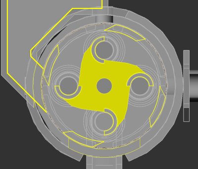
The shuriken-esque piece in the center makes sure that only one dart advances inward far enough to allow the stopping gate to close off the hopper before the next dart tries to enter. I also added an eject port to the bottom of this chamber so that in the event that I find that I have to use shells I can simply cut the breech shorter so that it acts only as a vice for the shells and then once the dart gets fire the shell can be dropped out of the bottom of the gun.
The eject port on the bottom also allows darts that failed to fire to be dropped to prevent jamming.

What I find quite strange after completing this design is that it would actually be easier to make than my other designs, but it could cost quite a bit more if I can't find the large OD PVC pipes as scrap and I can't find a cordless power drill on clearance. Each barrel assembly is designed around standard PVC pipe sizes and fittings and would only require minimal cutting with a bandsaw to add the breech hole and it's track.
Posted Image

Thoughts?

Edited by CaptainSlug, 25 August 2007 - 02:51 PM.

  • 0
The little critters of nature, they don't know that they're ugly. That's very funny, a fly marrying a bumble bee. I told you I'd shoot, but you didn't believe me. Why didn't you believe me?

#2 Maverick Master

Maverick Master

    Member

  • Members
  • 142 posts

Posted 24 March 2006 - 09:03 PM

That looks very interesting, but very complicated. If you can pull it off though it would be very cool.
  • 0
Cpt. Brian Scott of UGNS

Under
Ground
Nerf
Squad

Alias Scoped loser (+)
(.)(.) :)

LordofTheRings434
"In a sense, what I'm saying is that you shouldn't waste your time handling your balls. Go for the foamy rods instead."

#3 CaptainSlug

CaptainSlug

    Resident Mad Scientist

  • Administrators
  • 4,763 posts

Posted 24 March 2006 - 09:11 PM

The only thing that I forsee as being complicated is the dart feed system, which I will have to make first, probably as a scale model to get the feeding teeth shaped correctly.

Everything else is fairly simple otherwise since it doesn't involve having to make a trigger or a priming handle.
  • 0
The little critters of nature, they don't know that they're ugly. That's very funny, a fly marrying a bumble bee. I told you I'd shoot, but you didn't believe me. Why didn't you believe me?

#4 Carbon

Carbon

    Contriberator

  • Moderators
  • 1,894 posts

Posted 24 March 2006 - 09:17 PM

Great google moogly, look what the syringe hath wrought....

Very impressive, and pretty mechanically simple, considering. I just wonder about the kind of force and friction that the pullrod cam is gonna have to exert in order to pull it straight back. I'd think you'd need a slot guide that the pullrod could move straight back and forth in, with the helical cam underneath...so the cam can push the pullrod, and the slot can make sure that the force is channeled back. Just a thought.
  • 0
Hello. I am Indigo of the Rainbow Clan. You Nerfed my father. Prepare to die.

#5 GeneralPrimevil

GeneralPrimevil

    Member

  • Members
  • 578 posts

Posted 24 March 2006 - 09:42 PM

I see problems at high RPM...not that that will be a problem or anything since a cordless drill will have enough torque after so long to turn that chamber assembly...might I recommend a specialized system, or perhaps plugging it in?

Ummm...there's a lot of angles and parabolas involved in this...what do you have for machinery/tooling at your disposal?

Have you thought about just using a constant-pressure chamber assembly housing and a valve plate instead of the syringes? The only reason why I would recommend that over the syringes is because the hardest part is just getting everything lined up while keeping the rotators running smooth. After that, why have the multiple springs rob power from the main drive assembly? I'll try and elaborate later, if I remember...

Pretty good lookin' so far, just double check your work and abilities the whole way through design and construction...
  • 0
"Fear the man with one gun, for he probably knows how to use it."

#6 CaptainSlug

CaptainSlug

    Resident Mad Scientist

  • Administrators
  • 4,763 posts

Posted 24 March 2006 - 10:16 PM

Clarifications

I just wonder about the kind of force and friction that the pullrod cam is gonna have to exert in order to pull it straight back. I'd think you'd need a slot guide that the pullrod could move straight back and forth in, with the helical cam underneath...so the cam can push the pullrod, and the slot can make sure that the force is channeled back. Just a thought.

There is a forward-back track that the plunger "pin" travels through. The "pin" that the helical track acts against to move the plunger will be a threaded PVC pipe, probably with a metal washer to keep it at the correct height required to keep the pin in contact with the track.

I suck at math so I can't figure out what load on the track would be required, but I am thinking that to make things easier to prime I should make the plunger helical track so that it advances from 15deg-to-350deg instead of 180deg-to-350deg. That will shallow the angle quite alot and reduce the torque requirement.

Have you thought about just using a constant-pressure chamber assembly housing and a valve plate instead of the syringes? The only reason why I would recommend that over the syringes is because the hardest part is just getting everything lined up while keeping the rotators running smooth.


I forgot to clarify, but this will NOT be made out of syringes. The concept simply occured to me after reading the syringe gun thread. This is a fairly large gun and will be made almost entirely out of different PVC pipe sizes with AR-15 actions springs providing the power for the plungers. Basically EVERYTHING inside the gun will be spinning around and the barrels are spaced using frame plates that slide over and either glue or bolt onto the barrels.

After that, why have the multiple springs rob power from the main drive assembly?

Because they're simpler, especially in this configuration. Yes the friction is high, but a power drill can output more than enough torque to compress a 60lb load spring. The simplicity means I don't have to time valve firings or have any of the spinning parts line up to anything precisely in the cycle. If I need to alter the "center" of the cycle I can simply change where the helical plunger track ends and begins.

I see problems at high RPM...

This will not be rotated at much speed because the barrel set will fire one dart for every 90 degrees that it turns. I'm really only looking to achieve 20RPM (at first anyways), which is really slow. That would produce 1 shot every second if my brain is working that out correctly. This is where the clutch on the power drill comes in handy. And yes I could do plenty of testing with a corded power drill prior to mutilating a cheap cordless power drill. The power drill was the plan only because it's ridiculously cheap compared to having to purchase a motor, battery, and charger as seperate items.

Pretty good lookin' so far, just double check your work and abilities the whole way through design and construction...

Thanks.
And yes I have alot of tools I can play with including a basement full of power tools, acces to industrial bandsaws, mills, and a manual lathe. But if I simply make a paper template of the helical cuts they would be fairly easy to do with something as simple as a jigsaw. Most of the work will be done with a bandsaw, scrollsaw, and drillpress.

Edited by CaptainSlug, 24 March 2006 - 11:45 PM.

  • 0
The little critters of nature, they don't know that they're ugly. That's very funny, a fly marrying a bumble bee. I told you I'd shoot, but you didn't believe me. Why didn't you believe me?

#7 baghead

baghead

    Cheetos

  • Members
  • 1,366 posts

Posted 24 March 2006 - 10:17 PM

I love the Concept, but I'd like to see something more than renders from you one of these days. You have alot of work ahead of you, Best of luck on that.

Oh, and By The Way: the Nerfing Alliance of Radical Foam called the N.A.R.F. acronym over a year ago...

-Bags

Edited by baghead, 24 March 2006 - 10:19 PM.

  • 0

Don't call it a comeback, I never left.


#8 CaptainSlug

CaptainSlug

    Resident Mad Scientist

  • Administrators
  • 4,763 posts

Posted 24 March 2006 - 10:20 PM

Hmmm, well I'll start thinking of a new name. And yes I know I'm new to NERF mods and homemades. I'm taking my time to triple check everything before I start diving into my supply of plastic (and my wallet).

Edited by CaptainSlug, 24 March 2006 - 10:42 PM.

  • 0
The little critters of nature, they don't know that they're ugly. That's very funny, a fly marrying a bumble bee. I told you I'd shoot, but you didn't believe me. Why didn't you believe me?

#9 Greek Assassin

Greek Assassin

    Member

  • Members
  • 75 posts

Posted 24 March 2006 - 10:28 PM

Actually, 20RPM is i shot every 3 seconds. 60 RPM is a shot a second.
  • 0
QUOTE (Arcanis @ Apr 9 2005, 12:02 AM)
When I insert a dick, nothing happens.

#10 Carbon

Carbon

    Contriberator

  • Moderators
  • 1,894 posts

Posted 24 March 2006 - 10:33 PM

Actually, 20RPM is i shot every 3 seconds. 60 RPM is a shot a second.

Depemds on whether that R in RPM stood for "revolutions" or "rounds". If the machinery would be making 20 revolutionsPM, wouldn't that be 80 roundsPM (with four barrels?)
  • 0
Hello. I am Indigo of the Rainbow Clan. You Nerfed my father. Prepare to die.

#11 CaptainSlug

CaptainSlug

    Resident Mad Scientist

  • Administrators
  • 4,763 posts

Posted 24 March 2006 - 10:33 PM

Yes, I mean RPM as in revolutions per minute. If I want to discuss how quickly I'm firing darts I would use ROF to avoid confusion.

Actually, 20RPM is i shot every 3 seconds.  60 RPM is a shot a second.

Wouldn't 60RPM be 1 shot every second if only one barrel were spinning around? Since there are 4 barrels 90 degrees apart from each other it should work out to 15 or 20RPM.

And to help prevent confusion (hopefully) here's an image with all of the spinning parts highlighted.
Posted Image

Edited by CaptainSlug, 24 March 2006 - 10:40 PM.

  • 0
The little critters of nature, they don't know that they're ugly. That's very funny, a fly marrying a bumble bee. I told you I'd shoot, but you didn't believe me. Why didn't you believe me?

#12 m15399

m15399

    Member

  • Members
  • 146 posts

Posted 24 March 2006 - 10:49 PM

http://people.howstu...achine-gun4.htm
Eh?

It's a gatling gun for nerf. It's been done for bullets, air soft bb's, nerf, what next? ^_^
  • 0

#13 CaptainSlug

CaptainSlug

    Resident Mad Scientist

  • Administrators
  • 4,763 posts

Posted 24 March 2006 - 11:07 PM

Hehehe, yeah that was one of my references. I had to approach the darts feeding from the side instead of the top because fewer and larger barrels makes the distance that the darts would have to "fall" in order to get to the chamber would be too large for them to travel in the short amount of time between their entry and the firing at the end of the cycle.

I modified the plunger helical track so it now has a much shallower angle. I also got rid of the side handle because it was added to control something I finally decided doesn't need to be controlled.
Posted Image
Which translates to less torque persumably, but might not since more of the pins are on the track at the same time. Them being spring loaded means that unpowered the barrels will try to work their way backwards on the track because of the action springs but will stop when the pin at the end of the cycle runs into the end of the track.


Edit: New name is the CShG in honor of the GShG-7.62 which looks strangely similar in terms of proportioning.
Captain Slug's heavy Gatling

Edited by CaptainSlug, 25 March 2006 - 01:05 AM.

  • 0
The little critters of nature, they don't know that they're ugly. That's very funny, a fly marrying a bumble bee. I told you I'd shoot, but you didn't believe me. Why didn't you believe me?

#14 GeneralPrimevil

GeneralPrimevil

    Member

  • Members
  • 578 posts

Posted 25 March 2006 - 09:23 AM

More Russian stuff in Nerf...

Well, nice to know you dropped the syringes. You just replaced them with the same thing, only more powerful.

Ummm...just click the link...I drew that up awhile ago for a non-Nerf activity. If a Nerf system of feeding could be adapted, take the design or components for use with a constant pressure system. The only pressurized component would be the rubber hose leading from any solenoid valve to the breach plate which has a rotary-plate valve. The only timing is how precisely holes would be drilled in those two plates. The only resistance on that motor is what is used to turn the barrels. That is all;, nothing else robs power. Loading could be accomplished the same way that it would be for that design for spherical projectiles; a tube with a cam forcing a dart in once every 16.66 degrees. The darts could only be so long, however, probably closer to 1-1.5 inches.

What kind of drill are you using to power this thing? 4a? Even still, it might have torque to start the barrels, but power is still needed to keep the assembly turning.
  • 0
"Fear the man with one gun, for he probably knows how to use it."

#15 TT

TT

    Member

  • Members
  • 48 posts

Posted 25 March 2006 - 01:54 PM

http://people.howstu...achine-gun4.htm
Eh?

It's a gatling gun for nerf. It's been done for bullets, air soft bb's, nerf, what next? :w00t:

A gatling gun for potatoes maybe? I'd like to see that.

But back to the subject, this homemade gun would be an amazing piece of work. Of course it would be a lot of trouble to do it, but hey go for it man.
  • 0

#16 Meaker VI

Meaker VI

    Member

  • Moderators
  • 1,192 posts

Posted 25 March 2006 - 03:16 PM

And yes I could do plenty of testing with a corded power drill prior to mutilating a cheap cordless power drill. The power drill was the plan only because it's ridiculously cheap compared to having to purchase a motor, battery, and charger as seperate items.

I hope you aren't seriously planning on using a "cheap" cordless power drill. The cheap ones don't have any strength compaired to a mid-range dewalt or huskey. They can't even drive a screw in without having it pre-drilled. And the cheap ones' batteries run dry astoundingly quickly.

I am impressed with your attempts at designing something so stinkin' cool though; a fully automatic nerf weapon that doesn't need to prime... ever. All you'd need to do is reload the batteries with the clip/belt/whatever. I'm confident you'll figure out how everthing needs to work, though.
  • 0

#17 CaptainSlug

CaptainSlug

    Resident Mad Scientist

  • Administrators
  • 4,763 posts

Posted 25 March 2006 - 06:08 PM

take the design or components for use with a constant pressure system.

Since you posted your comment I've been thinking about several alternative dart loading mechanisms that would be much MUCH simpler to make so thanks for that atleast.
It took a while but I think I've figured out basically what you're saying and how it might be possible to make so that it's self-charging but since I want each shot to have the same range I can't figure out any method of implementing a non-spring-plunger system that would require less torque. Each barrel needs to have it's own supply of pressurized air because there's not enough force or cycle length in a 90-degree rotation to both charge and release a workable amount of pressure. Using the same pressure tank between 4 barrels will lead to a slow decrease in range.
I guess I need to start doodling...

Edited by CaptainSlug, 25 March 2006 - 06:40 PM.

  • 0
The little critters of nature, they don't know that they're ugly. That's very funny, a fly marrying a bumble bee. I told you I'd shoot, but you didn't believe me. Why didn't you believe me?

#18 GeneralPrimevil

GeneralPrimevil

    Member

  • Members
  • 578 posts

Posted 25 March 2006 - 06:58 PM

I was thinking just keeping it hooked up to an air compressor, as in, a large 20 gal. 5hp compressor. That would keep up with demands of anything. It would limit the effective use, but...
  • 0
"Fear the man with one gun, for he probably knows how to use it."

#19 CaptainSlug

CaptainSlug

    Resident Mad Scientist

  • Administrators
  • 4,763 posts

Posted 25 March 2006 - 07:36 PM

Yeah, I want to avoid having to limit this to being corded or stationary. I designed it to be shoulder-mounted and autonomous. I'm not trying to make a weapon that can fire a wall of darts or have an insane rate of fire. I'm at the very least designing a weapon that primes itself and fires in a continuous cycle without requiring a crank or any complicated machining. If it turns out that it can handle a higher rate of fire then hooray, but that's not really the goal.

Edited by CaptainSlug, 25 March 2006 - 08:58 PM.

  • 0
The little critters of nature, they don't know that they're ugly. That's very funny, a fly marrying a bumble bee. I told you I'd shoot, but you didn't believe me. Why didn't you believe me?

#20 GeneralPrimevil

GeneralPrimevil

    Member

  • Members
  • 578 posts

Posted 25 March 2006 - 08:45 PM

Oh, okay then.

If I didn't have so many projects to have to do, I'd start work on one. So far, I've been forced to lighten my load. Now I just have to: finish coaxial homemade, SNAP knock-off, practice bomb, sounds system, and a few other thinds I need in the months of June and July.

Well, good luck, again...
  • 0
"Fear the man with one gun, for he probably knows how to use it."

#21 SKIZ

SKIZ

    Member

  • Members
  • 65 posts

Posted 26 March 2006 - 12:15 AM

Hey sounds great!!

ive built something like this before with a mate but unfortuantlly the power involved in the springs compared to the strenght of the spring housing was just to great and gave way. Havnt attempted to rebuild just used the remains for scrapes.
Just some pointers:
1. Remember that the barrels are spinning and that means timing of when the plunger has enough power to fire the dart will have to be thought about as yo may pver shoot your mark. I.E. spining clockwise: you want to fire at 12 "o" clock, if not timed corectly you will shoot at 1 "o" clock.
2. plungers have good enough power if you have a king shit spring behind them, but make sure you learn from my mistake and make the spring housing strong.
3. If you use cams to pull your plunger back the force required to pull will be dampened. (mechanical advantage)
4. Instead of using a motor whats wrong with a geared handle?
5. No shells required so only one hole to worry about. (the feeding hole) make sure this is covered before firing or lots of pressure lost.

This is only rough but really really really basic picture of how to go about a firing mechanism. I know you can see something very similar on www.howstuffworks.com but meh just trying to help.

Posted Image

Of coarse yours would need to be cilindrical and look different to the pic but you get the jist of what needs to be done.
Hope you can get this done because i wouldnt mind making my second atempt at one of these. (gattling gun)
looking forward to your work ^_^

Edited by SKIZ, 26 March 2006 - 12:17 AM.

  • 0

#22 CaptainSlug

CaptainSlug

    Resident Mad Scientist

  • Administrators
  • 4,763 posts

Posted 26 March 2006 - 01:06 AM

1. Remember that the barrels are spinning and that means timing of when the plunger has enough power to fire the dart will have to be thought about as yo may pver shoot your mark. I.E. spining clockwise: you want to fire at 12 "o" clock, if not timed corectly you will shoot at 1 "o" clock.
2. plungers have good enough power if you have a king shit spring behind them, but make sure you learn from my mistake and make the spring housing strong.
3. If you use cams to pull your plunger back the force required to pull will be dampened. (mechanical advantage)
4. Instead of using a motor whats wrong with a geared handle? 
5. No shells required so only one hole to worry about. (the feeding hole) make sure this is covered before firing or lots of pressure lost.

1. All you have to do is make the track with the width of the pin in mind and the time it takes for the plunger to fire. It doesn't really matter if the plunger fires a little bit off from the position it needs to be at because the plunger is spinning with the barrel and the dart.
2. The plunger house will be 1" PVC
3. yeah
4. Not as much fun
5. Each barrel has an actuated breech which closes over each dart prior to the plunger release and then opens after the plunger fires in order to accept a new dart.


I've simplified the design a bit further and the gun should only cost about $50 in materials plus the cost of whatever cordless power drill I decide upon using or find on the clearance rack. It will use 4" PVC, 1" PVC, 1/2" PVC, 19/32 brass, 9/16 brass, and 3/16" polycarbonate sheets.
Posted Image
Here's the revised barrel and plunger assembly
Posted Image

Edited by CaptainSlug, 26 March 2006 - 04:03 AM.

  • 0
The little critters of nature, they don't know that they're ugly. That's very funny, a fly marrying a bumble bee. I told you I'd shoot, but you didn't believe me. Why didn't you believe me?

#23 SKIZ

SKIZ

    Member

  • Members
  • 65 posts

Posted 26 March 2006 - 02:01 AM

Well looks all good
seems that you have looked at all aspects. Please post plans if you manage to pull this off because as i said really interested in miniguns (using a motor so mini gun, manual turn means gattling gun) and also to see how your model will differ from mine.

Just a quick question though how are you going to cover the breech?
And another quick hint: makes lots of darts now!!! This thing should chew through darts like theres no tomorrow.
  • 0

#24 CaptainSlug

CaptainSlug

    Resident Mad Scientist

  • Administrators
  • 4,763 posts

Posted 26 March 2006 - 03:26 AM

Just a quick question though how are you going to cover the breech?

It took quite alot of time to figure out but I'm going to nest 9/16 brass into 19/32 brass then stick that into 1/2" PVC. The brass becomes the barrel, and the PVC simply becomes a jacket for the barrel/breech to slide inside of.
The barrel is actuated as a breech to push the dart backwards 1/4"-inch and it gets wedged into the end of the breech/barrel. This allows the PVC to be cemented to the plunger tank and frame pieces. This ends up being a simpler and smaller enclosed mechanism than the zero-style PVC breech.

The brass is yellow in this image.
Posted Image

I'm also considering adding a small 17/32 brass piece to act as a snug collar to hold the darts firmly as the pressure builds.

Edited by CaptainSlug, 26 March 2006 - 03:29 AM.

  • 0
The little critters of nature, they don't know that they're ugly. That's very funny, a fly marrying a bumble bee. I told you I'd shoot, but you didn't believe me. Why didn't you believe me?

#25 SKIZ

SKIZ

    Member

  • Members
  • 65 posts

Posted 26 March 2006 - 03:53 AM

It took quite alot of time to figure out but I'm going to nest 9/16 brass into 19/32 brass then stick that into 1/2" PVC. The brass becomes the barrel, and the PVC simply becomes a jacket for the barrel/breech to slide inside of.
The barrel is actuated as a breech to push the dart backwards 1/4"-inch and it gets wedged into the end of the breech/barrel. This allows the PVC to be cemented to the plunger tank and frame pieces. This ends up being a simpler and smaller enclosed mechanism than the zero-style PVC breech.


FUCK!!! I dont get any of that. sorry. I think i MIGHT understand but how is it going to open and close on demand?
  • 0


1 user(s) are reading this topic

0 members, 1 guests, 0 anonymous users