Jump to content


Photo

Computer Vision Accuracy Measurement Software


10 replies to this topic

#1 shardbearer

shardbearer

    Member

  • Members
  • 177 posts

Posted 16 January 2018 - 06:35 PM

Thantacles, MTB Ryan and I have been thinking for a while about how to empirically and efficiently measure the accuracy of various darts and blasters. The advent of chronographs and widespread fps testing has sparked an arms race in blaster performance, but for accuracy testing we're still mostly going by gut feel, or measuring how many darts hit a target at a certain distance, which is never the same between two people testing. The accuracy testing that Bobololo and Coop have done in their videos is great, but extremely time consuming, because they go through the video footage and mark the location of every dart hit by hand. We've thrown around ideas ranging from shooting a sheet of Play-doh to a big sensor grid based on capacitive or resistive touchscreen technology. But the one that seems to show the most promise so far is Computer Vision. Here's the criteria:
 

Low hardware cost and construction time, so that this can catch on and we start seeing more empirical accuracy data. Giant sensor walls would require significant time, experience, and hardware to build.
 

Empirical, with large data volumes. Not subject to people's aim. Additionally, having more data is better, eg the location of every dart on a target is better than just a group size number which is liable to subject to outliers, or a number for what percentage hit the target.

Low testing effort. Play-do or inked darts require setting up for every test, and then you have to manually digitize them. You're probably not going to bother recording the location of every dart, and just measure group size, which doesn't give you as much to work with.
 

So the solution we came up with on Sunday was to shoot the darts against a white wall, and place a microphone on that wall to record the impact of each dart. Take a video of the whole thing, and extract the frames that correspond to the audio spikes when the dart hits the wall, and then do a computer vision analysis of those frames to get a location for every shot. I've never done computer vision before, but I hear the OpenCV Python library makes it fairly straightforward. Let me know if you're interested in helping.


  • 0

#2 Ming Batt

Ming Batt

    Member

  • Members
  • 12 posts

Posted 16 January 2018 - 10:16 PM

I think you can streamline this process a bit more to have your computer do all of the work. As you said, a simple mic placed near the wall, plugged into your computer to record when the dart hits the wall will work perfectly. A webcam, either the laptop's or an external one, faces the white wall. Maybe put an object in the center of a different color than the dart for the blaster to aim at. At the start of the execution of the program, OpenCV can look for this centering object for reference later on. The python program, using a real-time audio analysis library (checkout pyAudioAnalysis: https://github.com/t...pyAudioAnalysis or librosa: https://github.com/librosa/librosa), will listen for when a dart hits the wall. When the dart hits, use OpenCV to look for the dart (super simple, use color or something) and save those coordinates. With these coordinates (as well as the coordinates of the centering object), use a simple 2d drawing library to draw all the points. Since you have the position of every dart and the center point, you can do some maths for some cool statistics.


EDIT: spelling


Edited by Ming Batt, 16 January 2018 - 10:17 PM.

  • 0

#3 TantumBull

TantumBull

    Member

  • Moderators
  • 1,929 posts

Posted 19 January 2018 - 07:05 PM

I recommend taking a look at home-brew darts scoring system. Darts like you throw onto a target at a bar, not nerf darts. A quick google search yielded the following:

Using webcam: http://hamblen.ece.g...Darts/home.html

Facebook group that shares code and ideas: https://www.facebook...98914107/about/


If it were me, I would take a machine learning approach with microphones around the target. The system records volume level from each mic, stores in integer array. Something like Analog.read could achieve this in arduino. Then pull the array into Python and run a ML algorithm. The problem is simple enough that a least squares approach should work, as there shouldn't be a whole lot of sensor drift. If you want to save on time by not writing as much of the algorithm, there are pre written ML packages in Python. And there is software that will take serial out from Arduino and bring it into Py for math. Keep in mind that this approach would tether it to your comp. Arduino likely isn't powerful enough to invert matrices etc, so if you didn't want it tethered you could use a Pi. The hardest part would be generating a training set, for which you would likely have to take the same approach the youtubers you mentioned do. The key here is you only have to do it once or twice.


  • 0

#4 shmmee

shmmee

    Member

  • Members
  • 467 posts

Posted 30 January 2018 - 03:15 PM

Visual tracking has a whole other host of complications. The camera has to be able to recognize and follow the dart, the accuracy would be limited by frame rate and recognition.


Theirs another direction I'd like to suggest for this problem. Acoustic emission and Ultrasonic time of flight.


I work in NDT (non destructive testing) and specific technologies exists to track the active progression of cracking and erosion in pressure vessels is Acoustic emission. It basically involves epoxying multiple microphones onto a surface and listening for the object to make noise and then triangulating the location of the noise by recording the time it took between each microphone to pick it up. I'm told the industry was pushing the technology pretty hard in the late 90's but it never really took off because it was so specific in it's use. You had to know a crack was present before you would bother listening for it. Acoustic emmision is a spin off of Ultrasonic testing. Ultrasonic testing uses a transmitter to induce an ultra sonic sound into the wall of a part and times how long it takes for that signal to travel to the end of the wall and bounce back to the transmitter. It can measure thicknesses down to the .001" of an inch and is widely used in the industry today. (especially in the medical industry). 


Instead of a complicated video set up, maybe 3 microphones and some slick programming can duplicate the same result? If professionals can "listen" to a crack growing in a vessel, maybe we can track and plot the location of a thud on a dry erase board with a few piezo electric elements? Heck, we could even add a fourth element onto a blaster barrel attachment and pull a fps by knowing the distance between the blaster and the white board and timing the travel between the first thud (blaster firing) and second thud (dart hitting the board). Knowing the actual time of flight between barrel and board would also measure dart drag. Most of our chrony values are measured at the barrel (where we can reliably hit the chrony window), which is great for grading a blaster, but poor for grading a dart. Knowing time of dart flight would introduce a whole new way to grade actual and specific dart performance beyond accuracy. 


Such a set up could even keep up with blasters in full auto mode and plot data instantly. 


Sound travels through different materials at different speeds so there would need to be some calibrating involved, but that would be as simple as "thudding" the board next to one microphone and carefully measuring the distance and time to another mic. Once we establish that sound travels [x] fps in what ever material is being used, the rest is programming and math. 


Sound waves also bounce inside solid materials so there might need to be some sensitivity adjustments or sound deadening channels behind each microphone as well. 


Edit: : Might be needing to use trilateration (not triangulation) since trilateration also involves distances from known reference points. Wikipedia refference:

https://en.wikipedia...i/Trilateration


Edited by shmmee, 30 January 2018 - 05:29 PM.

  • 0
"and we should respect the people who make our blasters. Even if we do molest the hell out of them..."
~BritNerfMogul


#5 TantumBull

TantumBull

    Member

  • Moderators
  • 1,929 posts

Posted 30 January 2018 - 07:46 PM

I like that more than my idea.


With some back of the envelope math, if you wanted say 1" resolution and assuming that speed of sound through air is sufficiently slower than the medium that makes up your target, you would need timing accuracy of about 75 microseconds. That's extremely reasonable even with something as simple as an arduino. I like that a lot.


A quick note about measuring sound through the target medium, as shmeee suggests, is you would need to differentiate between the wave spike from sound through air and sound through board. However, assuming your delta SOS is sufficiently large, this is acceptable. It would obviously only make sense to take this approach if the sound through your target medium is less than that through air. Let's take some arbitrary rubber and assume SOS is 150 m/s. You would now need timing accuracy of abs( 75us - (.0254 m / 150 mps)) ~= 94us to discern the difference in pulses. You would only need .(0254/150) = 169us for the 1" resolution discounting the singnal from the air. You can see here how if the rubber instead had a SOS of something like 300, you would need wildly more accurate sampling than if you simply went with a solid wood backing (sufficiently high SOS that initial wood pulse is relatively far out from air pulse).


Basically be careful choosing your target medium. If your system can also take into account volume and filter out the same pulse from one medium or another, then this is a non-issue.


Edited by TantumBull, 30 January 2018 - 07:46 PM.

  • 0

#6 shmmee

shmmee

    Member

  • Members
  • 467 posts

Posted 31 January 2018 - 09:57 AM

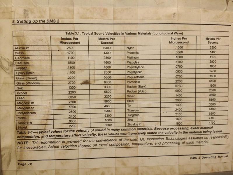
Here's the sound velocities chart from the inside of my clipboard. Obviously, it's not complete but might be helpful as a point of reference for some ball park values. For this project we should probably be looking for slower values, but not so slow that we loose too much volume due to attenuation. I'm attaching it just to show how wildly values can change between materials. And because it's geeky cool. It's always surprised me how much variation there is between materials - and even between metals.


Base line: sound traveling through air: only 343 meters per second. Wacky, but sound travels through solids waaaay faster than through air. Hopefully this is still within the realm of an arduino.


Of the values listed, Plexiglas might be our best bet with a pretty reasonable 2800 meters per second. I'm still curious about the viability of MDF/pressboard/dry erase board (because of cost) but theirs a very real chance that the pressed construction of the material might fail to transmit sound at a reasonable distance. Plexiglas is also tempting because epoxy resin is also 2800 meters per second. The identical transmission speed should be crazy helpful getting sound from the board into the probes. The bigger the difference in transmission speeds, the more loss there is as it passes through boundaries.


In respects of differentiating between a pulse from the blaster firing to the dart hitting the board, it's not something we will probably have to worry about. As sound is passed from air into a medium most of it is reflected back instead of being absorbed into the part. Even with ultrasonic couplant (a specialized jelly with the viscosity of snot - which also works as a couplant (it was cold, i ran out of couplant, had 2 readings left and was NOT going to climb back to the top of that 85' tower!) only 11% of the energy from an ultrasonic transducer actually makes it into the test subject and the other 89% is reflected back into the transducer. We should be able to do much better with an acoustic driver like a nerf dart smacking into a target and shouldn't have to worry at all about the board picking up the sound of the baster firing. Though, holy crap that would be cool if we could! With a carefully measured distance from the blaster to the target, if the board could "hear" the blaster firing, we could use that initial pulse to establish a chronographed measurement of the dart and establish dart drag - without a 4th listening element wired up to the blaster! In all honesty, I think we'll have more trouble with picking up multiple instances of the initial sound wave bouncing back and forth within the sheet  than external interference like ambient noise or blasters firing. 

Attached Thumbnails

  • IMG_20180131_0721061.jpg

Edited by shmmee, 31 January 2018 - 12:12 PM.

  • 0
"and we should respect the people who make our blasters. Even if we do molest the hell out of them..."
~BritNerfMogul


#7 shmmee

shmmee

    Member

  • Members
  • 467 posts

Posted 31 January 2018 - 10:18 AM

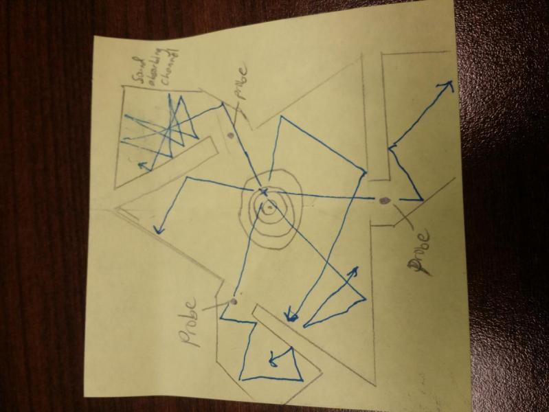
We should probably be just as picky about the shape of the board as the material. It's a rough sketch, but if we have something like this, we might be able to tune the shape of the board so reflected sound waves are only hitting the probes once and most of the secondary waves are either reflected away from the probes, or are absorbed behind the probes.


Attached Thumbnails

  • IMG_20180131_0813361.jpg

Edited by shmmee, 31 January 2018 - 10:21 AM.

  • 0
"and we should respect the people who make our blasters. Even if we do molest the hell out of them..."
~BritNerfMogul


#8 TantumBull

TantumBull

    Member

  • Moderators
  • 1,929 posts

Posted 31 January 2018 - 03:36 PM

I should have clarified, when I was talking about differentiating air sound from board sound, I was talking about sound of dart hitting board travelling through air vs. sound of dart hitting board travelling through board. Not sound of blaster vs. sound of dart impact, those two spike will be miles away at the scale we are considering. If your SOS through the board is close to that through air, you are going to have real problems differentiating the two unless the peaks of the spikes are sufficiently different i.e. different volume.


What I'm advocating is measuring sound of dart hitting the board through air with a sufficiently high SOS board material.


Taking Shmee's suggestion of picking up the sound transmission through the plexiglass, and if we wanted 1" resolution on the target, our a sample frequency would need a minimum period of 9us. This is actually within reason for an arduino, but would either require a dedicated timer IC or a better timing function than micros(), which has 4us resolution. There are tricks available involving using interrupts to time PWM signals, and I believe that can get you down to 0.5us for timing. Unfortunately reading the signal constantly puts us out of our target period, as each instance of digitalRead() take 1 or 2 us. Even worse if we don't amplify the signal and use analogRead().


tl,dr: Measuring through air would likely allow something as simple as an Uno. Measuring through board material, unless significantly lower SOS than air (see my previous post), will almost certainly require a Pi or full on PC.


  • 0

#9 shmmee

shmmee

    Member

  • Members
  • 467 posts

Posted 31 January 2018 - 04:34 PM

I should have clarified, when I was talking about differentiating air sound from board sound, I was talking about sound of dart hitting board travelling through air vs. sound of dart hitting board travelling through board. Not sound of blaster vs. sound of dart impact, those two spike will be miles away at the scale we are considering. If your SOS through the board is close to that through air, you are going to have real problems differentiating the two unless the peaks of the spikes are sufficiently different i.e. different volume.


What I'm advocating is measuring sound of dart hitting the board through air with a sufficiently high SOS board material.


Ah, Thanks for clarifying. That makes a lot more sense. I guess I'm so hardwired into the theory of ultrasonic properties, that i had somehow forgotten that sound still travels through air at a constant and measurable rate, and that a dart hitting a board makes a significant sound. It would definitely be easier to go with the much slower velocities of air conduction rather than overhauling hardware for ultrasonic speeds. Measuring through air would also let us pick up the sound of the blaster firing to establish dart speed and drag if we wanted to get the extra data. 


  • 0
"and we should respect the people who make our blasters. Even if we do molest the hell out of them..."
~BritNerfMogul


#10 shmmee

shmmee

    Member

  • Members
  • 467 posts

Posted 02 February 2018 - 10:31 AM

Even though the math, science and technical level is well above my experience level, at least I can google. Here's some ground work discussion already laid by others...


https://forum.sparkf...hp?f=14&t=24738


https://electronics....ection-position


https://playground.a...n/Triangulation


https://en.wikipedia...i/Trilateration


  • 0
"and we should respect the people who make our blasters. Even if we do molest the hell out of them..."
~BritNerfMogul


#11 meow121325

meow121325

    Member

  • Members
  • 125 posts

Posted 15 February 2018 - 10:38 AM

I might be able to make this problem a lot simpler have sets IR receivers and transceivers a set for the y axis and a set for the x axis have them hooked up to a computer then have the IR sensors flush to a wall and fire the darts at the wall when a signal is interrupted by a dart it will show up as a point on a grid program then that way you don't have to worry about complicated set ups and you don't have to spend a lot of money you just need 2 busted DVD players and their remotes and extract the sensors the sensor in the DVD players are receivers and the sensors in the remotes are transceivers 


  • 0


0 user(s) are reading this topic

0 members, 0 guests, 0 anonymous users