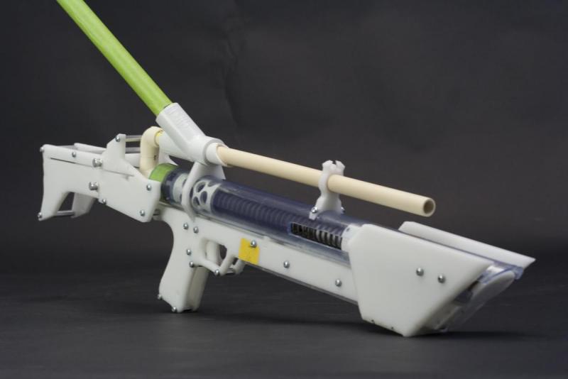
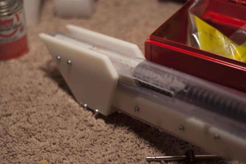
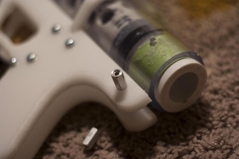
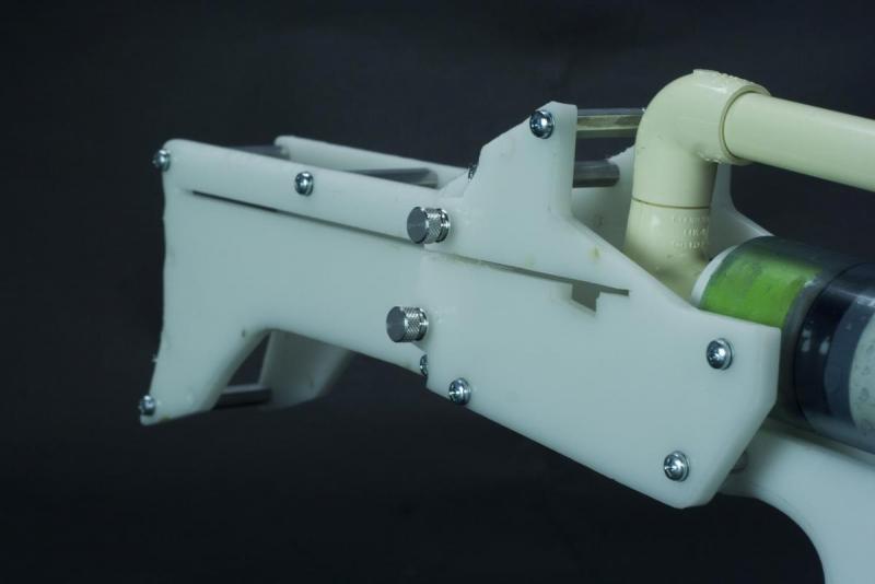
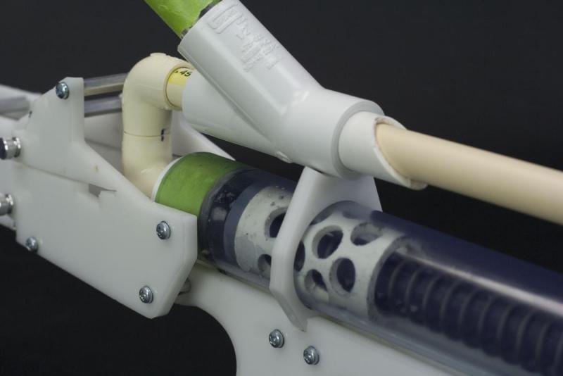
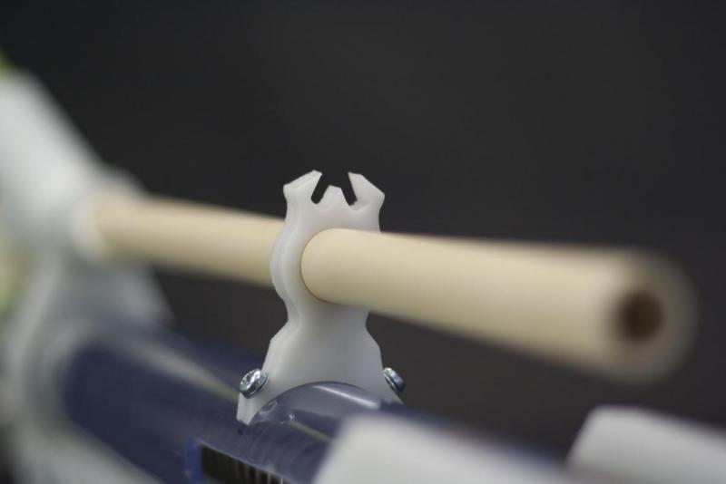
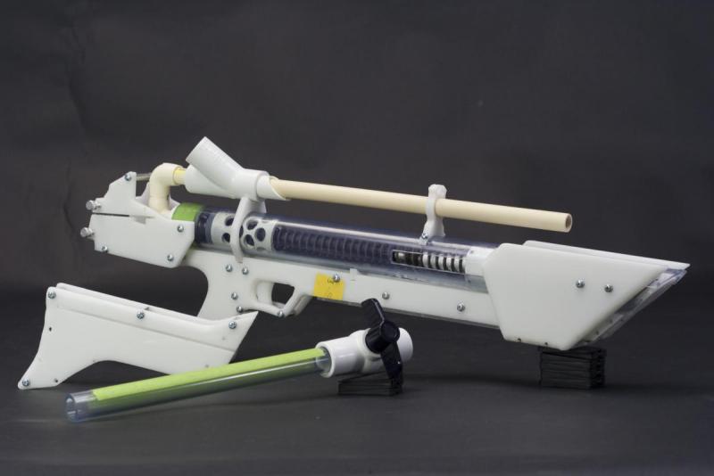
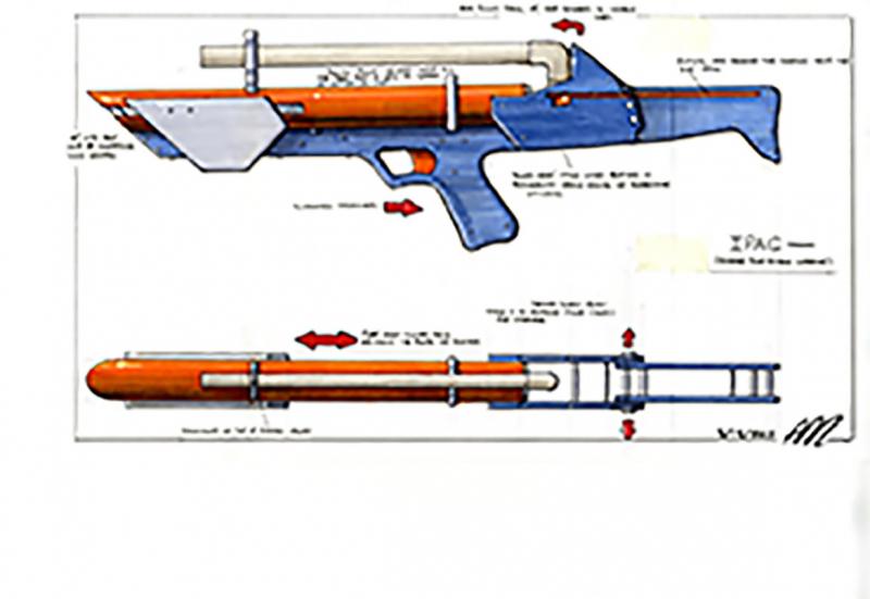
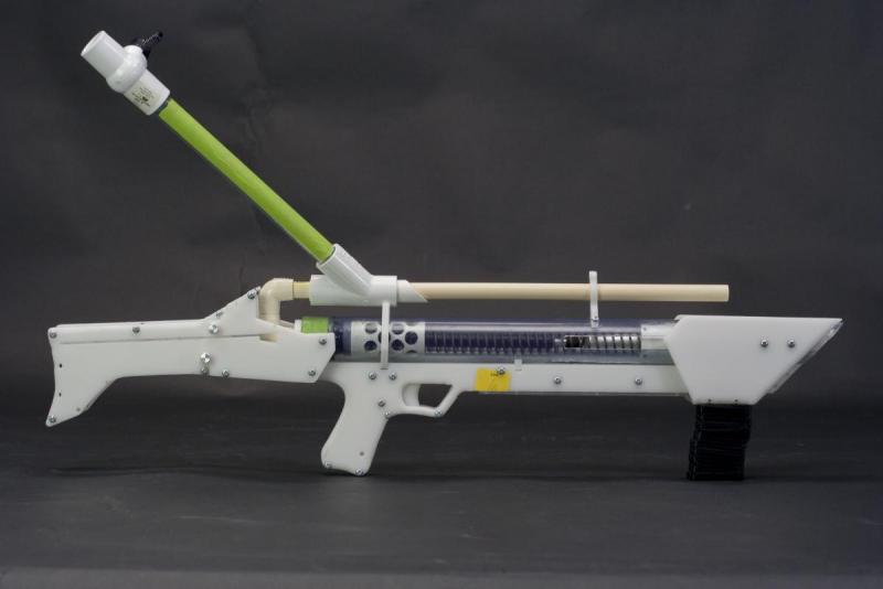
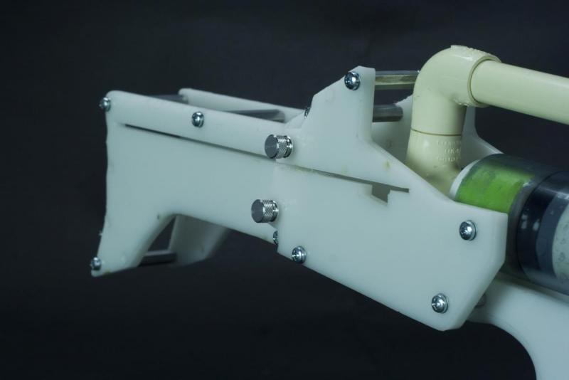
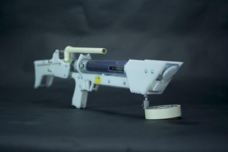
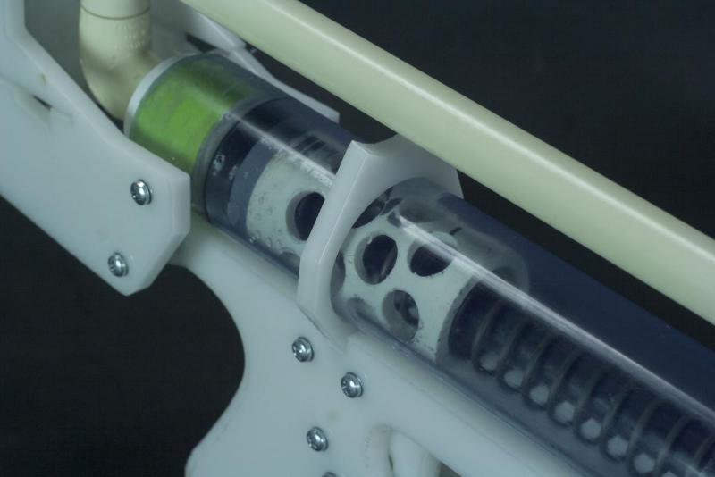
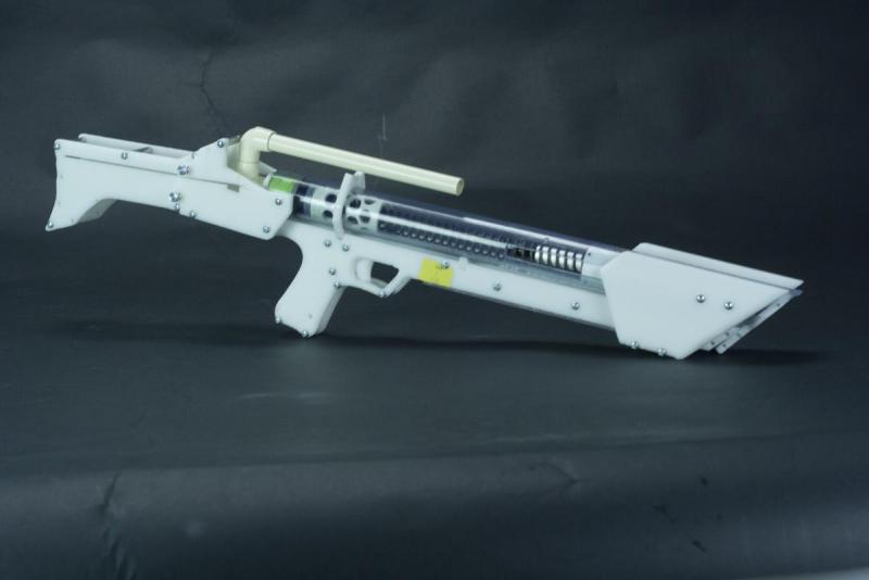
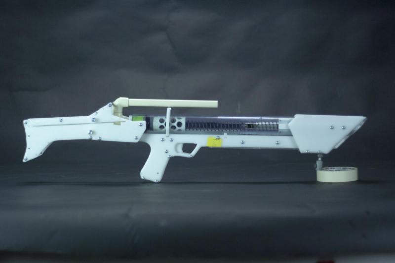
FORWARD: The goal of this design was to create a prototype blaster and treat it as a product for sale in stores utilizing the design method for use in my design portfolio. With the help of research from the community here, not only did I succeed in building this prototype blaster, but I have found many innovations through this process that I hope can benefit in the community. Those who helped directly via email, or by filling out my survey, thank you. Also a huge thank you to Captain_Slug for the recent revolution of homemade design that greatly impacted this process. Now, onto the writeup.
Going back as far as I can remember with homemade blasters, a large majority of people’s work has been purely functional; nerf blasters were too weak and the parts weren’t durable enough for our needs, so hardware store parts and piping made a proper substitute. Due to the ready-made nature of using pre-made parts, form and ergonomics weren’t a consideration until after functionality was developed. Aesthetics and performance were, and continued to be two separate focuses in homemade blaster design, which limited how far this process could be taken. Over the past few years, more focus has been put into ergonomics, but the form of homemades still has been very lacking. Not until the Caliburn and the increasing use of 3D printing has thoughtful consideration of form been established. We still have more work to go, but I hope this blaster becomes a trailblazer in functionality, and form giving in homemades with the hope it inspires and proves that you don’t need a 3D printer to make a blaster with thoughtful form-giving.
Based on the research drawn from the community’s engagement, I have found solutions to popular problems of large majority, as well as adding some finer nuances to homemade blasters:
-
Form over function-give it a proper look. I ended up taking an aggressive approach to its form
-
Availability to break down for transportation/storage
-
Reduce the overall size, and have the barrel mounted within the overall body length of the blaster for storage and maneuverability in the field
-
Better ergonomics and safety for the user (trigger guard and in the future, trigger lock)
-
Functionally- needed to have a smooth operation, performance and more (integrated ‘slam-fire’)
-
Ease of break down for maintenance
-
Utilize similar parts as other popular writeups (Captain_Slug’s work) to allow interchangeability of parts within community builds
-
Durability
TOOLS NEEDED:
-
Phillips Screwdriver
-
Allen Wrench
-
Drill with 5/32”, 7/64”, 9/16”, ⅝”, ½” Drill bits
-
Dremel with sanding drum and metal cutting disk
-
File/sandpaper
-
PVC Cement
-
Plumber's Goop
-
Tapping set and a 6-32 (7/64”) tapping bit
-
Masking Tape
-
Clear Scotch Tape
-
Printer/printer paper
-
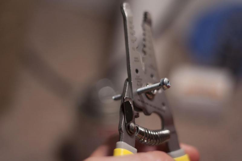
Wire Cutter with 6-32 screw cutting holes
-
Scissors
-
Exacto knife/box cutter
PARTS LIST:
Part McMaster Part Number Optional
½” Threaded Standoffs (3) 91125A445
Catch Spring 96565K36
¼” Allen Screws 94355A144
½” Allen Screws 94355A148
Extension Spring 9654K973
½” Lock Screws 90403A148
1 ½” Lock Screws 90403A157
[[[[[[[[[[[[[[[[[[[[[[[[[[[[[[[[[[[[[k26]]]]]]]]]]]]]]]]]]]]]]]]]]]]]]]]]]]]] 9637K26
Spring
Skirt Seal 9562K46
⅛” Aluminum Bar 4490T171
½” Thumb Screws (4) 93585A015 Optional
⅝” Aluminum Pipe (2ft) 1658T11
½” Black Delrin 8576K15
Rubber Gasket 90133A420
¼” CPVC sheet (6x6) 8748K118
½” Aluminum Hex 91780A127
Standoffs (9)
2” Aluminum Hex 91780A339
Standoffs (3)
1 ½” Aluminum Hex 91780A337
Standoffs(9)
1 ¼” Clear PVC (4ft) 49035K21 Optional
¼” Polycarbonate sheet 8574K43
12x24”
¼” Delrin sheet 12x24” 8573K35 Optional only if you plan to laser cut parts. Don’t buy polycarb if so
Aluminum Unthreaded 92510A445
Spacer (1)
⅛” Acrylic Sheet 8560K275
1” PVC (2ft)
1 to ½” Reducing Bushing
½” CPVC (2ft)
½” CPVC Elbow (2)
½” PVC (1ft)
Now that the formalities are out of the way, now let’s get to the fun stuff.
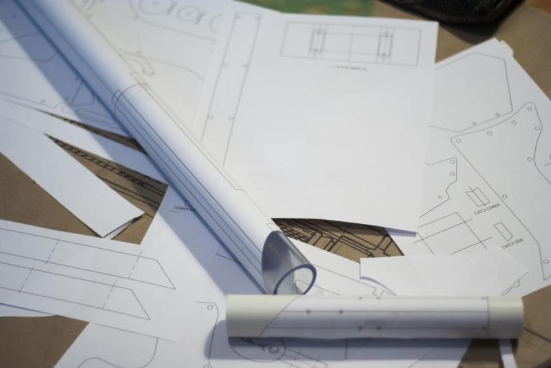
This blaster has a lot of measurements and parts that need to be accurate in order to work correctly. To make things a little easier, I made a PDF file of all of the templates I created for the blaster which are available HERE:  PRINT_IPAC_Templates.pdf 906KB
772 downloads. I have also created a vector file for the templates not for PVC that can be laser cut if you have one available to you which can email me or PM me if you'd want that file. NOTE- if you choose to laser cut the templates you CANNOT use polycarbonate. Use the Delrin listed in the parts list. Otherwise, use polycarbonate. It’s cheaper.
Part 1: Templates
PVC:
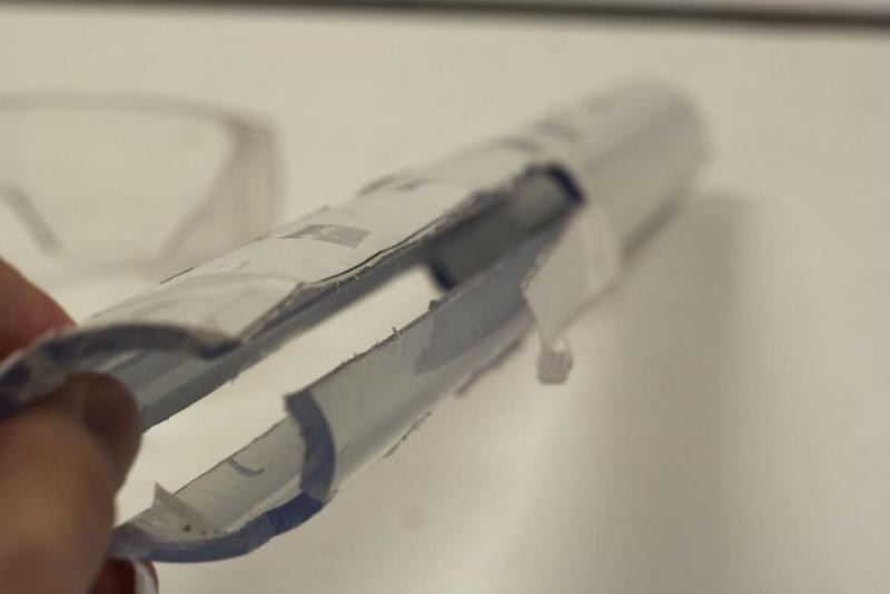
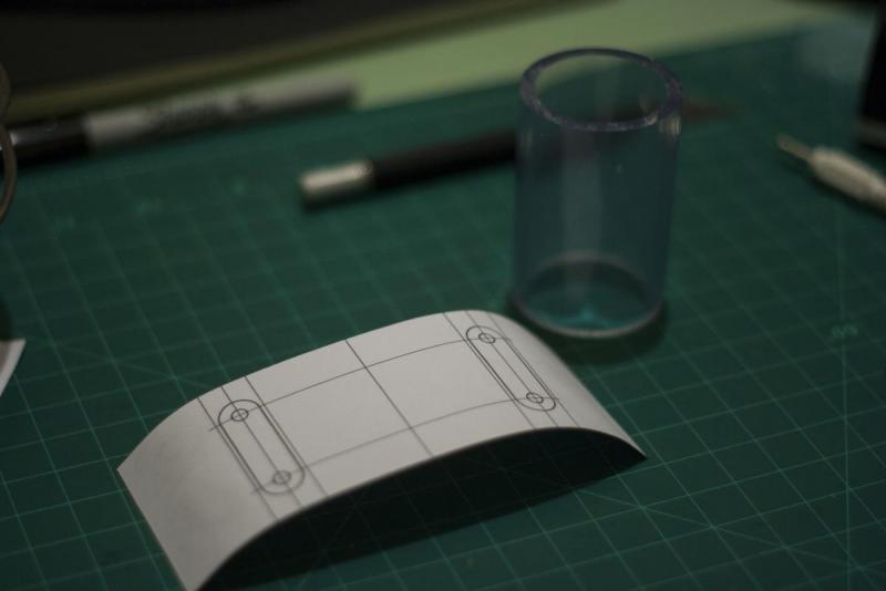
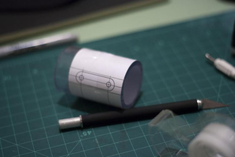
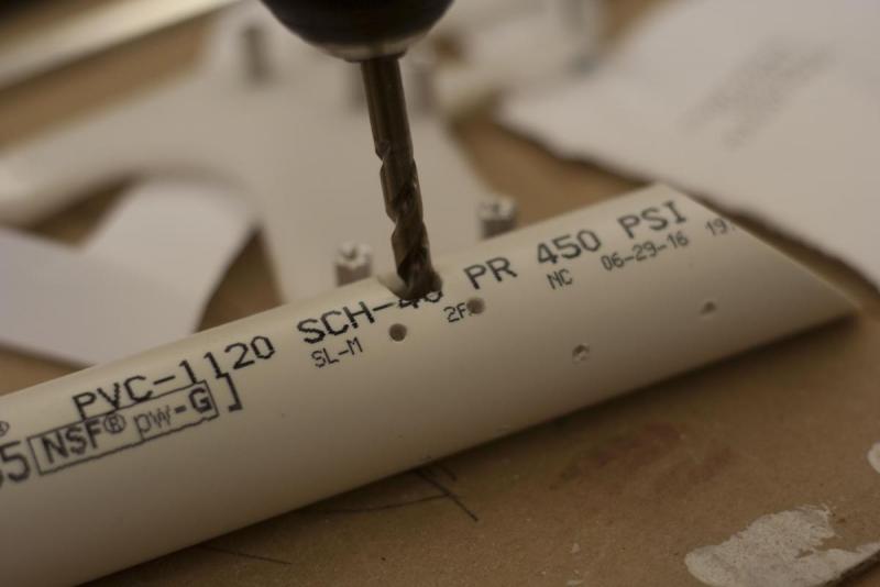
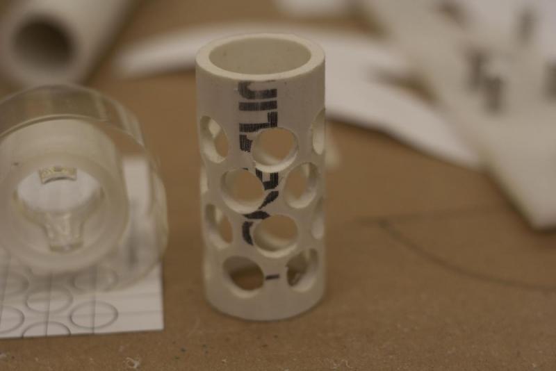
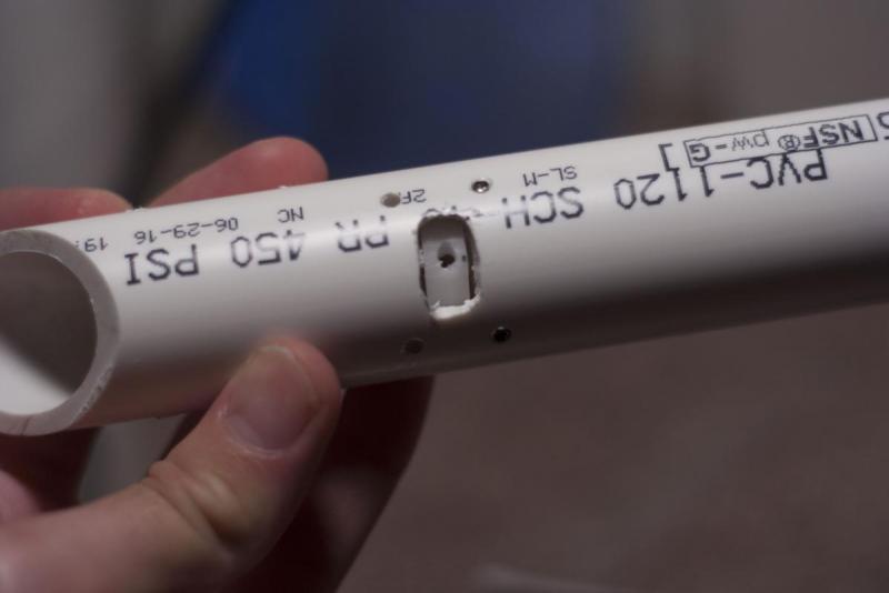
Start by cutting out the PVC templates, taping the templates that are listed as parts of a bigger template size together, and wrapping them around the suggested PVC with tape. Cut along the seams with your dremel, bandsaw, or scroll saw and use the proper drill bits where they are listed. I’d recommend drilling pilot holes with a much smaller drill bit first, or use a nail and hammer on the center of each hole and lightly tap a small indention into the PVC so the drill bit has a point to grip into.
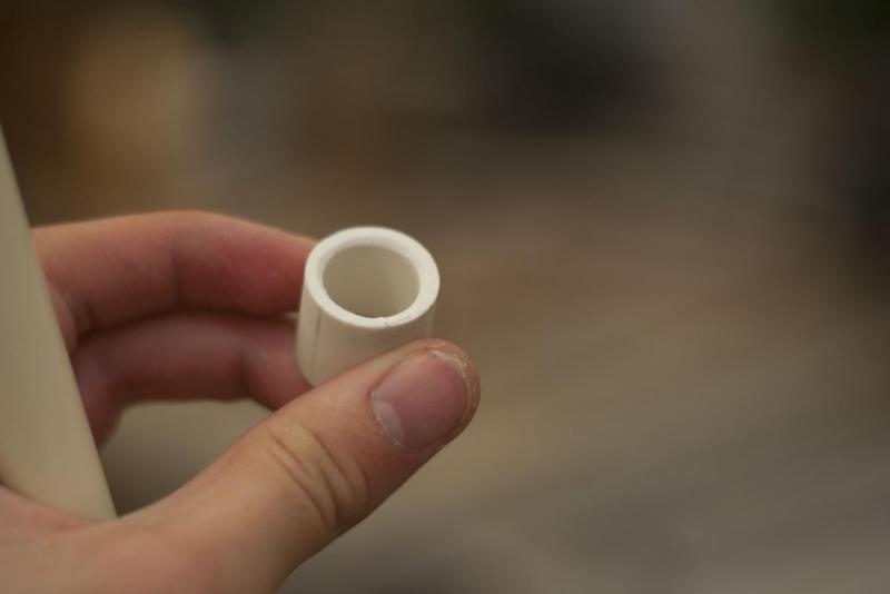
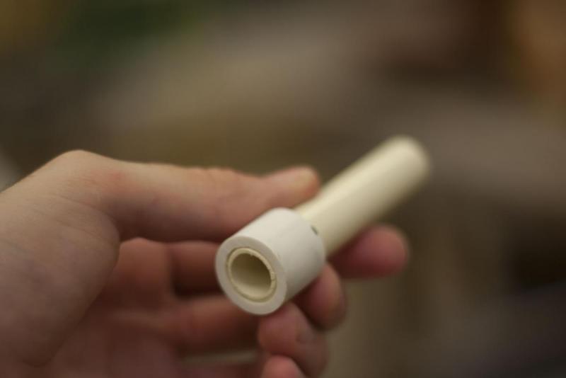
Cut the two small pieces out of the 1 ¼” PVC Wrap [3] after the holes are drilled and set them aside for later. They are used to create a spacer between the 1” PVC and the pump grip. I used a mitre saw for the 45 degree cuts at the ends of of the 1” and 1 ¼” PVC templates and a dremel on the channels for the pump grip. Again, use whatever is available to you.
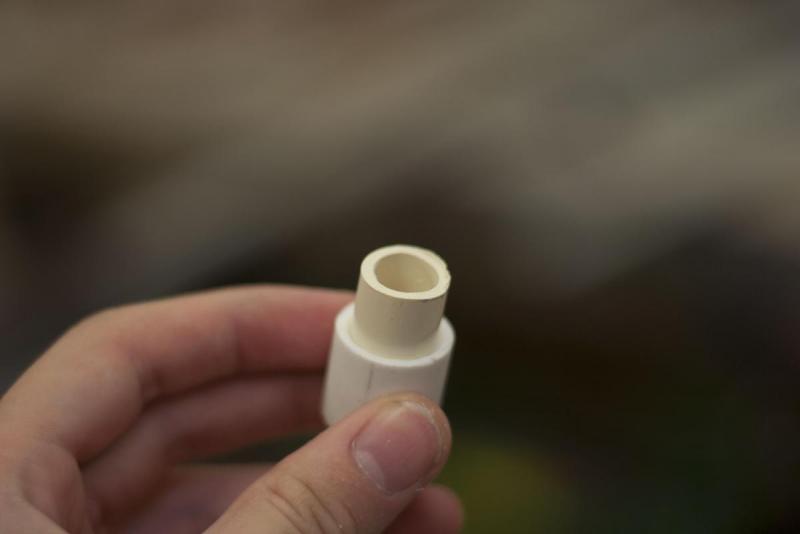
Take your 1” to ½” reducer bushing and put a few wraps of tape around it until it fits snug in the end of your 1 1/4 “ main body. Push it in until it’s flush with the main body, and drill two 7/64” holes through the holes already provided by your 1 ¼” PVC main body. Use Plumber’s Goop and apply it fully around the reducing bushing, and push it in. Wipe away any excess glue, and use your ¼” set screws to mechanically fasten it in place.
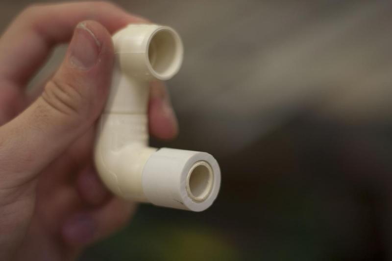
Take your two ½” CPVC elbows, and cut a section of CPVC to connect them together. It is necessary that the two elbows touch when together. When the you get the two elbows properly aligned, draw a line in sharpie to use for reference after glue is applied so you know they will be straight. Use PVC cement to make sure they stay together.
Next, cut a section of Sch 40 ½” PVC that will sit flush in your reducing bushing. Cut a length of ½” CPVC with a enough extra length for one of the elbows to attach to. Hammer that piece of CPVC into the PVC. Test fit your elbow. If it sticks out too much, trim the length of the exposed CPVC until the PVC and CPVC elbow touch. PVC cement the CPVC to the CPVC elbow, and push the entire assembly into your reducing bushing to test fit it. If all is correct, remove it for application later in the build.
CUTTING FLAT PLASTICS:
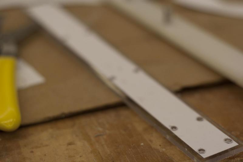
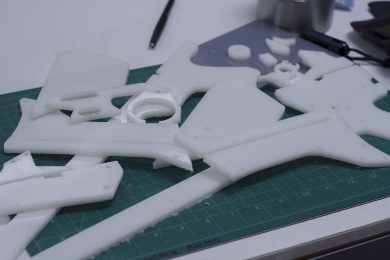
Next, use a glue stick to glue the other flat templates on your choice of Delrin or polycarbonate and drill out the holes where suggested on a drill press. Go slow with this as to not rip the template. On some of the bigger holes (⅝” and 9/16”) it might be a good idea to use an exacto knife and cut out that circle. That way if the bit does tear up the template, it’ll only tear the part of the paper template you plan to cut away anyway.
Also remember to cut the lower body cover from the ⅛” thick acrylic.
NOTE: do not cut out parts labeled “plungerhead3” and catch side at this point. They will be discussed later. Then cut out each template with your choice of cutting implement. Scroll saw and laser cutter obviously work best but a dremel and sand drum will work just fine too.
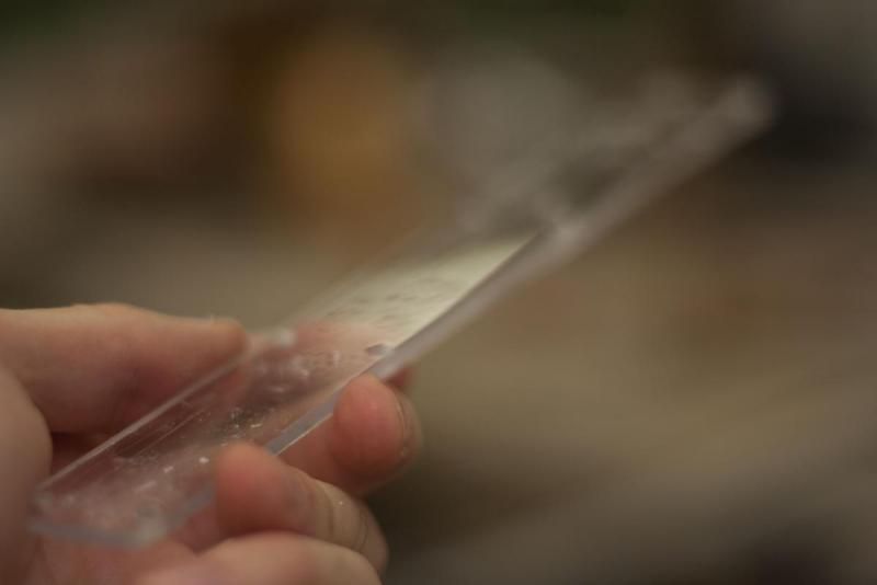
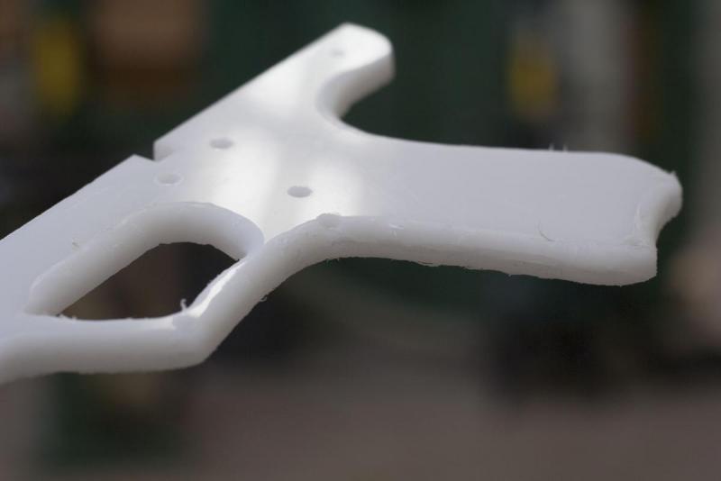
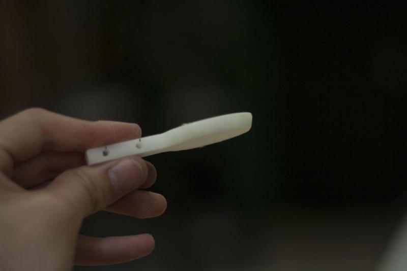
Once cut, this is a good time to file and sand the plastic smooth and bevel the outside of each handle, pump grip, and stock template.
The front, oval shaped mount will need to have the back half filed or sanded down to fit into the PVC main body at the proper angle.
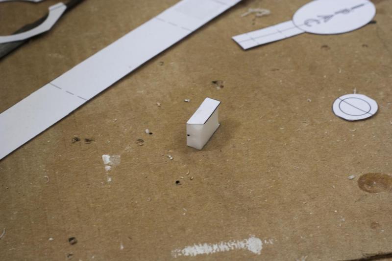
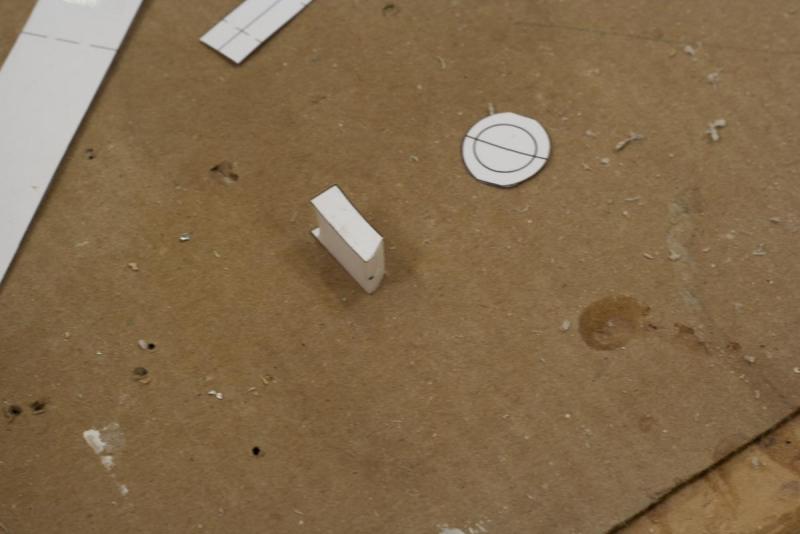
*For the catch piece, do not cut out the template labeled “catch side” in plastic. That is meant to be glued to the side of the catch lower once cut out and drilled through where the center line is labeled.
Once this is done, sand down the bottom of the catch lower where the catch side suggests in its shape.
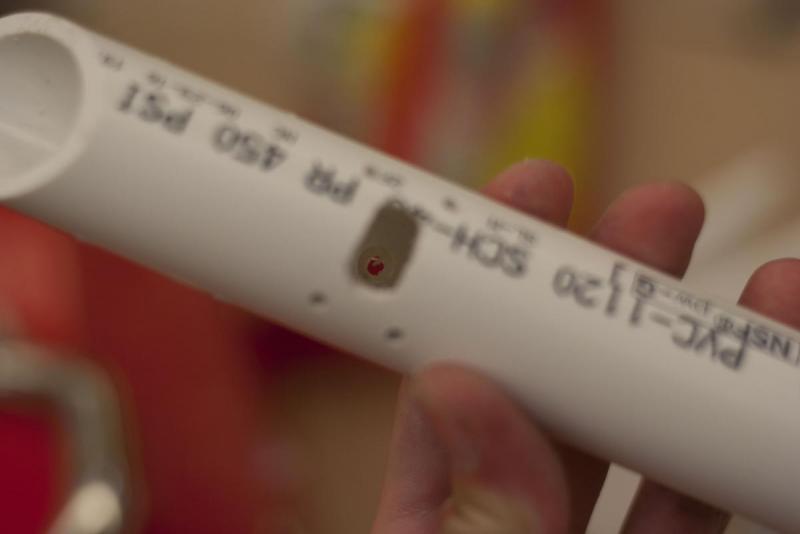
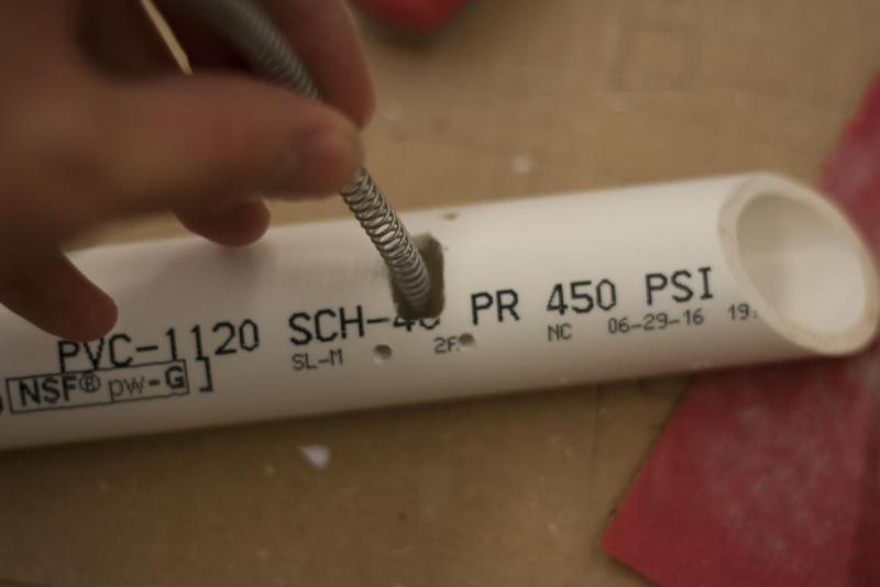
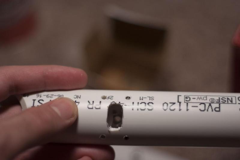
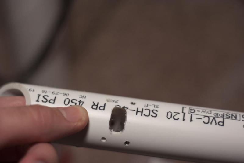
Take your 1” PVC Shuttle from before, and drill a ¼” hole on the inside wall opposite of the ½ rectangular hole you should have already cut. This should be drilled in the same hole the 7/64” hole was already drilled, shown on the PVC wrap template. NOTE: Only drill this ¼” hole half way through the PVC:
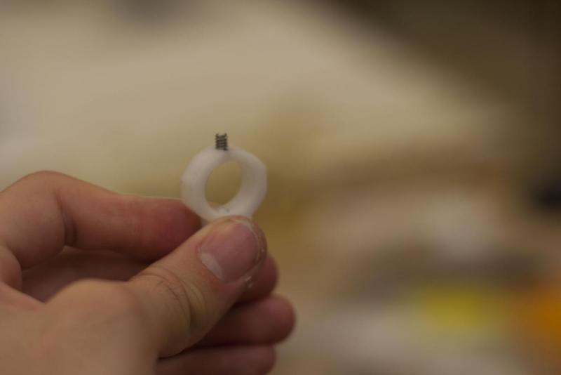
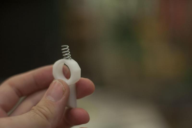
Put a ¼” allen screw at the top of your catch piece
Cut about a ½” of the K36 spring off to be used as the catch spring. The ¼” hole and the allen screw on the catch will work in tandem to make sure the spring stays in place later. Leave these to the side for finishing later.
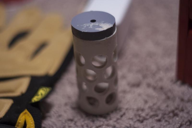
**For the Plunger Head 3 piece, also do not cut this out of your polycarbonate or delrin. This is meant to be cut out of the sheet of CPVC listed above. Once cut out, secure the wiffle tube cut from 1” PVC to one side of this piece with your PVC cement. Make sure you score the edges before hand.
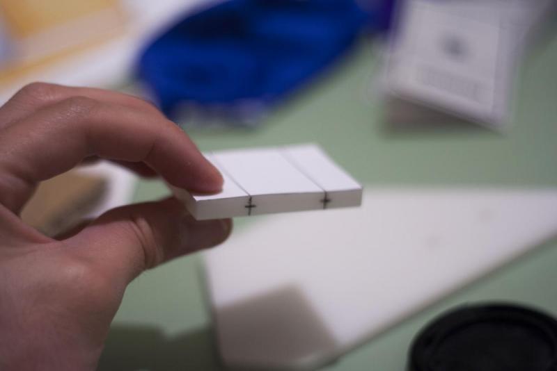
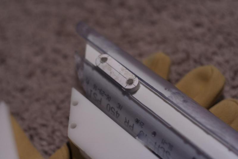
At this point, drill through your plastic at its center where the lines are suggested. I took a fine point sharpie and brought the lines over from the template, then made a center line shown below:
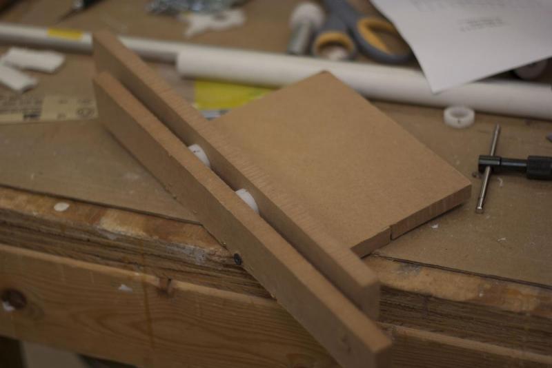
All holes must be made using a 7/64” drill bit unless told otherwise. I made a little jig for my drill press to make sure my holes were straight. Its just a piece of wood board with a sliver of wood screwed into the middle of it, and another free moving sliver of wood to go on the other side, held tight by a mechanical vice. Might be a good idea to make something similar.
Once all of the many holes in your plastic is drilled, use your tapping kit and cut threads in all of the 7/64” holes.
Now to cut and drill things without templates ![]()
Don’t worry, it’s not too much work.
PLUNGER ROD:
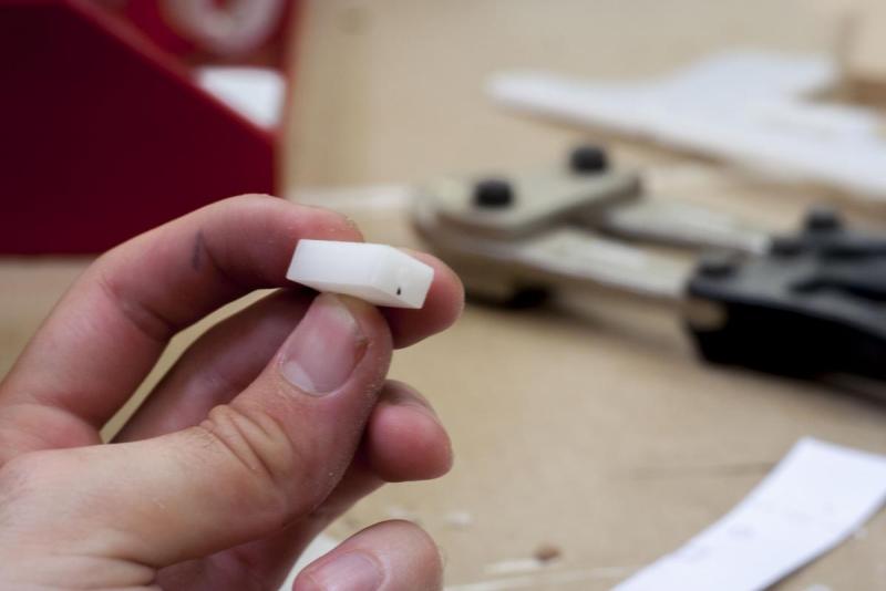
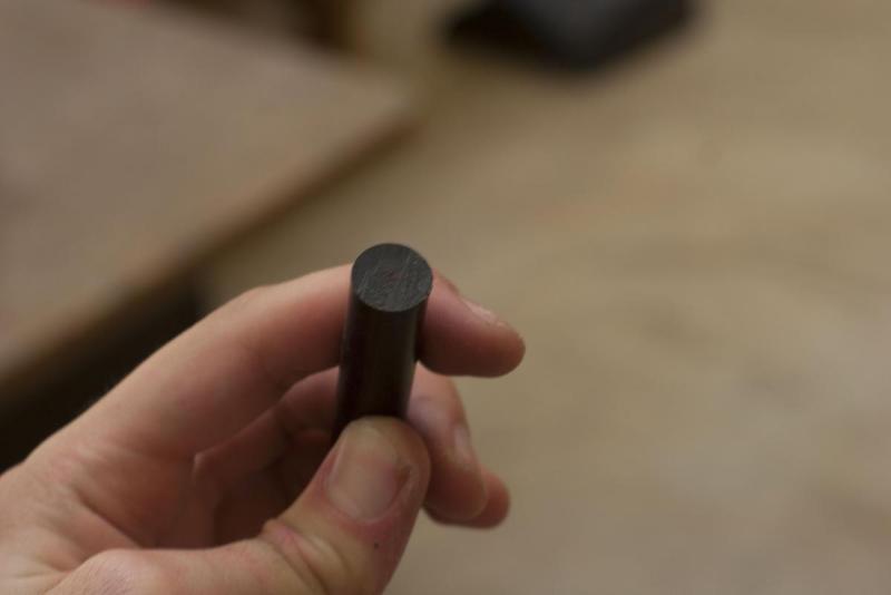
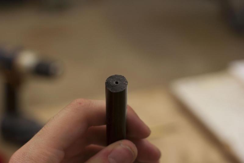
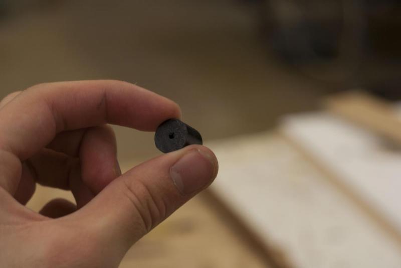
The plunger rod in total is 9 1/4 “ long, with two sections of ½” diameter Delrin rod at a length of 7 ½” and ½” respectively. Both sides of the 7 ½” section of delrin needs at least a ¾” deep hole with your 7/64” drill bit in the center of each end of the rod. The ½” section needs to be drilled the full way through. I cut a 9” section of delrin rod and drilled a ¾” long hole in one side and a 1 ¼” long hole on the other and cut a half inch segment off of that end of side with the deeper hole and trimmed down the excess until I had two sections of delrin at the proper size. Make sure to take your blade kerf into consideration when doing this It’s probably best to keep the delrin a little longer than needed and trim anything down after this process.
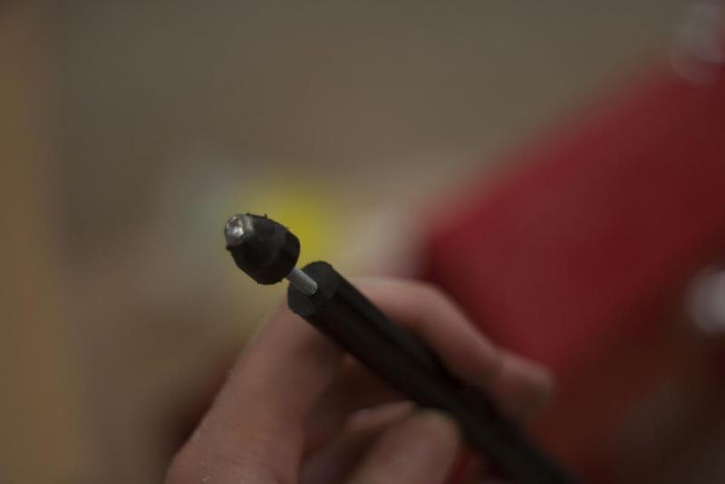
Tap the holes you drilled, and put the two segments of delrin onto a 1 ½” length screw with the unthreaded aluminum spacer in between. Take a file or sanding drum to the end of the smaller section of delrin rod and bevel that edge. This will be how our plunger enters the catch.
Take the Plungerhead one piece and score one side of it using sandpaper. Take the thick rubber gasket listed above, and super glue it to the surface.
On the other side, put the plungerhead 1, plungerhead 2 (with a skirt seal around it), plungerhead 3 (with wiffle tube attached) and the other end of the delrin rod together with the 1 ½” screw. It should look like this:
The plunger is done for now, and set it to the side.
ALUMINUM BAR:
This part is to connect the catch lifter and trigger together. Start by cutting the aluminum bar to 10 ¼”.
On the trigger side, drill 7/64” holes, 3/16” and ½” from the end of the aluminum. On the catch lifter side, drill 7/64” holes, ¼” and ½” from the end of the aluminum. Again, it’s best you make a pilot hole or make an indention with a nail before drilling. Tap these holes and use your ¼” screws to attach this to your trigger and catch lifter. Make sure it’s screwed into the same side of both parts. It should look like this:
Commentary:
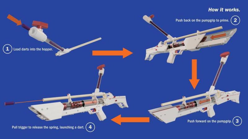
This will be how the slam fire on the blaster is engaged. The catch itself moves freely from the catch lifter, allowing the trigger to be pulled and the catch lifter engaged while the blaster is being primed. As long as you keep the trigger compressed while you are moving the catch to its standard position, it will run into the catch lifter, releasing the spring when its motion is complete. This was the biggest innovation of the blaster and took a large majority of time to plan out correctly. It needs a lot more work, but this is a good step in the direction of slam fire homemades and creating blasters with a much smaller profile than ever before.
ALUMINUM TUBE:
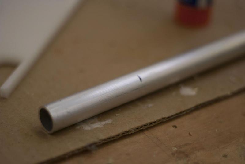
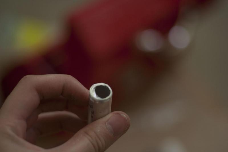
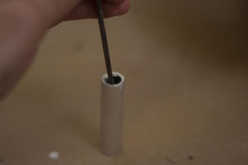
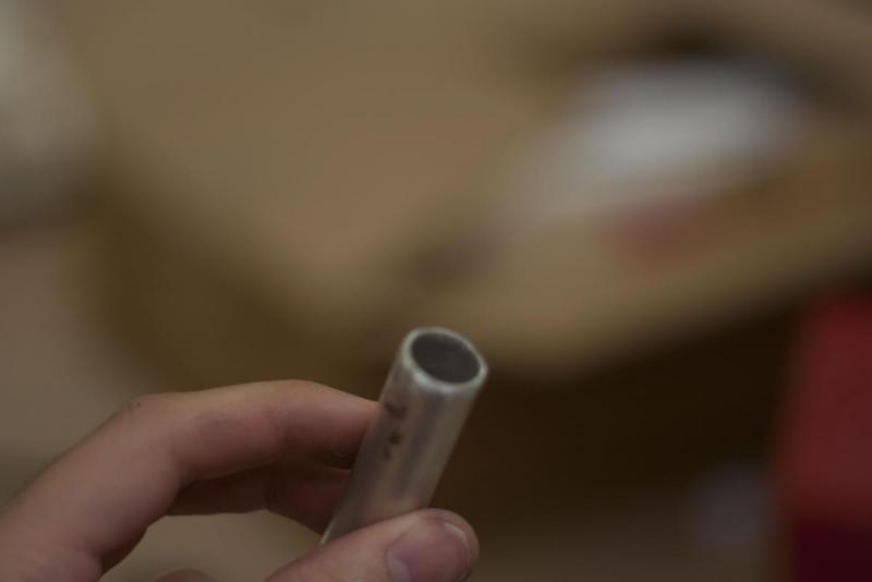
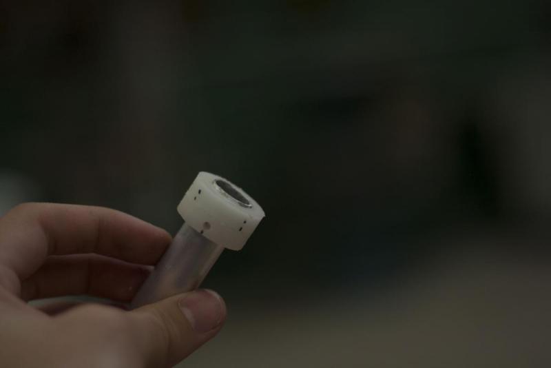
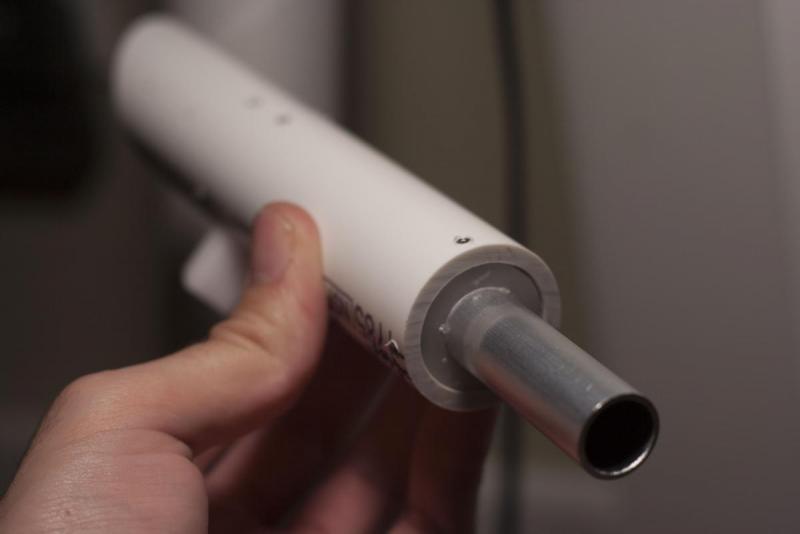
Cut a section of the ⅝” diameter aluminum to 3” with your dremel or proper metal cutting disk on your mitre saw, or on your bandsaw.
Make sure to bevel the edges with a file, then sandpaper. Watch your digits, this can be very sharp after it’s cut!
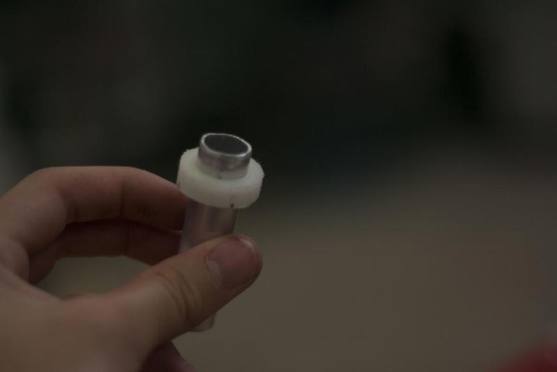
Once completed, hammer this into your spring rest piece. This will help guide your plunger rod into the catch area.
PUTTING IT TOGETHER:
All that’s left to do at this point is put the pieces together in the right places. I figure pictures are easier to follow than text for this part, so here's a ton of pictures showing how everything is put together properly. Make sure that the bottom of the pump grip and all parts attached inside the 1” PVC utilize Allen Screws at ¼” length, while the catch upper and lower and the main body to lower body mount are connected together with an Allen Screw at ½” length. If you choose to purchase them, four thumb screws are meant to connect the stock 1 to the stock 2 for ease of removal. Unless noted otherwise, all other parts are secured with your ¼” screws.
Put the blaster together in the order the pictures show:
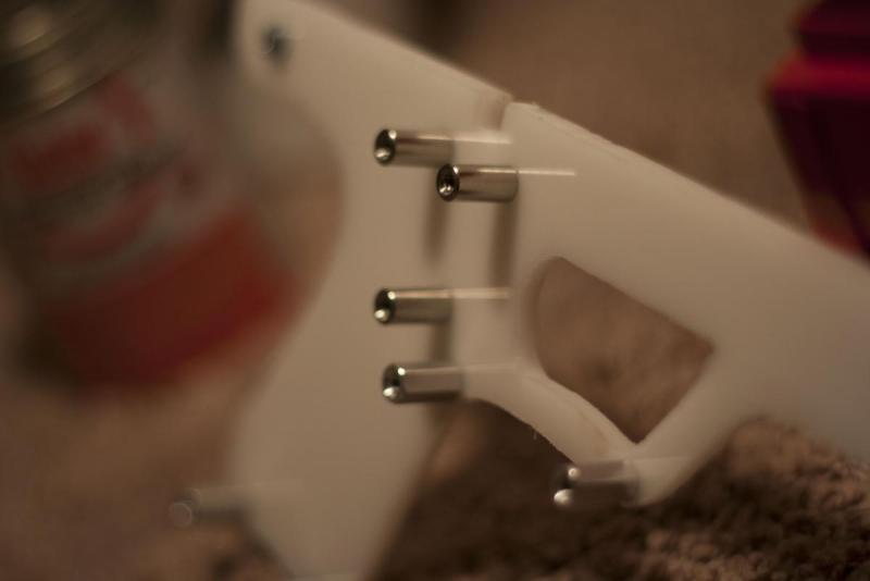
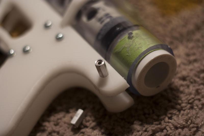
Take note that three of the ports behind the trigger use the round stainless steel standoffs.
Use your ¼” Allen screws to secure the trigger and catch lifter to the aluminum rod.
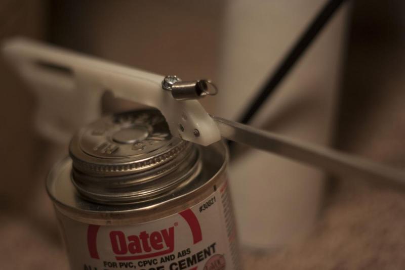
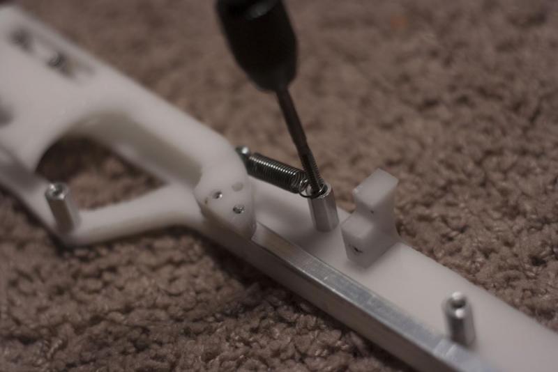
NOTE: I moved the extension spring to the top of the piece instead of on the side as the screw port would suggest. This HAS to be done due to lack of room in the lower body. I like this much better anyway.
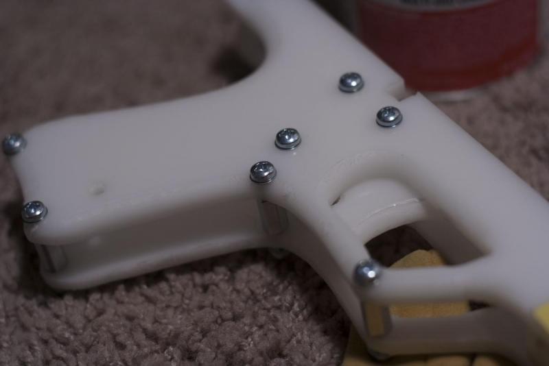
Secure the upper and lower body mount using ½” allen screws. Screw in the middle one until it is flush with the top of the template. We will use this later to screw into the upper body.
Use the ¼” Allen screws to screw in the first catch plate.
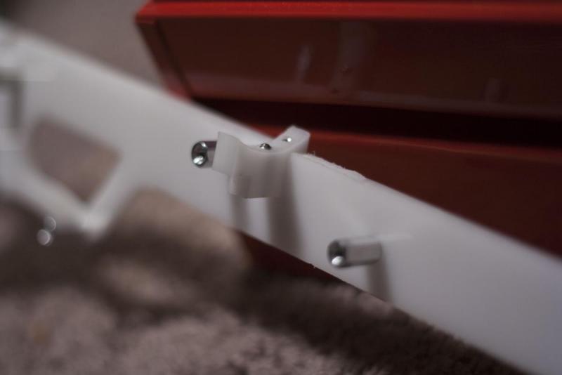
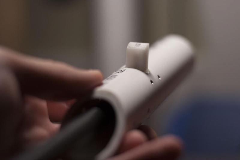
Put the catch spring into the channel drilled for it earlier. To put the catch in place, carefully guide it in on its back with the allen screw side entering first. When it’s hovering over the spring, start to turn it on its side, placing it right on top of the spring as shown in the picrues above.
Test the catch by screwing the catch lower in place using a ½” allen screw. I guided the plunger rod into the catch area as a point to press against as I screwed to catch lower in place. Remove it when secured, and depress the catch. It should a smooth and snappy motion. When satisfied, unscrew the catch lower for later.
Screw the spring guide in place on the other side with ¼” allen screws.
Time to screw the two sides of the lower body together. Notice how the extension spring is secured to the screw port shown.
Check the trigger mechanism at this point. It shouldn’t snag anything. Should also be smooth and snappy.
Next secure the pistol mount with ½” Allen screws.
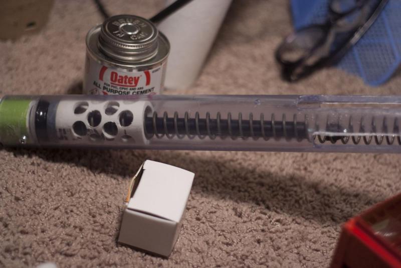
Slide the upper body through this mount. Then from the front, slide in your plunger rod, spring, and catch shuttle in that order.
Make sure to use Lithium grease or silicon grease before putting the plunger into the main body. Also, make sure it’s going the right way.
Align the upper body properly, and line up the hole that corresponds with the lowerbody/upper body mount. Take your allen wrench and screw the pieces together.
Now you can re-attach the catch lower to the catch upper. I again used something to hold the catch upper in place, and screwed the catch lower to it. I had to move the aluminum bar out of the lower body to do this.
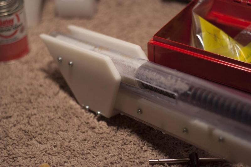
Take the lower body cover from earlier and secure it. Not only does it cover the bottom of the blaster, but it is crucial for the catch lifter to use its surface to press against and allow the strong catch spring on the catch to be depressed.
Put the pump grip together.
Cut down four 1 ½” screws for use on the pump grip.
Put the pump grip spacers in place on the catch shuttle, and secure the pump grip to them.
Finish it off by attaching the front mount to the front of the plaster.
At this point, attach the barrel section to your bushing. Put a CPVC barrel into the exposed CPVC elbow and align it into the front barrel mount.
STOCK:
I'll have to add more pictures later, but it is really easy to assemble. Put a 1/2" hex standoff on the two screws sticking out of the back of the pistol grip.
Secure the bottom of stock one to that point with another screw. For the upper screw port, remove the screw in the upper body securing the reducing bushing, and thread the screw through the port in the stock 1, and then back into the main body. A 1/2" screw may be too short, so cut down two 1 1/2" screws to work here. You may notice that the stock 1 doesn't sit flush on the main body. Put 4 #6 washers in between to make up that space. Then use the 2" hex standoffs to connect the two sides of stock 1 in all of the screw ports except for the two 7/64" holes in the back.
Separately, take the two sides of stock 2 and attach them together with the 1 1/2" hex standoffs in every screw port but the two 7/64" holes in the front.
The stock 2 should slide into stock 1. You can use 4, 1/2" set screws or optionally the 4 thumb screws to secure them together.
At this point, the blaster is finished. Test the trigger pull, and if it successfully lifts the catch. If all works like it's supposed to, when the blaster is primed, and the pump grip is pushed forward, it should fire. Slam fire should also work at this point too.
You can also attach a hopper at this point. You’ll notice that the pistol to main body mount doubles as a support for a PVC wye if it is attached.
TAKEAWAYS:
I’ve put a lot of work on the form of the blaster, and spent a lot of time working on the ins and outs of the whole of this project. But there are still some things that need work. Due to the time constraints of getting my portfolio done and making this writeup in time for the blaster competition, there are a few things I still have to improve: Like said before, I plan to work in a trigger lock, as well as adding a way to deprime the blaster without firing it. Because the slam-fire system I have set in place at this time, the catch can only be released at the end of its motion, meaning you either have to fire the blaster off or cover your finger over the barrel to safely deprime the compressed spring. In the future, I will work on that and look into 3D printing certain parts to improve its ergonomics and form. But for now, I am very happy with it, and I hope those who choose to build this are to and make their own customizations to the design. I had to get it out to make the blaster contest deadline, otherwise, I would have fine tuned a lot of things. Trust me, this thing works, it's just not up to my build standards. I will continue to update this thread with changes I inevitably make.
Edited by Spud Spudoni, 07 May 2020 - 05:49 PM.


