By the way the link to your spring doesn't work.
Thanks, if I click that link, it does'nt work, if I copy it and open a new window, it does work. Clearly Voodoo at work.
Try using this link https://www.assocspring.co.uk, and then entering D22790 as the search term on the company's front page. (box titled "search our site")
Close, but no. The spark would be created when the flint strikes the steel frizzen; the pan underneath holds the powder and catches the spark.
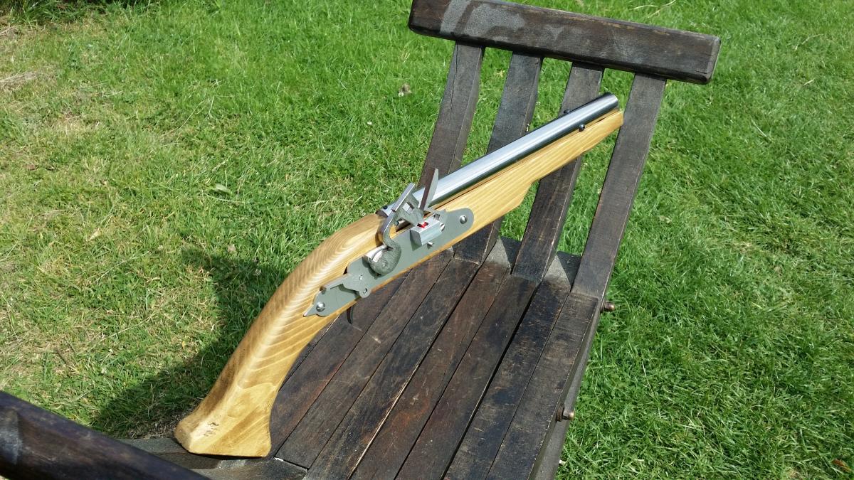
I don't see a flint, so I'm guessing it doesn't spark.
Indeed you are correct, no flint, no spark, instead it's adapted to fire off a toy cap instead . That way it makes a nice bang when fired.
That's awesome! I don't quite fully understand how it primes and fires though. I understand that it uses the ramrod to push back the piston, but does the hammer have to be cocked in order for the catch to work?
Also, does it spark when the hammer strikes the pan(I think thats what its called)?
The hammer does not have to be cocked, in order for the catch to work.
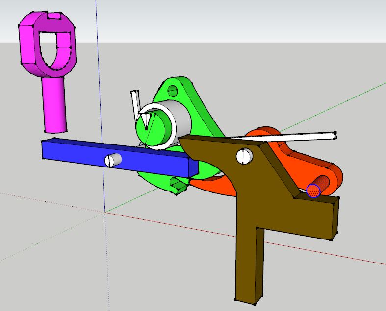
It's a little complicated to explain in words, so I'll post a CAD drawing of the internals, suffice to say, they are side by side mechanisms, in that the trigger activates both the hammer and the catch at the same time.
So in the picture the trigger (brown) is pulled, which lifts the sear (red) and pushes one end of the catch transfer bar (blue) down
The sear as it lifts disengages the tumbler (green) dropping the hammer,
at the same time the transfer bar rotates around its axle, and pushes the catch (purple) up.
So while the hammer position has not effect on the catch, this is how both are activated at (almost) the same time by the trigger.
Edited by Justin Andrews, 20 June 2017 - 09:11 AM.