Jump to content


Photo

Muzzle loading 17th Century Pistol


15 replies to this topic

#1 Justin Andrews

Justin Andrews

    Member

  • Members
  • 21 posts

Posted 15 June 2017 - 03:47 AM

*
POPULAR

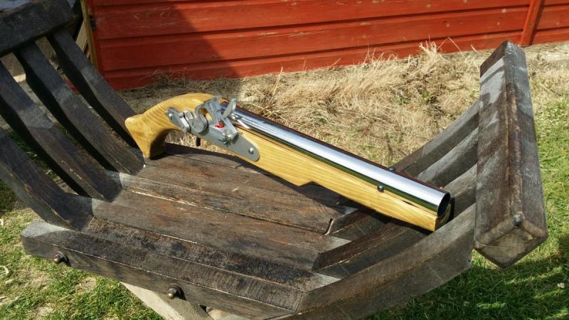
17th Century English Lock Cavalry Pistol (field test prototype).
LARP safe foam firing firelock.

Based on an existing English (or Doglock) pistol, this was a large pistol commonly used by cavalrymen.

The lock is a fully working copy of a flint lock, with both full and half cock positions, as well as a safety at half cock which makes it hard (though not impossible) to fire the pistol, in addition the external sear is movable and can be used to retain the cock.

Fires the same foam ball ammunition as the Larpquebus® with a range of around 9-10 meters, and well under the 1 joule limit (required in the UK to ensure the blaster does not fall under the legal category of lethally barrelled!)

Otherwise its the same general operation as the Muzzle loading Musket (Larpquebus) I posted here a while ago.


Attached Thumbnails

  • 1.jpg
  • 2.jpg
  • 3.jpg

  • 3

#2 Lasagna

Lasagna

    Member

  • Members
  • 45 posts

Posted 15 June 2017 - 08:19 AM

.


Edited by Lasagna, 17 June 2017 - 07:51 PM.

  • 0

#3 Justin Andrews

Justin Andrews

    Member

  • Members
  • 21 posts

Posted 15 June 2017 - 09:44 AM

Sweet. Still primes with ramrod right? Also, what is that barreling material?

Yep loads with a ram rod.
The barrel material is stainless steel, and also forms the compression chamber.

Piston uses a leather cup seal which is custom formed for the compression chamber.


Edited by Justin Andrews, 15 June 2017 - 09:45 AM.

  • 0

#4 Lasagna

Lasagna

    Member

  • Members
  • 45 posts

Posted 16 June 2017 - 08:57 AM

.


Edited by Lasagna, 17 June 2017 - 07:51 PM.

  • 0

#5 Justin Andrews

Justin Andrews

    Member

  • Members
  • 21 posts

Posted 17 June 2017 - 04:33 PM

*
POPULAR

I'm going to pretend you didn't say that. I will now go and cry about my inadequacy in the corner. JK but seriously, how did you do that? Does it seal well?

Very very well.
I was studying how high power air rifles work.
Although most modern air rifles use a sort of expensive silcone seal, back in our grandfathers day they used leather seals.

And it turns out that making leather seals is rather very easy.

You need natural undyed vegtan leather. This is very important as this leather can be molded by using warm, but not boiling, water. Hot tap warm I find work well enough.
The leather should be about 1.5mm to 2mm (sorry about metric measurements, I'm from the UK)

Next you need to make a mold. The sides of the mold should be the same internal diameter of your compression chamber (thats the Air rifle term for the air chamber)
Personally I just create one from a 12-15mm (or 1/2 inch) tall piece of the tube I use for the actual compression chamber.
Next you need the ram for the press, this should be around 3-4mm smaller in diameter than the ID of the compression chamber.

(don't worry I'll link to some sites about how to make these at the end of this post)

With the pieces of the mould made, you'll need a clamp, I find big woodworking hold down clamps work a treat.
Cut a piece of leather thats big enough to fit over the mold. Wet your piece of leather in the warm water until it more or less stops bubbling.
Place it rough side out, over the ring of the mold, and place the ram on top, transfer this to the clamp, and force the ram right into the mould.
Take a nice sharp knife, and trim the excess off.
Next leave it to dry for about a day. (I find overnight works)

Take it out the clamp, soak it in a couple of drops of oil (leather likes to be oiled in order to be supple, and you can get good oils for this) , and presto a cup seal that is pretty match for a rubber seal, but more interestingly is self lubricating.


This video most closely resembles how I make mine, except I don't use the screw method, and use woodworking clamps instead.

(some of these sites recommend using a socket as the ram, not tried that myself, as I made mine on my lathe, but I bet it would work)
http://www.pyramydai...er-piston-seal/
http://www.network54...er piston seals


Edited by Justin Andrews, 17 June 2017 - 04:34 PM.

  • 1

#6 FFNerfmodding

FFNerfmodding

    Member

  • Members
  • 12 posts

Posted 19 June 2017 - 12:03 AM

That is a sweet pistol. Would you mind making a video of it firing? How exactly does the propulsion mech work? I am curious.


  • 0

#7 Justin Andrews

Justin Andrews

    Member

  • Members
  • 21 posts

Posted 19 June 2017 - 06:51 AM

I must make a video of it firing :)
First I'll need to make a new one, as the one above is on loan to the chap who sells my muskets.

The mechanism is pretty simple, I use this spring https://www.assocspr...und-wire/D22790
with a *tiny* metal rainbow catch (I tried plastic, but the forces are way high and not much plastic to hold them, so it wears out too quickly)
(UK nerf builders, take note, the above company is *awesome* for springs)

As the compression chamber is the same diameter as the barrel, I have to keep the barrel very short, only 50mm.

To prime it, you use a ramrod down the barrel to push down and lock the pistol (this is intentional as these are replicas of black powder muzzle loading pistol)
then you pop the HIR into the barrel which has a 21mm choke in the barrel to hold the ball. The choke also acts as the end of the compression chamber, which is why you can see the heavy duty black screws in the barrel securing the choke from being displaced when the piston hits it.


Edited by Justin Andrews, 20 June 2017 - 05:00 AM.

  • 0

#8 Draconis

Draconis

    I am not Lord Draconical

  • Members
  • 2,712 posts

Posted 19 June 2017 - 10:59 AM

Wow, man, this is just as awesome as your last build.  Thanks for showing it to us!


  • 0
[15:51] <+Noodle> titties
[15:51] <+Rhadamanthys> titties
[15:51] <+jakejagan> titties
[15:51] <+Lucian> boobs
[15:51] <+Gears> titties
[15:51] <@Draconis> Titties.
[15:52] <+Noodle> why is this so hard?

#9 GensoNerf

GensoNerf

    Member

  • Members
  • 20 posts

Posted 19 June 2017 - 05:38 PM

That's awesome!  I don't quite fully understand how it primes and fires though.  I understand that it uses the ramrod to push back the piston, but does the hammer have to be cocked in order for the catch to work?  


Also, does it spark when the hammer strikes the pan(I think thats what its called)?


Edited by GensoNerf, 19 June 2017 - 05:39 PM.

  • 0

#10 jwasko

jwasko

    PowerBeard

  • Moderators
  • 1,021 posts

Posted 19 June 2017 - 09:24 PM

That's awesome!  I don't quite fully understand how it primes and fires though.  I understand that it uses the ramrod to push back the piston, but does the hammer have to be cocked in order for the catch to work?  


Also, does it spark when the hammer strikes the pan(I think thats what its called)?

Close, but no. The spark would be created when the flint strikes the steel frizzen; the pan underneath holds the powder and catches the spark.
 I don't see a flint, so I'm guessing it doesn't spark.


I really like your stuff, Justin. Thanks for sharing the info on leather piston seals. A long time ago I tried making one, but went about it way differently (read: wrong).


By the way the link to your spring doesn't work.


Edited by jwasko, 19 June 2017 - 09:25 PM.

  • 0

-Jwasko, STILL Sole Surviving member of Steel City Nerf and Sober Sister of the Sex Dwarves
We NERF ON all day, and FUCK OFF all night


#11 Justin Andrews

Justin Andrews

    Member

  • Members
  • 21 posts

Posted 20 June 2017 - 05:27 AM

By the way the link to your spring doesn't work.


Thanks, if I click that link, it does'nt work, if I copy it and open a new window, it does work. Clearly Voodoo at work.
Try using this link https://www.assocspring.co.uk, and then entering D22790 as the search term on the company's front page. (box titled "search our site")


Close, but no. The spark would be created when the flint strikes the steel frizzen; the pan underneath holds the powder and catches the spark.

 I don't see a flint, so I'm guessing it doesn't spark.

Indeed you are correct, no flint, no spark, instead it's adapted to fire off a toy cap instead . That way it makes a nice bang when fired.


That's awesome!  I don't quite fully understand how it primes and fires though.  I understand that it uses the ramrod to push back the piston, but does the hammer have to be cocked in order for the catch to work?  


Also, does it spark when the hammer strikes the pan(I think thats what its called)?

The hammer does not have to be cocked, in order for the catch to work. 
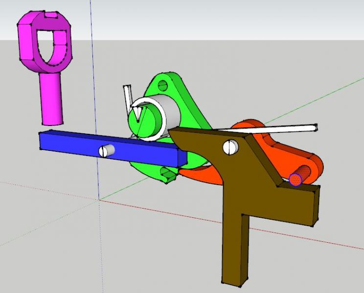
It's a little complicated to explain in words, so I'll post a CAD drawing of the internals, suffice to say, they are side by side mechanisms, in that the trigger activates both the hammer and the catch at the same time.

So in the picture the trigger (brown) is pulled, which lifts the sear (red) and pushes one end of the catch transfer bar (blue) down
The sear as it lifts disengages the tumbler (green) dropping the hammer,

at the same time the transfer bar rotates around its axle, and pushes the catch (purple) up.

So while the hammer position has not effect on the catch, this is how both are activated at (almost) the same time by the trigger.
 

Attached Thumbnails

  • lock.JPG

Edited by Justin Andrews, 20 June 2017 - 09:11 AM.

  • 0

#12 GensoNerf

GensoNerf

    Member

  • Members
  • 20 posts

Posted 20 June 2017 - 08:33 PM

Close, but no. The spark would be created when the flint strikes the steel frizzen; the pan underneath holds the powder and catches the spark.
 I don't see a flint, so I'm guessing it doesn't spark.

Oh, ok, thanks.


Indeed you are correct, no flint, no spark, instead it's adapted to fire off a toy cap instead . That way it makes a nice bang when fired.

Ah, would that be the red dot under the hammer?


The hammer does not have to be cocked, in order for the catch to work. 

It's a little complicated to explain in words, so I'll post a CAD drawing of the internals, suffice to say, they are side by side mechanisms, in that the trigger activates both the hammer and the catch at the same time.

So in the picture the trigger (brown) is pulled, which lifts the sear (red) and pushes one end of the catch transfer bar (blue) down
The sear as it lifts disengages the tumbler (green) dropping the hammer,

at the same time the transfer bar rotates around its axle, and pushes the catch (purple) up.

So while the hammer position has not effect on the catch, this is how both are activated at (almost) the same time by the trigger.

I see, thank you very much.  Is it possible to make them actuate at the same time, or would that be too much work for too little reward?


  • 0

#13 Justin Andrews

Justin Andrews

    Member

  • Members
  • 21 posts

Posted 21 June 2017 - 04:40 AM


Ah, would that be the red dot under the hammer?


Correct! :)
 

I see, thank you very much.  Is it possible to make them actuate at the same time, or would that be too much work for too little reward?


I tune the catch screw so as to get them to actuate pretty much at the same time, one of my ideas for the catch screw is to not use a single screw but to use two parts. The first part is a long 1/2 inch long grub screw, the second part is a brass hexagonal stand off. The grub screw is screwed into the catch itself, and the stand off into the other end of the grub screw. You can then alter the length of the catch screw by turning the stand off. This in effect alters the point at where the catch releases in relation to the pull of the trigger. Use a bit of threadlock paste to stop the brass stand off turning to easily.

A nylon stand off would probably work better than a brass one (as it would be harder to rotate) that's not something I've tested yet. It's something I keep meaning to drop into some dead space in the next batch of laser 3d printed parts (dead space in laser printing is usually free, so I usually fill it with something)


Edited by Justin Andrews, 21 June 2017 - 04:41 AM.

  • 0

#14 GensoNerf

GensoNerf

    Member

  • Members
  • 20 posts

Posted 21 June 2017 - 06:21 PM

I tune the catch screw so as to get them to actuate pretty much at the same time, one of my ideas for the catch screw is to not use a single screw but to use two parts. The first part is a long 1/2 inch long grub screw, the second part is a brass hexagonal stand off. The grub screw is screwed into the catch itself, and the stand off into the other end of the grub screw. You can then alter the length of the catch screw by turning the stand off. This in effect alters the point at where the catch releases in relation to the pull of the trigger. Use a bit of threadlock paste to stop the brass stand off turning to easily.

A nylon stand off would probably work better than a brass one (as it would be harder to rotate) that's not something I've tested yet. It's something I keep meaning to drop into some dead space in the next batch of laser 3d printed parts (dead space in laser printing is usually free, so I usually fill it with something)


Ok, thats really cool, I don't get what you mean by dead space in laser printing is usually free though.


  • 0

#15 jwasko

jwasko

    PowerBeard

  • Moderators
  • 1,021 posts

Posted 21 June 2017 - 08:09 PM

Try using this link https://www.assocspring.co.uk, and then entering D22790 as the search term on the company's front page. (box titled "search our site")

That worked, thanks
 
These are the stats:
Outer Diameter (Do) (mm) ...22.00
Wire Diameter (d) (mm) ...2.01
Free Length (L) (mm) ...199.9
Solid Height, Approx (mm)... 40.9
Spring Rate (N/mm) ...0.9
Load Length (L1) (mm) ...55.6
Load at L1 (N) ...132.6
 
Fun fact: The OD and wire diameter are basically the same as a Mcmaster 9637k26 spring. It's only 8inches long ([k26] is 11in or ~280mm) but the spring rate syncs up with an 8inch length of [k26] as well.

The solid height of D22790 seems a bit shorter though. I think [k26] has 3.09 coils per inch; it seems your spring has more like 2.6 per inch or 1 per cm.

Edited by jwasko, 21 June 2017 - 08:12 PM.

  • 0

-Jwasko, STILL Sole Surviving member of Steel City Nerf and Sober Sister of the Sex Dwarves
We NERF ON all day, and FUCK OFF all night


#16 Justin Andrews

Justin Andrews

    Member

  • Members
  • 21 posts

Posted 22 June 2017 - 04:59 AM


Ok, thats really cool, I don't get what you mean by dead space in laser printing is usually free though.


When talking about SLS 3D printing, you normally pay by the Cubic Centimeter / inch, or for a portion of the machines space. So any voids in your print you are still paying for, if you can put another object in that space, you are essentially getting that part free (or more to the point, you are already paying for that space so putting something in it is just sensible) The only condition is you need to get the part out, so it cannot be an enclosed void. 
 

That worked, thanks
 
These are the stats:
Outer Diameter (Do) (mm) ...22.00
Wire Diameter (d) (mm) ...2.01
Free Length (L) (mm) ...199.9
Solid Height, Approx (mm)... 40.9
Spring Rate (N/mm) ...0.9
Load Length (L1) (mm) ...55.6
Load at L1 (N) ...132.6
 
Fun fact: The OD and wire diameter are basically the same as a Mcmaster 9637k26 spring. It's only 8inches long ([[[[k26]]]] is 11in or ~280mm) but the spring rate syncs up with an 8inch length of [[[[k26]]]] as well.

The solid height of D22790 seems a bit shorter though. I think [[[[k26]]]] has 3.09 coils per inch; it seems your spring has more like 2.6 per inch or 1 per cm.

There is a higher rated version, try entering D12790, and looking at the Load at L1, 160N variant.
I tried using this version in my first version of the barrel. It was a touch overrated for the internals I'd made. It shattered the (high tensile) screws holding the compression chamber together and I ended up firing out both the HIR ball AND the piston down the garden!

Is the [k26] more like this D12840 spring perhaps?
If so, thats quite interesting, as thats the spring I use in my Muskets.


Edited by Justin Andrews, 22 June 2017 - 05:11 AM.

  • 0


0 user(s) are reading this topic

0 members, 0 guests, 0 anonymous users