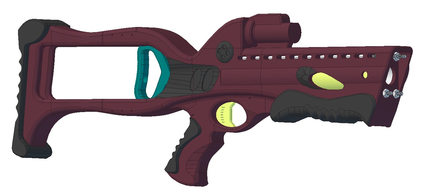
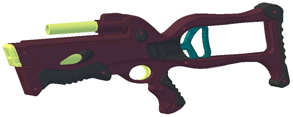
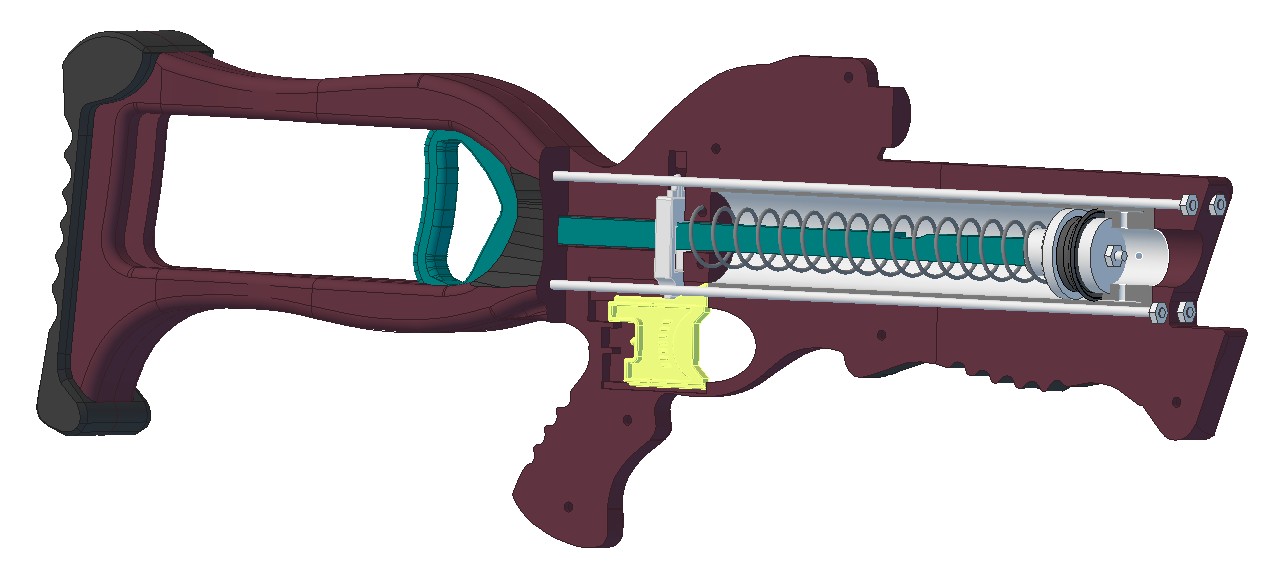
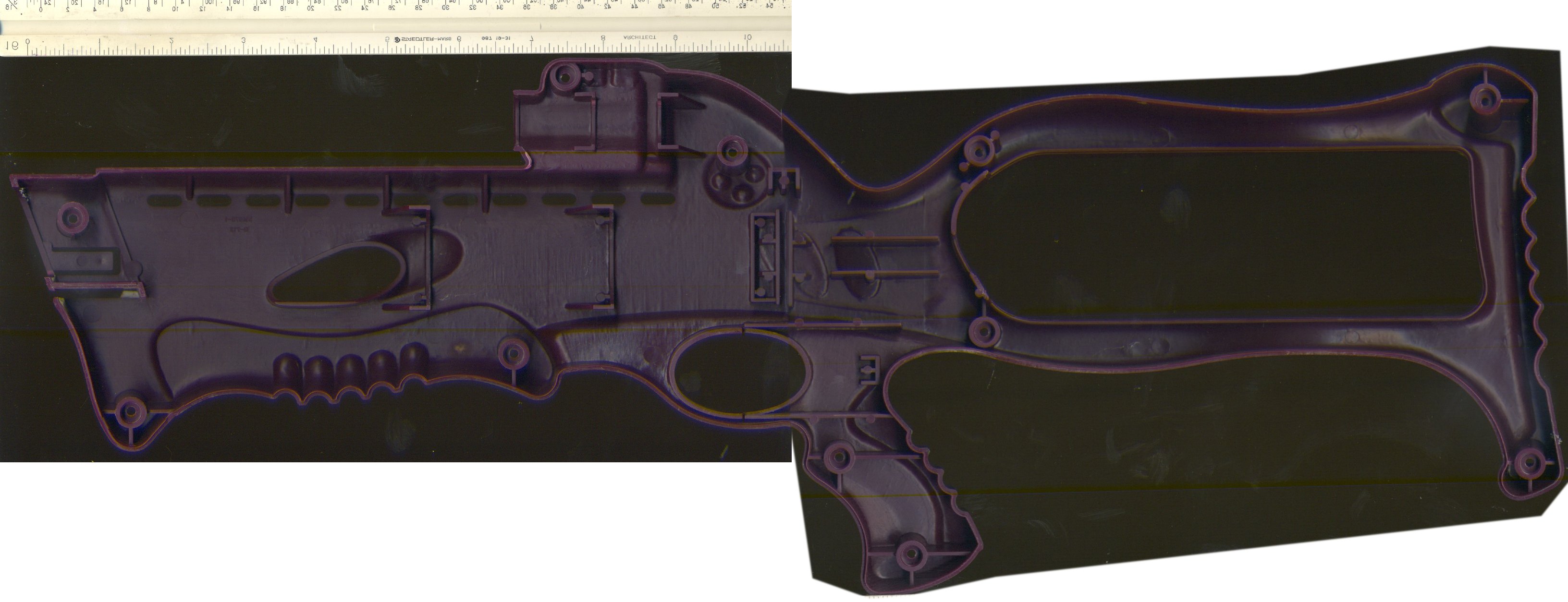
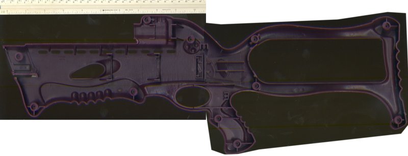
Alright, here's the non-stock version using custom parts and a larger ID plunger tube. I based this on the "Medium" configuration of Durendal since that is what will fit in the shell.
STEP 214 format: http://captainslug.c...ow95 Custom.zip (1.9mb)
STL format: http://captainslug.c... CustomSTL.zip (1.4mb)
Partslist
9637K26 1    Cut-to-Length Compression Spring, Spring-Tempered Steel, 11.0" Long,.844" OD, .08" Wire

90480A009 1  Low-Strength Steel Hex Nut Zinc-Plated, 8-32 Thread Size, pack of 100

99117A380 1  Steel Combination Slotted/Phillips Rounded Head Screw 8-32 Thread Size 12" Long, Pack of 5

94135K2 1    Type 302 SS Extension Spring, 1.0" Length, .250" OD, .029" Wire Diameter

9562K46 1    Stretch-Fit Shaft Seal for 1" Diameter Shaft

4880K314 1   Standard-Wall White PVC Pipe Fitting, 1 Pipe End Male x 1/2 Socket Female, Hex Bushing

1658T18 1    Highly Corrosion-Resistant 6063 Aluminum, Architectural, 1-1/2" OD, 0.065" Wall Thickness, 2 feet
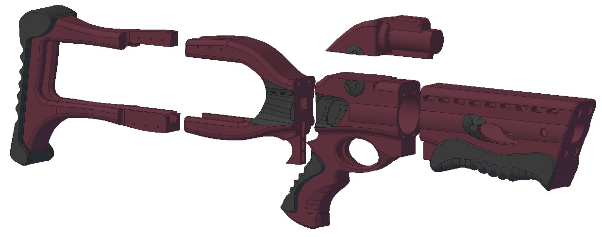
You will need 16ga finishing nails (or 1/16" diameter weld rod) and a strong adhesive to glue the two halves of the stock together. Finishing nails are also used to hold the extension springs for the trigger and catch inside the grip.
This uses a K26 or K25 spring cut down to 8-inches in length. Trying to use a full-length of either spring would require lengthening the stock slightly and changing the plunger handle a little. You can figure that out on your own if you want. The plunger tube material needs to be cut to an 8-inch length.
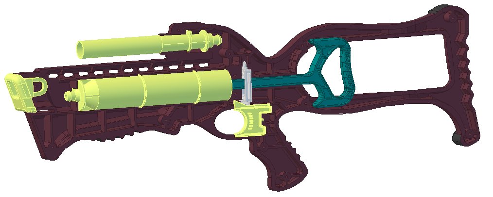
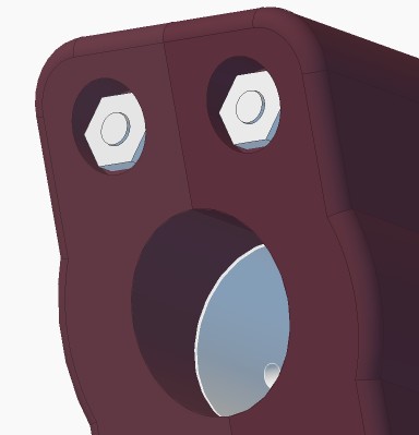
All of the components can be 3D-printed except for the plunger tube, springs, and hardware. Several of the functional parts could be substituted with polycarbonate parts. If desired, reinforcing the end of the plunger tube only requires adding a plate of 1/8" or 1/4" thick polycarbonate or aluminum.
The only part that I worry about in terms of durability is the plunger rod. The notch in it might wear out and I'm not sure how well the handle will hold up. So those will need to be tested.
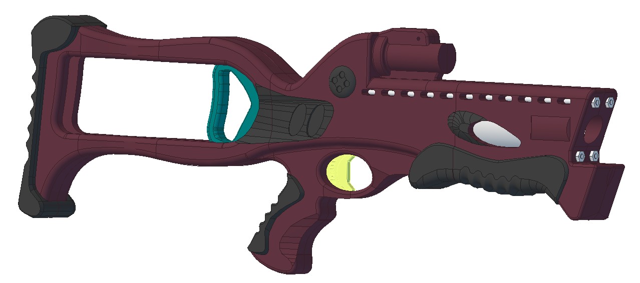
Now add on an accessory rail? 
You can put whatever kind of rail you want on top using screws. I won't judge.
The little critters of nature, they don't know that they're ugly. That's very funny, a fly marrying a bumble bee. I told you I'd shoot, but you didn't believe me. Why didn't you believe me?


