Well, there is a 3d printer lab at school. But, the printers don't print at actual size, and I can't remember the deviation. I think it is +0.02" for outside diameters and -0.02" for inside diameters. They're Printrbots, if that helps any.
On the Mk8-esque SNAP I'm building, the plunger head has a bunch of friction, enough to hold a [[k26]] back at full compression. Am I doing things correctly?
That sounds similar to my experience, here's a file you can try that seems to work so far that *should* have those tolerances built in:
 v3 Catch w Guide.stl 3.03MB
486 downloads
Then if you need I have this for a handle - scale up by 25.4 as apparently I messed up the export (I did something like 1.6mmx20% and the first one failed; this one is beefed up so maybe it'll be fine but upping the shells to be safe might be a good idea. This is the biggest file by far):
 DGrip V2.stl 3.14MB
489 downloads
And this trigger:
 v3 trigger.stl 1.04MB
482 downloads
And this plunger head, which I feel like I've shared before:
 MK10_PH.stl 1.08MB
441 downloads
These files are preliminary - I've gotten them all to work but have made modifications since my first handle sheared off. For all these files try 4 shells (1.6mm) and 20% infill at .25mm layer height with 1.75 top/bottom (if you can, if not 0.2 mm and 1.6) If that breaks step it up to 100% or do more shells. Altogether you're talking 110 grams of filament and ~8 hours print time.
You'll need some #6x3/4" machine screws, a small spring (pen spring, I used one out of a $5 harbor freight set), a #6 washer, #8x1.5" machine screws and nuts, a two-way bolt like this one, a dash 216 oring (1/8" by 1-3/8" OD), a 1-2" wood screw, a 1-1/4" fender washer, a 1/2" rod, and a couple of barrel nuts and screws. I've found all that stuff at ACE, probably at HD/Lowes as well though the two way might be trickier. You can replace it with any method of joining two 1/2" rods with a small gap between them.
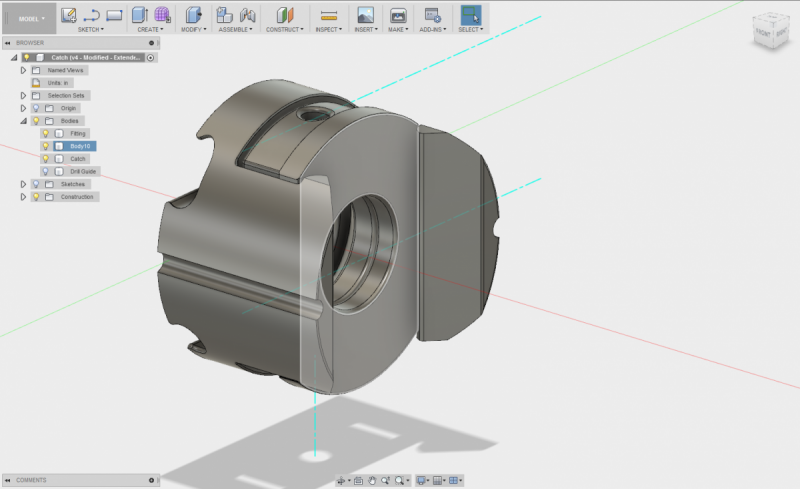
The large circle part is a template that goes over 1-1/4" PVC and allows you to accurately drill out the PVC for the catch. The part with legs is the frame, the one with the sloping hole and a small hole through it is the catch, the other one keeps the catch in place and may fit tight. You may need to sand that down a bit for it to fit easily and not break the frame.
To attach the handle, draw a straight line through the small hole from the circle template (Ideally use an architectural ruler, but I have used a corner between two smooth surfaces). This will be your bottom center line. Then position the handle along that line so that the large cutout is roughly centered on the small hole. Use the notches on the side of the handle by the holes to mark where to drill along the centerline. Drill these out for your barrel-nut screws (mine were 1/4"). Drill opposite those holes and do what you can to countersink them from the inside of the PVC. Your PT machining will be done once the screws fit, they don't need to be flush but it'll help.
You'll need to cut your 1/2" rod to fit your spring, then use the two way bolt to fix it together with a gap. Put the PH file with the oring on it on the appropriate end, run a wood screw into the rod with the fender washer. PH done.
To install the catch, put the catch pieces together (legs, catch, catch holder plate), run the #8 screws through the side holes on the PT, drop the catch in and orient it so it fits, and run the #6x3/4" with the washer and spring into the catch plate (Catch, PT wall, washer, spring, #6 head).
To install the handle, run a #6x3/4 through the side of the handle into and through the trigger, then put the barrel nuts in the holes in the handle. Run the 1/4" barrel nut screws into the handle.
Drop the PT into the blaster and through the catch assembly, add a 1"x1/2" bushing on the front (as with any pistol-type homemade) and you're done.
Let me know how it goes, I've needed a guinea pig for more extensive testing on this for a while.


