Jump to content


Photo

Preview: Rapidstrike Electronic Fire System

Electronics rapidstrike

16 replies to this topic

#1 Zack the Mack

Zack the Mack

    Member

  • Members
  • 360 posts

Posted 08 December 2016 - 01:11 AM

I've been working on an electronic Rapidstrike driver board, and I thought I'd show youse guyses as I build it up.


2016-12-14 02.31.58 scaled.jpg


Working title: The Hot Beef Injection.


HBI Driver 0-1 Screencap.png


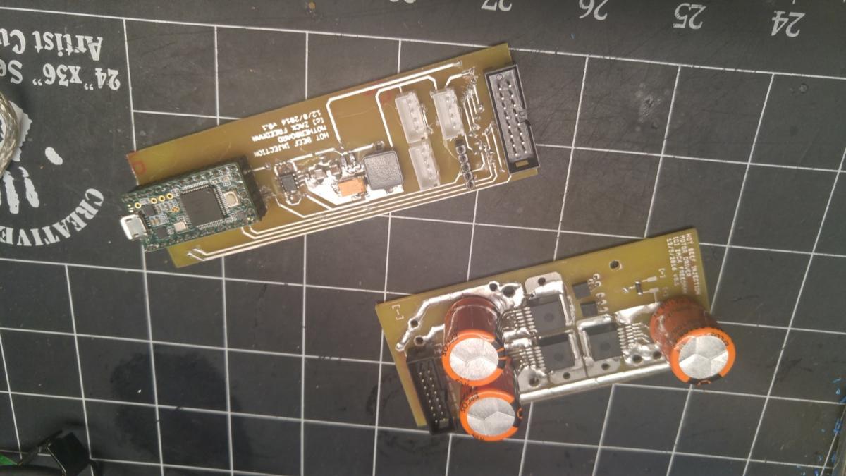
This first PCB is the motor driver. It replaces the Rapidstrike's front tactical rail and enables more sophisticated control than bare microswitches. Each driver is rated to 40A; a heatsink and temperature-controlled fan keep heat under control. This includes:

  • Full PWM - the system can ramp up the flywheels slowly, and keep them running at reduced "idling" speed
  • Dynamic braking - Prevents pusher overshoot, and lets me quickly halt the flywheels for "stealth mode"
  • Sensorless closed-loop control - I can tune the flywheel speeds to maximize energy transfer
  • Current sense - For fun. Also detects shorts and breaks for self-tests and safety.


HBI Motherboard 0-1 Screencap.png


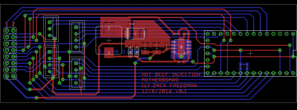
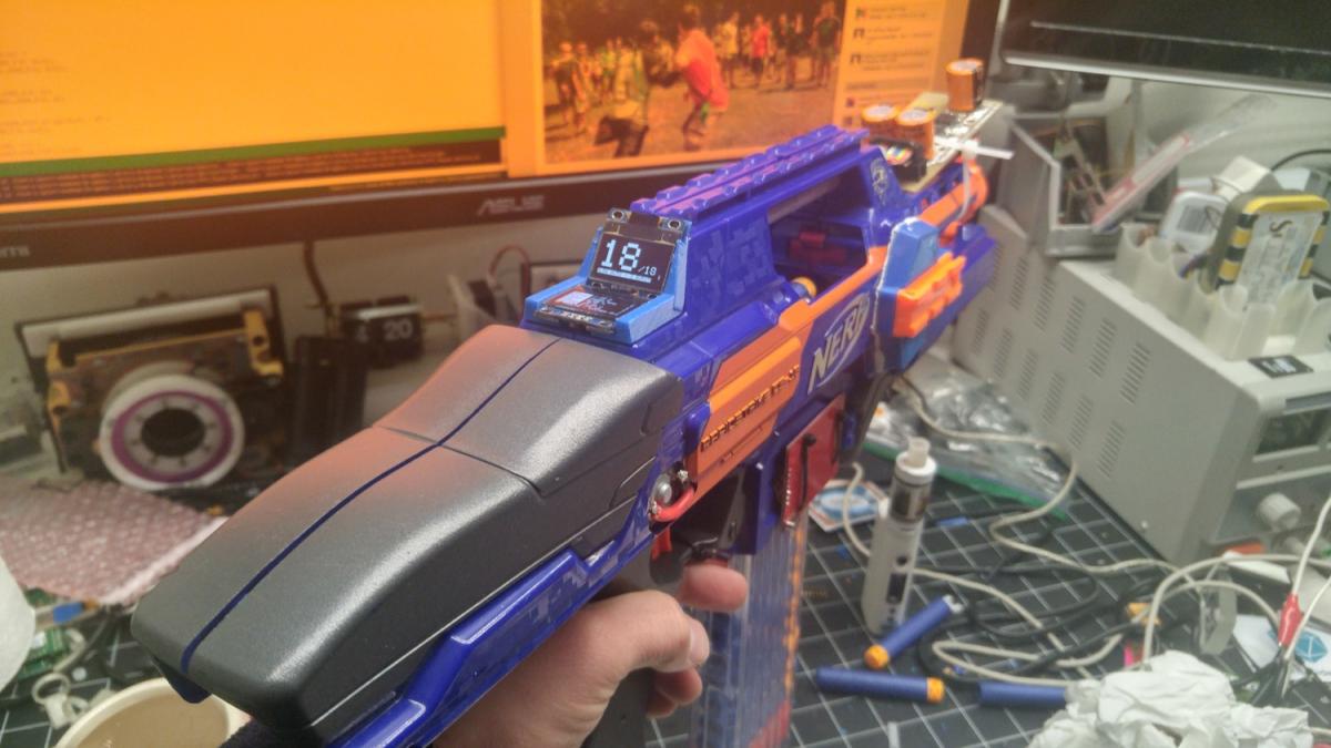
This PCB holds the Teensy microcontroller and has a 5V buck converter for efficient power. This slots into the empty space where the retractable stock used to be. The large connector on the end links this to the motor driver. The other sockets are for I/O:

  • Top left: Trigger and rev button inputs
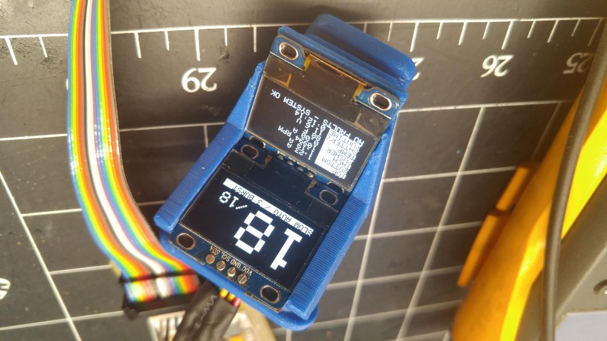
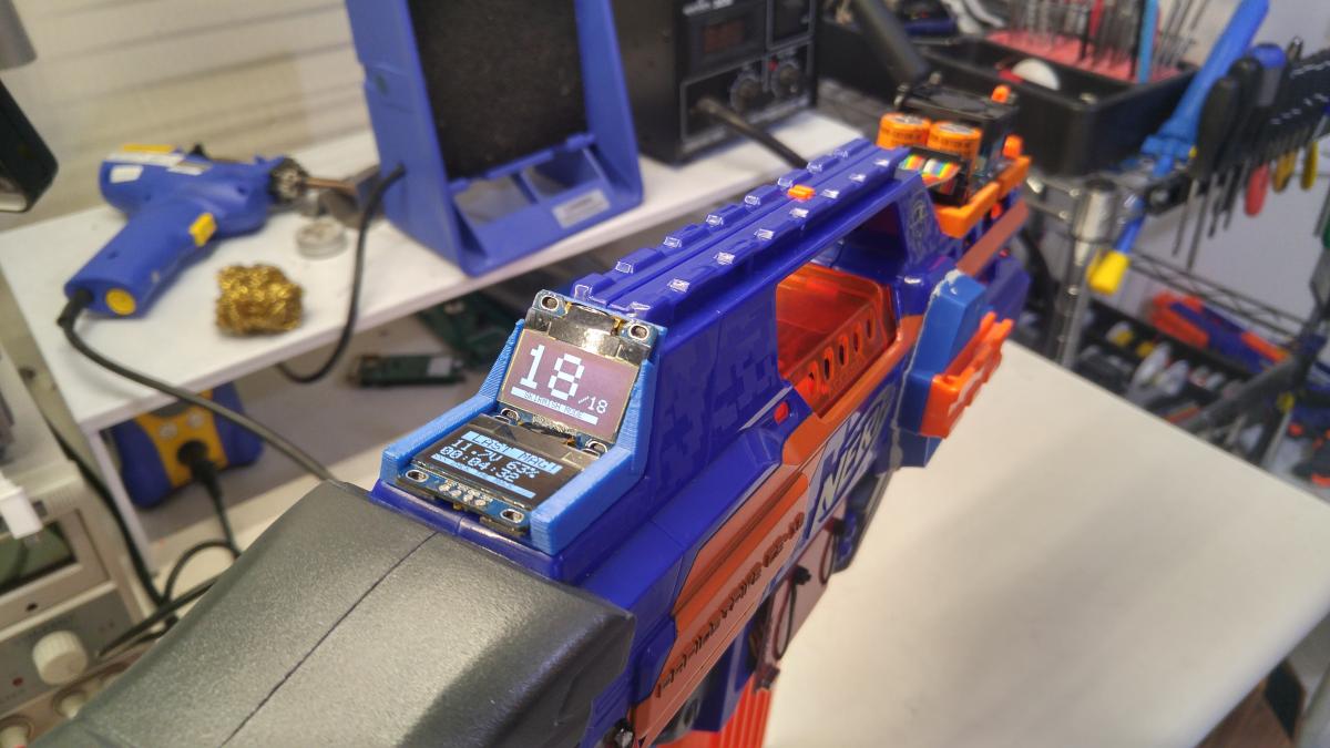
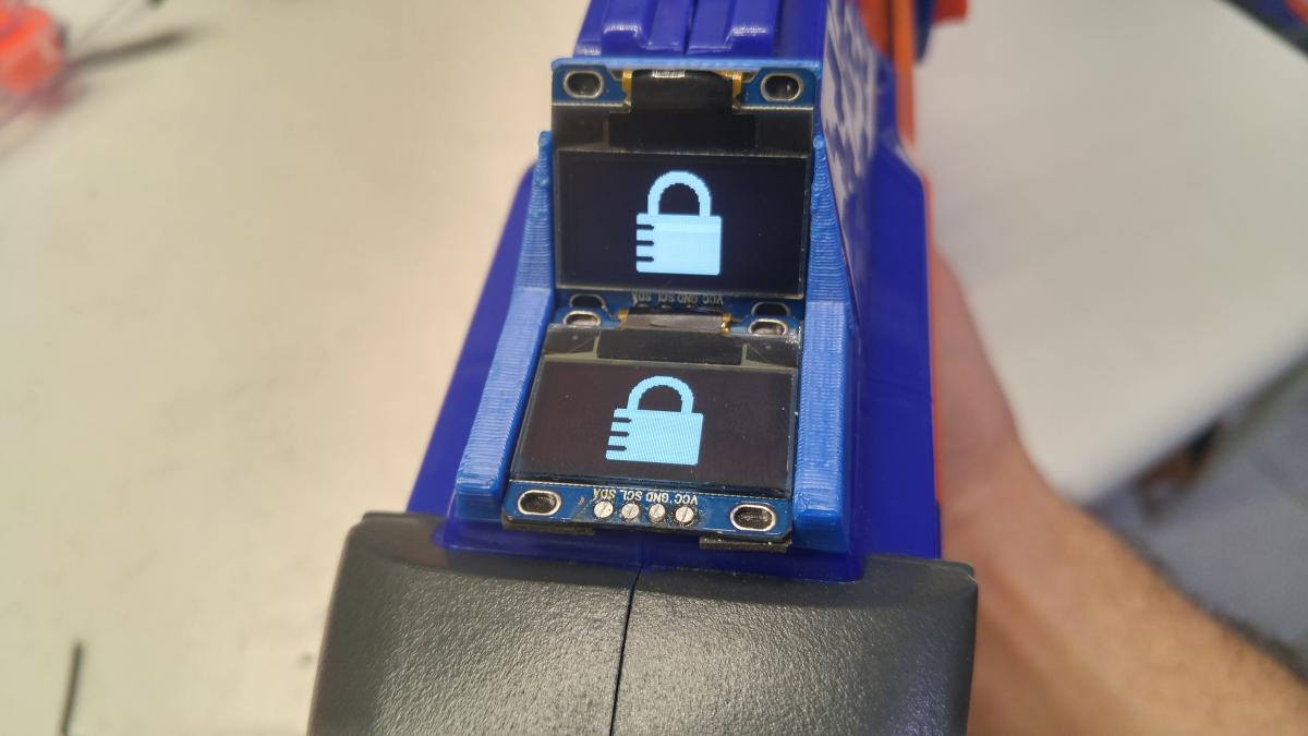
  • Bottom left: Two OLED displays connected with I2C
  • Top and bottom right: RFID board in mag well to detect magazine sizes
  • TBD: Stock pusher endstop switch and mag detect switch

I used a goofy layout, fat traces, and too many vias are because I'm etching these prototypes by hand. The copper clad should arrive soon, so I'll update the post when I etch them up.


Thanks for reading! This is an exciting project, and I hope to finish it by the 17th to bring to CPNO.


Edited by Zack the Mack, 14 December 2016 - 02:55 AM.

  • 0
Ask me questions about electronics, Arduino, and 3D printing

#2 NerfGeek416

NerfGeek416

    Member

  • Members
  • 151 posts

Posted 08 December 2016 - 12:09 PM

This looks awesome. I'm not as fluent electrically as I should be. Will this run brushless systems?
  • 0
 

#3 Zack the Mack

Zack the Mack

    Member

  • Members
  • 360 posts

Posted 08 December 2016 - 12:37 PM

This looks awesome. I'm not as fluent electrically as I should be. Will this run brushless systems?


Most brushless motors need a really complicated multi-phase driver. This fire system is intended for DC motors; it would need more complicated drive circuitry to handle brushless motors.


  • 0
Ask me questions about electronics, Arduino, and 3D printing

#4 Kingbob

Kingbob

    Member

  • Members
  • 133 posts

Posted 09 December 2016 - 10:28 PM

You could run brushless motors if you get a couple of small brushless controllers, and run the servo input on them from the Arduino.


  • 0

#5 Zack the Mack

Zack the Mack

    Member

  • Members
  • 360 posts

Posted 12 December 2016 - 12:12 AM


The boards are etched and populated! Testing is in progress. The motor controller board is shown without the heatsink or fan. I'll add them both after testing, when I know I don't need to rework anything.


Bonus! This 3D-printed adapter replaces the Rapidstrike's upper sling mount point with two OLED displays. The model for this part is attached for noncommercial use by any NerfHaven member in good standing.


EDIT: Not sure why the pictures came in upside-down, and I can't figure out how to flip them back over

Attached Thumbnails

  • 2016-12-12 13.25.31 scaled.jpg
  • 2016-12-11 23.56.35 scaled.jpg

Attached Files


Edited by Zack the Mack, 12 December 2016 - 12:13 AM.

  • 0
Ask me questions about electronics, Arduino, and 3D printing

#6 Zack the Mack

Zack the Mack

    Member

  • Members
  • 360 posts

Posted 12 December 2016 - 01:30 PM

2016-12-12 13.25.31.jpg


The displays work!


  • 0
Ask me questions about electronics, Arduino, and 3D printing

#7 myvenom

myvenom

    Member

  • Members
  • 11 posts

Posted 12 December 2016 - 01:58 PM

Ok this I way cooler than the rapidstrike I'm working on. Like Nerfgeek I'm not not this advanced yet. Nice job man.
  • 0

#8 Zack the Mack

Zack the Mack

    Member

  • Members
  • 360 posts

Posted 14 December 2016 - 03:04 AM

2016-12-14 02.31.58 scaled.jpg


Another quick status update: Electronics are fully assembled, tested, and confirmed functional. Unlike the previous pic, the display is actually showing dart count, and set its mag size by reading the RFID tag in the magazine.


The Hellcat pusher motor responds exceptionally well to active braking; the pusher homed on the first try after all 90 test shots.


I can't install the heatsink and fan until I build the motor driver enclosure (which is also why the motor driver is awkwardly zip-tied to the front of the blaster). Until then, I'm running the motors at half speed to prevent overheating. 


You can't see it from the picture, but the lower display is showing accurate temperature, battery voltage, and runtime. I need to figure out the conversions for the other metrics.


Once the motor driver enclosure is done, I can reassemble the blaster and do full-powered testing. I expect it to run like any Rapidstrike running triple Hellcats - fucking well.


Anyone have a pusher motor cover STL? I had to punch a hole in the shell to fit the 180 hellcat.


  • 0
Ask me questions about electronics, Arduino, and 3D printing

#9 Kingbob

Kingbob

    Member

  • Members
  • 133 posts

Posted 16 December 2016 - 08:50 AM

Interesting, how are you getting the motor rpm?


  • 0

#10 Zack the Mack

Zack the Mack

    Member

  • Members
  • 360 posts

Posted 16 December 2016 - 12:56 PM

Interesting, how are you getting the motor rpm?


It's a mock-up in these photos, but the wiring is there to do it for real.

I'm using sensorless back-EMF feedback to detect RPM. When a motor is freewheeling, it acts like a generator, and the voltage is proportional to the angular velocity of the shaft.

So, every once in a while, I freewheel the motor for a few microsexonds, sample the voltage, infer the speed, and adjust the drive. Of course, this isn't done while firing, because I don't want to decrease torque.

More information on this feedback system is available at https://www.precisio...m-from-back-emf .

It's worth noting that you need an H-bridge or half-H driver to use this method. A simple transistor follower, SPST relay, or switch leaves one end of the motor connected to voltage and makes it impossible to read the EMF.
  • 0
Ask me questions about electronics, Arduino, and 3D printing

#11 Zack the Mack

Zack the Mack

    Member

  • Members
  • 360 posts

Posted 22 December 2016 - 08:18 PM

This project is done!


Enjoy some preview pics while I make some videos and a proper write-up.


2016-12-22 16.50.25.jpg


Internals shot shows the wire routing, processor in back, and Artifact flywheel setup


2016-12-22 20.08.12.jpg


Except for the crazy motor driver, it looks almost like a stock Rapidstrike


2016-12-22 20.08.29.jpg


Close-up of the motor driver, with color-coordinated heatsink, caps, and mounting bracket


2016-12-22 20.07.41.jpg


Mag size and firing parameters are loaded from the RFID tag in the magazine. You can see the red RFID receiver on the mag well.


2016-12-22 20.08.42.jpg


Close-up of displays. Upper indicates that there's no mag installed. Bottom tracks my loadout, battery voltage, and game time


2016-12-22 20.08.59.jpg


When the blaster is locked, triggers and motor driver are disabled.


  • 0
Ask me questions about electronics, Arduino, and 3D printing

#12 DjOnslaught

DjOnslaught

    Member

  • Members
  • 350 posts

Posted 26 December 2016 - 08:14 PM

This project is done!
 
Enjoy some preview pics while I make some videos and a proper write-up.
 
2016-12-22 16.50.25.jpg
 
Internals shot shows the wire routing, processor in back, and Artifact flywheel setup
 
2016-12-22 20.08.12.jpg
 
Except for the crazy motor driver, it looks almost like a stock Rapidstrike
 
2016-12-22 20.08.29.jpg
 
Close-up of the motor driver, with color-coordinated heatsink, caps, and mounting bracket
 
2016-12-22 20.07.41.jpg
 
Mag size and firing parameters are loaded from the RFID tag in the magazine. You can see the red RFID receiver on the mag well.
 
2016-12-22 20.08.42.jpg
 
Close-up of displays. Upper indicates that there's no mag installed. Bottom tracks my loadout, battery voltage, and game time
 
2016-12-22 20.08.59.jpg
 
When the blaster is locked, triggers and motor driver are disabled.


Love the double display thing. I would like to do something like that if I get the right blaster for it
  • 0

#13 Nymx

Nymx

    Member

  • Members
  • 2 posts

Posted 03 January 2017 - 06:21 PM

What motor drivers are you using?


EDIT: I found some that should work: http://www.digikey.c...INCT-ND/4772019


Edited by Nymx, 03 January 2017 - 08:27 PM.

  • 0

#14 Zack the Mack

Zack the Mack

    Member

  • Members
  • 360 posts

Posted 04 January 2017 - 02:58 AM

What motor drivers are you using?


EDIT: I found some that should work: http://www.digikey.c...INCT-ND/4772019

Those are actually the motor drivers I used in this mod! They're ludicrously overspecified for Nerf motors, but they were very easy to build around.


  • 0
Ask me questions about electronics, Arduino, and 3D printing

#15 Nymx

Nymx

    Member

  • Members
  • 2 posts

Posted 06 January 2017 - 12:09 PM

You said you use the back-emf to determine rpm. That calculation requires the Kv of the motor. Is that value hard wired?
  • 0

#16 Zack the Mack

Zack the Mack

    Member

  • Members
  • 360 posts

Posted 06 January 2017 - 01:44 PM

That's determined largely by the characteristics of the magnets and should be specified on the motor datasheet. MTB's motor datasheets include it.

EDIT: Worth noting that in this prototype, the back EMF was readable but too noisy to be useful. A future version with better grounding and filtering should give me relevant readings.

Edited by Zack the Mack, 06 January 2017 - 01:46 PM.

  • 0
Ask me questions about electronics, Arduino, and 3D printing

#17 Nick Vanderplop

Nick Vanderplop

    Member

  • Members
  • 6 posts

Posted 06 January 2017 - 05:27 PM

...Shut up and take my money.


I LOVE the OLED display. Really sets it apart from anything else I've seen, which uses 7-segment displays. (which I despise for some reason)

Amazing. Just amazing. I wish I was that electrically inclined. But alas I am not.


  • 0

______|______\

\`````|```````


Also tagged with one or more of these keywords: Electronics, rapidstrike

0 user(s) are reading this topic

0 members, 0 guests, 0 anonymous users