

After seeing, for a couple of years, the hype, and of course this community's want for an ammo counter, what I wanted to do here is provide a comprehensive, yet easy and cheap step-by-step overview and tutorial on how to make one, for anyone to follow. I am an advocate of free knowledge, and after seeing the ridiculous prices of the seemingly monopolizing of ammo counters, I feel that members of this community should have the resources readily available to make their own, with the ability to add their own little kick and little features to make it unique.

Here's how it will work:
It's simple. When the trigger is pulled, count down 1 from the ammo. When a magazine is inserted, refill the ammo. A button can be used to toggle through the different magazine sizes: 5, 6, 10, 12, 15, 18, 22, 25, and 36. The last mode is counts up, starting from 0, which can be accessed from the toggling the magazine sizes. The magazine sizes will increment, with the press of the button, from 0, 5, 6, 12 … 36 and will not decrement, for the sake of simplicity.
A Little About Myself
I'm just another 16-year-old developer from San Francisco, and I make games. None of them are finished, and none of them will be. But I want to spread computer science, computer programming, to realms where I see are highly applicable. I am self-taught on hardware, so that will explain a lot on that aspect of it. Oh yea, and I modify NERF blasters.
All the photos I used will be available in this Imgur album.
Let's Get Started!
This will be demonstrated on a Stryfe, but of course, this basic recycled concept can be easily applied to any blaster. NO PROGRAMMING EXPERIENCE NECESSARY! In fact, no programming will be done. But you should know how to use a computer.
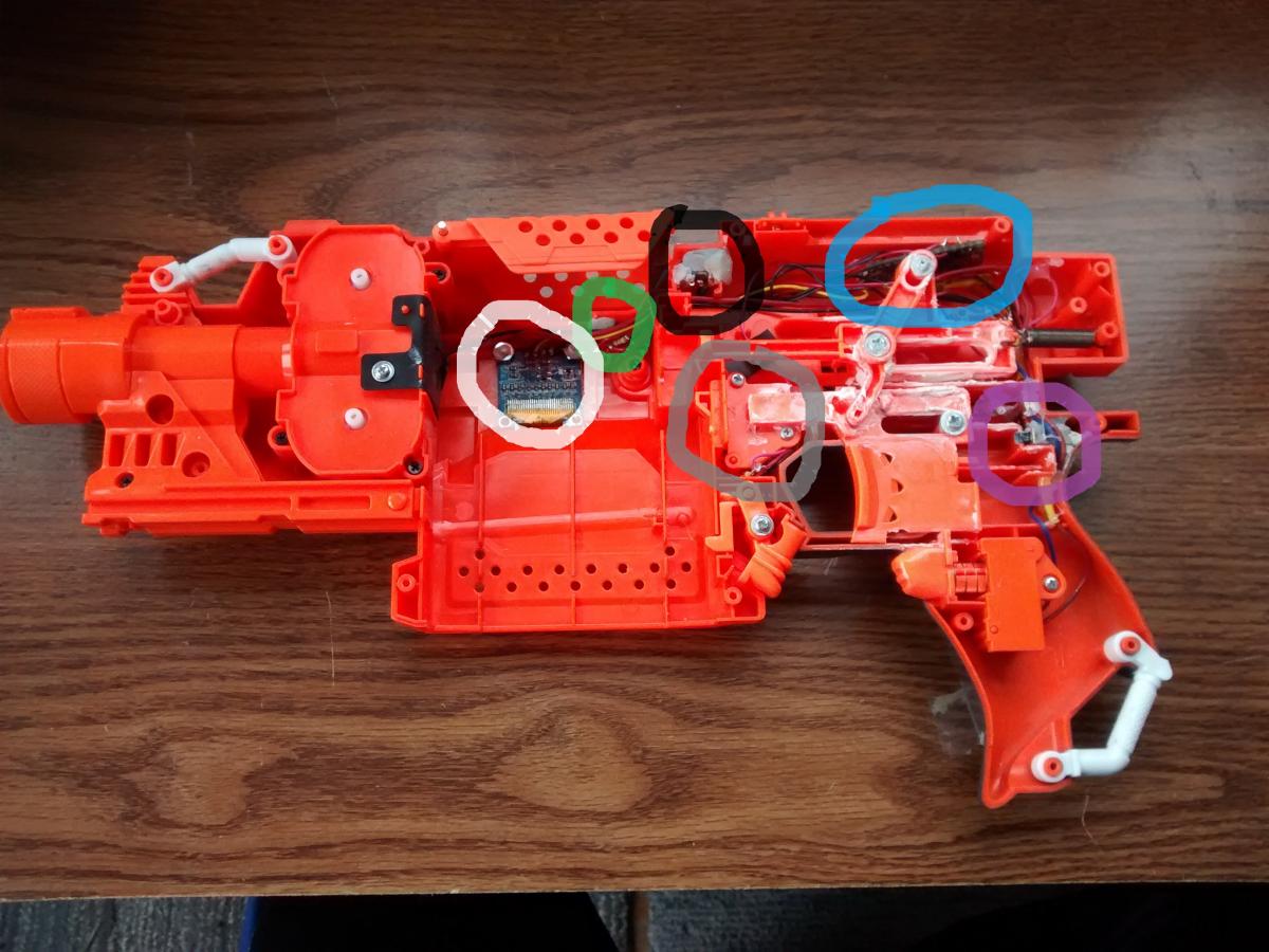
BLACK circle: The power switch of the ammo counter itself, not the entire blaster.
WHITE circle: The display, where the ammo will be visible to the user.
BLUE circle: The microcontroller, the brains of the counter.
GREY circle: The magazine lock, re-purposed to for magazine detection.
PURPLE circle: The jam door locked, re-purposed for trigger pull counting.
GREEN circle: The switch to toggle between the various magazine sizes.
With the recycled magazine lock, we can use it to send some useful information to the microcontroller: whether the magazine is inserted or not. Just like how it was as a magazine lock, when the switch is compressed, a magazine is inserted. When the switch is not compressed, there is no magazine inserted.
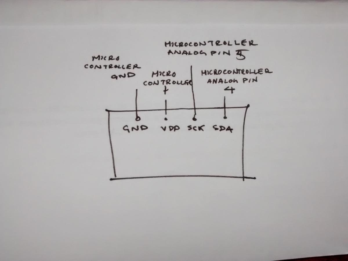
The circuit is incredibly simple as well (I don't really know how to make schematics):

Parts and Tools:
Tools:
-
Laptop/Desktop Computer (To program and upload code to the microcontroller)
-
Micro-USB charger (To upload code to the microcontroller)
-
Soldering Iron + Solder
-
Wire
-
Dremel/Rotary Tool (Cut slot in shell for display)
-
File/Sandpaper (Smooth clot in shell for display)
-
Standard tools for modifications: Screwdriver, wire cutters, pliers, etc
Here's what I used, and this tutorial will use these:
-
1x Stryfe - $20
-
1x Adafruit Pro Trinket (An Adafruit Trinket($7) can be used instead and still easily be able to follow this tutorial) - $10
-
1x Unbranded OLED Display - $3
-
3x 15k Ω Resistors (10k can be used) - 1¢
-
1x Rocker Switch - 5¢
-
1x Push button switch- 5¢
-
2x Nuts + Bolts (To secure display, more can be used to secure the microcontroller, but the ones I used were too big for the Adafruit Pro Trinket) - #4 - 40 x 3/8in - 10¢
-
.001x Epoxy Putty - 1¢
Total Cost: $33.34
Total Cost of counter: $13.34
A cheaper microcontroller can be used, including some Chinese Arduino knock off or this >$1 microcontroller (I'm still testing it) to knock the price down to $4.34, but other components may be required to get it working, including a linear 5v regulator.
1) Programming the Microcontroller
Let's first program the mircocontroller for before we start doing anything else. The rest of this will be demonstrated using the Adafruit Pro Trinket.
a. Download and install the Arduino Integrated Developer Environment (IDE) and its drivers. This process is a little different for using an Adafruit microcontroller, so follow these instructions. If you're on Linux, follow these instructions instead. If you already have the Arduino IDE installed, you can skip this step.
b. Download the source code for this project here. There should be a green button on the right labeled "Clone or Download". Click on it, and a drop down will appear. Then click on download ZIP. (Feel free to follow me and star my repositories). Unzip the folder you just downloaded.

c. You can delete the entire folder 'tests' from the code you just downloaded. It contains some stuff involving different parts of the project, including the buttons and starting up the display. Keep it if you just want to look at the code or are interested in learning its content.
d. Now you are going install the libraries from the source code downloaded. A library is basically code that other people wrote, but we can use it too. The libraries included will be used for the display. If you need help installing the library, follow the steps here, and scroll down to 'Manual Installation'. They will be exactly what I will be doing.
The libraries to use will be in the folder 'lib' in the source code you just downloaded, and it should contain 2 folders: 'Adafruit_SSD1306-master' and 'Adafruit-GFX-master'.
Make sure not to have a window of the Arduino IDE before doing this. Find the location of the Arduino folder. Mine is 'C:\Program Files (x86)\Arduino\'. Once located, open the the folder 'libraries'. Drag the 2 folders 'Adafruit_SSD1306-master' and 'Adafruit-GFX-master' from the folder 'lib' from the source code you downloaded. That's it! You're libraries should now be installed.
e. Everything for the microcontroller is basically done, now you just have to upload the code onto the microcontroller. If you're on windows, you have to install the appropriate drivers for Windows.
Once completed, you have to select your board, since there are so many Arduino and Arduino compatible boards. If you installed the Arduino IDE with the instructions above, you should have no problem doing this. If you already have already had the Arduino IDE installed and didn't follow the instructions above, import the Adafruit boards by navigating to Tools->Boards Manager and search 'Adafruit' into the search bar, and install the one titled 'Adafruit AVR Boards'.
Select the Pro Trinket 5V/16MHz (USB) board from the Tools->Board menu at the top. Next go into the Tools -> Programmer menu and select the USBtinyISP programmer.
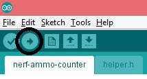
Select your port by following the instructions in the image below.

Now plug in the Adafruit Pro Trinket into your laptop using a micro-USB cable into the specific serial port. A green LED, indicating power, and a red pulsing LED, indicating that the Pro Trinket has entered bootloader, should turn on. Once the red pulsing light stops pulsing, press the only button on the Pro Trinket and wait for the red pulsing light to start back up. Once it turns back on, press the Upload button at the top left the Arduino IDE, as identified by the right pointing arrow and to the right of another button with a check mark in it. Some text should print in the message area, at the bottom of the window. When a message, "Done Uploading" appears, your code has been uploaded onto the Pro Trinket! You should see a red LED on.
You are now done with everything on the computer and The Pro Trinket is completely set up!
2) Shellwork
Now let’s get started with the blaster!
a. Open it up and take out the internals. Needless to say, store them somewhere so you don’t lose them, etc. Don’t throw out any parts! There is a good amount of reusing of parts in this. Be careful with the switches too, as they will be repurposed.
b. Remove all locks, replace the motors/cage/flywheels or whatever you want to do here. Make sure the stuff you’re doesn’t get in the way of the ammo counter though.
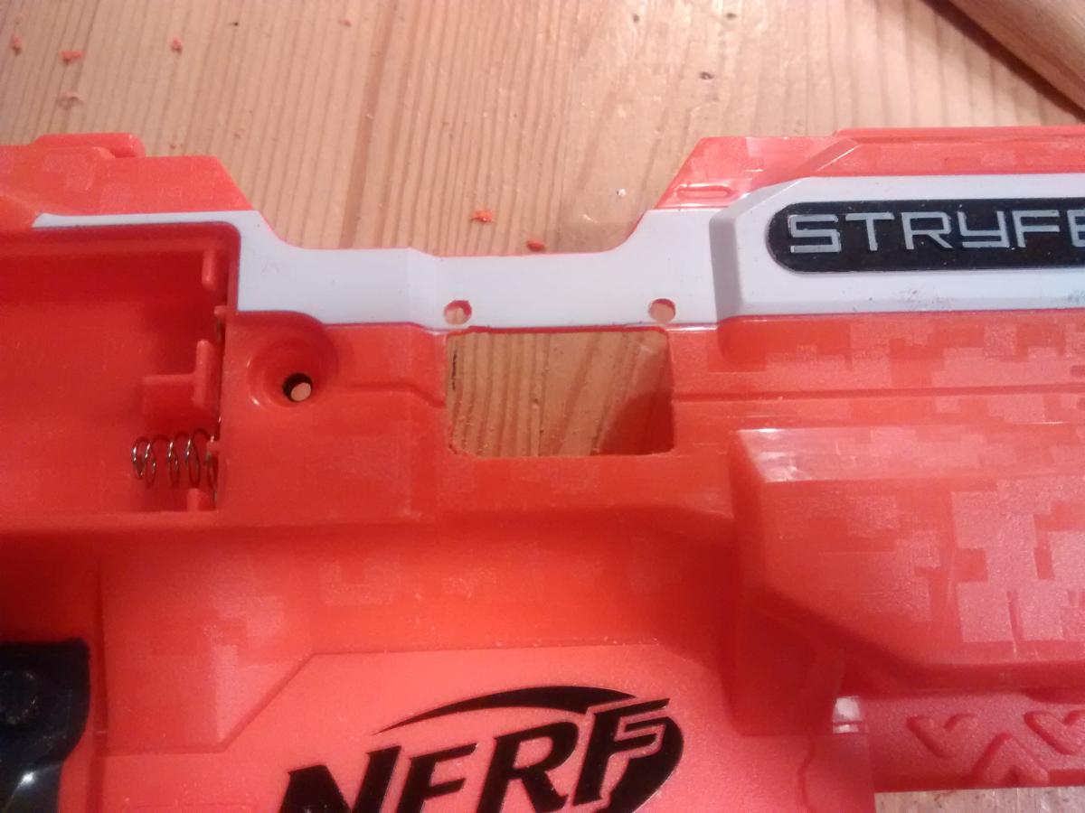
c. Cut a hole in the shell where you want your display to be located. Not that only a certain part of the display is actually used to for displaying content, and that’s the part with the screen protector over it. Once the hole is cut, file it down for smoothness. It doesn't need to be that clean; just look at mine.
Here’s how I placed my display:

d. Line up the display to the slot you just cut, and drill some holes where the top screw holes of the display are. I recommend using only two, both at the top, because the vexing angle of the magwell may get in the way of using the bottom securing holes.
Here’s what mine looks like, from the outside. The cut itself isn’t too smooth and it may not be too aligned, but it does the job.
e. Drill some holes for the two switches required: magazine size selector and power switches. I attach the switches just yet, as it will be much easier to solder them first and then adhere them into the holes.
I put mine like this

The BLACK is where I put the magazine size selector switch, and the BLUE is where the power switch is, with the little nub of the rocker protruding from the hole. Keep in mind, if you place the power switch where I put mine, you will have to shave off a little of this nub on the other side so the blaster can close:
The nub has already been removed here.

f. All the shellwork is now completed, and now the blaster must be rewired for recycling of the switches. Rewiring is not completely necessary, if you want to use different switches for the magazine insertion detection and trigger pull detection. Make sure to keep the magazine release switch and the jam door lock switch, as they will be repurposed.
The jam door lock switch has three pins, while the rev switch and the magazine lock switch should have two.
g. Reassemble the blaster, make sure it all works, but don’t close it up.
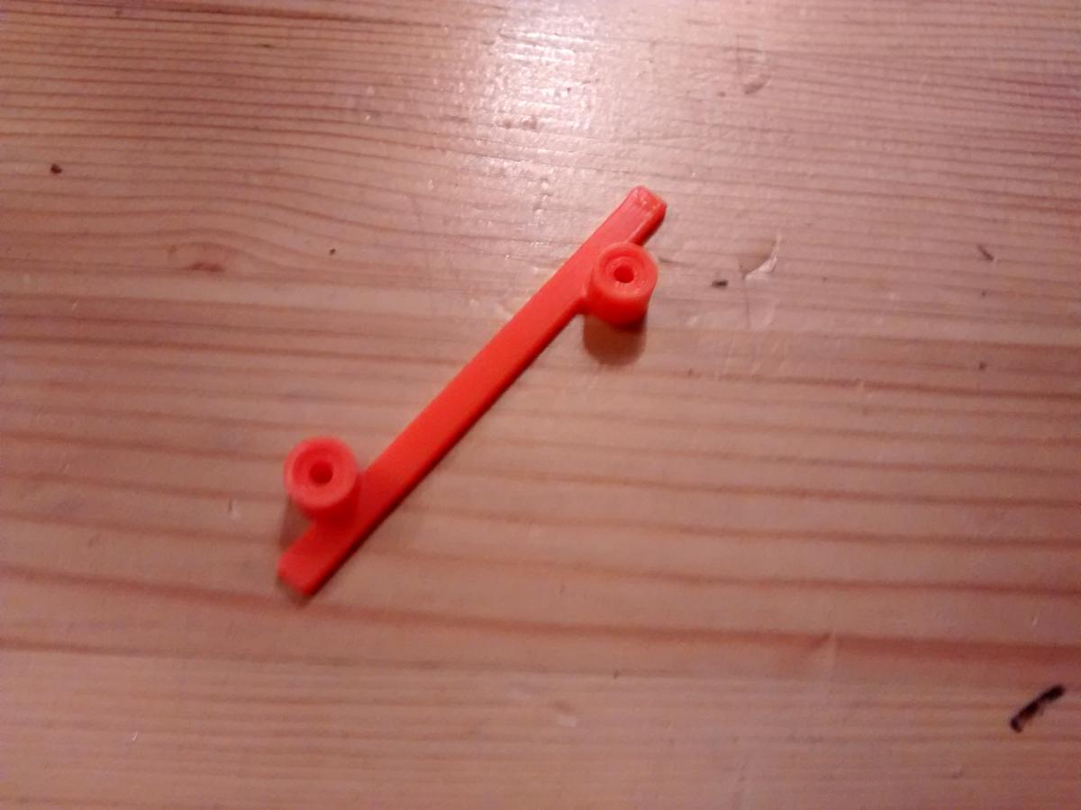
When reassembling, this part does not need to be reinserted, the covering of internal wires in the magwell, as it will get in the way of the display:
3) Electronics
Now that the blaster is complete, the electronics portion of it has to be done. This is the last step(s).
a. Make sure to desolder the headers pins, the little pokey legs sticking out of the board, of the display and the Pro Trinket, if they came with it. They will get in the way of soldering the wires, and trust me, it’s a lot easier to solder them onto the tiny holes than onto the header pins.
I desoldered the headers by first, pulling off the black spacers from the pins, and then desoldering each and every pin off. Don’t worry about getting all the solder out, It won’t be an issue.
Headers pins are often used while testing, so the entire board itself can just slide right into the breadboard.
b. Let’s solder all the switches individually before soldering them onto the Pro Trinket. Make sure all the wires are long enough, 4” - 5” should be plenty and keep track of which switch is which.
Here’s how I soldered them:

c. With the switches all soldered, let’s hit the display now. Make sure all the wires are long enough, 5” - 6” should be plenty. It should be something like this, with the wires long enough to be able to be soldered onto the Pro Trinket:
d. Now that the soldering is done on all of the components, solder them onto the Pro Trinket, with the wires of each going into the board as specified by the images.
As a reminder:

I solder them by first stripping and tinning a tiny piece of the wire, a little less than ⅛ an inch. Then, I slide it through the hole of the pin I want to solder it to, and warm up the upper part of the wire. Once the wire is hot enough, I melt some solder onto the base, where the hole of the board meets the wire.
If there is already solder in the holes, possibly from the removing of the header pins, that blocks the insertion of a wire from the first method, simply warm up the solder, which can be done by either touching the solder itself or touching the gold color surrounding of the hole, until the solder liquifies. Then, while the solder is still in liquid form, push a tiny piece of the wire through it. Once the solder cools, it should be strong, but if it’s not, simply repeat the second part of the first method to get more solder onto the connection for extra strength.
e. The soldering is almost all complete! Now we just have to install the components as a whole. Let’s put the display in first. Feel free to remove the screen protector now. Insert the nuts and bolts into the holes you drilled and the screw ports of the display. I actually placed a dab of hot glue on the nuts to prevent them from loosening under the vibration of the motors.
Mine look like this:

Apologies for worse image quality, but I zoomed in from another image.
f. The power switch can simply be placed where the jam door lock used to be, but a bit of dremeling may be necessary. Solder it to the correct leads of the NERF battery leads. If placed in this spot make sure to shave down some of a protruding nub from the jam door, like so:

g. Next is the magazine size toggle switch. Simply place it in the hole, and make sure it’s still pressable. Use epoxy putty, or any adhesive or your choice, to attach it, but don’t use hot glue as it is extremely weak and will fall apart fast. It’s fine if the epoxy putty spews out. That’s what mine is like.
Here’s what my magazine size toggle and power switches look like:


h. Make sure the ground of the NERF battery lead is connected to the power switch, and the other connection from the power switch is connected to the ground pin of the Pro Trinket. Also, the + pin on the Pro Trinket should be connected to the + lead of the NERF battery tray. Soldering is now complete! Insert some batteries, flick the power switch, and a green LED from the Pro Trinket, indicating power, should light up, with the display powering up shortly! If not, make sure the circuit is correct and the program is uploaded.
i. Place your Pro Trinket next behind where the trigger mechanism goes, underneath the roof of the shell. There is a ton of extra space here where nothing will get in its way, like so:

j. Place the magazine insertion detection switch where the magazine lock switch used to be, underneath the panel near the magwell in front of the main trigger, and make sure it is pressed by the little angled piece that sticks out. This will make sure that all magazine insertions and removals are registered by the Pro Trinket. This switch is secured with the panel, previously keeping in the locks, so epoxy putty or any type of adhesive is not necessary here.
k. Next is the switch to count the trigger pulls. Place it wherever you want, but make sure that when the trigger is pressed, so is the switch.
Epoxy putty it into place. Here’s where I placed mine, where it won't get in the way of any moving parts:

l. Your blaster should already be reassembled, just place the other half of the shell and it’s ready to go!
m. This step exists because the first letter of my name starts with ‘m’.
But here's a final internal picture for reference:

Using Different I/O Pins: (Requires “coding”)
At line currently 79, there should be a line like this:

Simply change the values of the numbers. The first value, corresponding to the trigger counter switch, should correspond to the pin you are to solder the trigger counter switch input wire to. The second value corresponds to the magazine detection switch; the third magazine size toggle.
There are comments in the code to help you with this.
Changing the Various Magazine Sizes: (Requires “coding”)
Underneath the code storing the values of the pins is the code to store the values of various magazine sizes, currently line 96:
Edit the values to whatever you want. You can even remove some of them or add your own. But remember, when the magazine toggle switch is pressed, it selects from left to right, and then starting back at the first(zeroth) value when it reaches the end. Also, the first value will be the default value, this is what the current ammo will be when the microcontroller turns on.

There will be comments in the code to help you with this.
Notes:
- The resistors for the buttons may not be completely necessary, as in my testing, I saw their absence didn’t change much.
- Both the Pro Trinket and Trinket can be directly powered by the same battery as your NERF blaster, unless it exceeds 16v. If it does, consider a way to drop the voltage or power it from another battery source.
- With the use of other mircocontrollers, many other components may be needed, including a linear voltage regulator and its other corresponding resistors, capacitors, etc. That’s why I chose the Pro Trinket, as it doesn’t require these.
- The current draw of this entire ammo counter is low, so you don’t have to worry about that
- I am aware that the code isn't that good. It's not my best, not my neatest, unconventional, and it's not too efficient for working with microcontrollers, but it should be fine for this application.
- There are comments in the code, so the inexperienced can read it and see what's happening
- No special magnetic magazine size detectors. I just think they're too much work and not worth it. But don't worry, a new and better method is coming soon.
- This will not work on some blasters. I am developing a method for those, too.
- When a magazine is not inserted, the display will always show 0.
- A magazine has to be inserted before toggling the magazine sizes and having their values show up on the display.
- Clearly visible display outdoors, due to the decently high brightness of the display as well as the high contrast between the black background and white text, as well as nicely lit up indoors, without being too bright.
- Be sure to keep the magazine lock switch as the magazine insertion detection switch, as the pins are connected when the switch is not pressed and disconnected when the switch is pressed, so I anticipated that in the code.
- When using the Adafruit Pro Trinket, once the power is turned on, it will enter bootloader before turning completely on, so the display will not power on until a few seconds.
Links:
Website: In Development
Video Tutorial - Shell Modifications (Part 1)
Video Tutorial - Electronics & Software (Part 2): In Development
Uploading the Code: In Development
Closing Remarks:
Purchase:
MANY more features soon to come, with complete tutorials for all of them, stay tuned!
Any questions, comments, problems with this, please PM me or comment below.
Thank you so much for reading!
Edited by Ming Batt, 01 January 2017 - 08:44 PM.