So, since it's time for post #500 and I've been talking it up for awhile, I'm posting my Ergonomic Retailiator mods. Basically, a pump-action setup and a collapsible stock. Both of my builds use 3d printed parts, neigher require 3d printed parts when used on a Retaliator or other springer. I fully admit stealing the base 3d models I used to make this from Thingiverse and the Rainbow Clan, links to their parts are at the bottom of the page. I extensively modified all the parts, though the ESLT plate is the only one that didn't really require it.
Final product:

The whole project took an hour or so once I started working in earnest. Knowing how it's supposed to go now, it'd probably take less.
FYI: Priming is a tad rough. This is because there is a bump in the body of the blaster. I think doubling up on the priming bar might help, or putting it outside the stock slide but drilling through the slide to engage the bolt directly, or adding a piece of something to ramp it more gradually, or grinding down the blaster body. I'm not sure I care enough to take the time to do those things right now.
Tools used:
- Drill
- Drillpress w/ 3/8" router bit (slot cutting; if you do it differently you might not need to cut slots. You can obviously cut slots however you please also - hand saw, dremel, piece of mason's line threaded through 1/16" holes drilled at the corners of the slot and used as a saw, whatever)
- Screwdriver (#1 phillips for the shell work, whatever you need for the screws/bolts you picked for the new stuff)
- Saw (I used Japanese-style pull saw. You can use basically any saw, or a PVC cutter, or a pipe cutter, or mason's line again, or whatever else you cut PVC with. No shell cutting req'd)
- 1/8", 3/16", and 1/4" drill bits.
Materials used:
Stock:
- (CTF) 1-1/4" Sch. 40 PVC Pipe (+/- 6", cut-to-fit)
- (CTF) 1" 200 PSI PVC Pipe (Thinwall - it's used for yard drains while Sch. 40 is used for household plumbing drains, so look/ask in the yard drainage department of your large home improvement store. I got mine at Lowes). Thinwall is important for fitting over the plunger tube buffer that sticks out of the back of the blaster. (Again, Cut-to-fit).
- (1) If you're using the stock for any blaster, use thinwall and this 3d printed adapter:
 Stock_Combined.stl 169.42KB
423 downloads. If you're just using it for the retaliator (and other blasters with the buffer tube) you can probably just attach the thinwall direct to that, maybe with some e- or packing-tape to stabilize it. The way it's built won't allow it to be readily removed on any blaster.
 - (1) If you want it, the 3d printed butt-plate from the above link. Otherwise, a 1-1/4" T works in a pinch, or whatever you want to hobb to gether (1-1/4" PVC endcap or plug secured to a plate)
- (1) I haven't done this yet, but a plate to make the buttplate stronger. I'm planning to use plywood or a chunk of 2x4.
- (5) #8 x 1/2" screws. I use hex-head, you can use whatever drive style you want.
- (1) And lastly, and most importantly: A 1/4" X 1-3/4" Long cotterless hitch pin (Lowes H#881123).
Pump-Grip:
- (CTF) 1-1/4" Sch. 40 PVC (+/- 12", Cut-to-fit)
- (CTF) 1-1/2" 200 PSI PVC (Thinwall, see note above)(+/- 4", Cut-to-fit)
- (2-3) #8 x 1/2-3/4" bolts & appropriate nuts (depends on your priming bar, mine is pretty thick. If nessecary, go long and cut to length later)
- (1) M5x16 bolt, washer, and nut. (Again, my priming bar is thicker so you may need to cut the bolt or use another nut or two to get the spacing right.)
2017 UPDATE: User Rook1872 on Reddit was asking for ideas while doing this project himself and discovered that a socket-head #6 can sort-of press fit into the sled as well. Here are his pictures. He said keeping the blaster's slide helps structurally to prevent rocking and with the look; I agree and might have done it at some point with my solution here.
- (CTF) Something to use as a priming bar. I'm using scrap aluminum from a screen door that approximates a U-chanel. I suspect a wooden yard stick or several paint stirrers glued (With wood glue! Nothing else!) together would work as a minimum, but I haven't tried it. They're usually free or nearly so, so I won't feel bad if you do and it doesn't work.
- Optionally, some kind of glue to stiffen it up.
- Optionally, This part for the grip:
 Grip.stl 294.42KB
432 downloads. Or just use grip tape. Or nothing.
Pretty sure that was it. It's an easy mod.
DISCLAIMER: I accept no responsibility for you being bad at building. Use caution with power tools, don't get hurt. I am not implying any kind of guarantee about the correctness of this information. Read all instructions prior to building. Build at your own risk.
Stock Instructions:
This is a model showing what you're building:
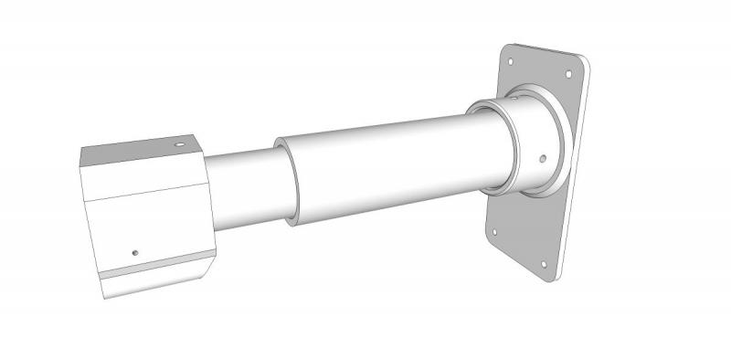
Steps:
If you're printing parts, get those together.
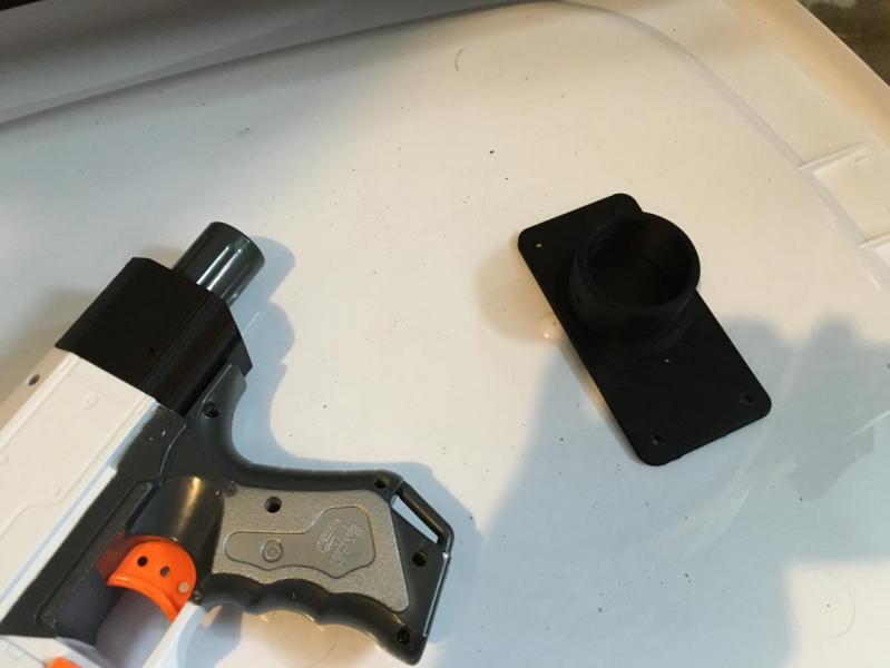
Once that's done, cut your 1" PVC and 1-1/4" PVC to length. You want about 2" of overlap between them. I did this by holding the pipes in their places while holding the blaster in the firing position and just guessing at what length would be good for me. I suspect 6-8" is a good starting place. Cut the 1" first, then the 1-1/4" as you can slide it on the 1" and see what length will work best on the blaster. If you've got the material, cut long (12"+) and then shorten it later.
Secure the 1" PVC to the blaster with a #8x 1/2" screw. Drill a pilot hole through the PVC and into the shell. You don't need to drive it all the way in if you're not using the printed part, just enough to keep it in place. You don't want it to mess with the plunger rod. If you're using the adapter, sink it but not too tightly as you don't want to split the printed part.
Secure the 1-1/4" to the butt-plate or T or whatever you're using.
Put them together and check the fit on your body in the positions you want (I just did 2 - open and closed).
Using a 1/4" bit, drill all the way through the assembled collapsed pipe stock. You want to only drill one hole in the 1" pipe, about 1" from the open end of the pipe - with it apart mark where that is on the 1-1/4" by holding it next to the 1". Do it in one push all the way through - this is how the hitch pin will travel. This is easier with a press, center punched holes, a V-block, and predrilling. I did it by hand. Check that your hitch pin fits all the way through and locks in. See picture
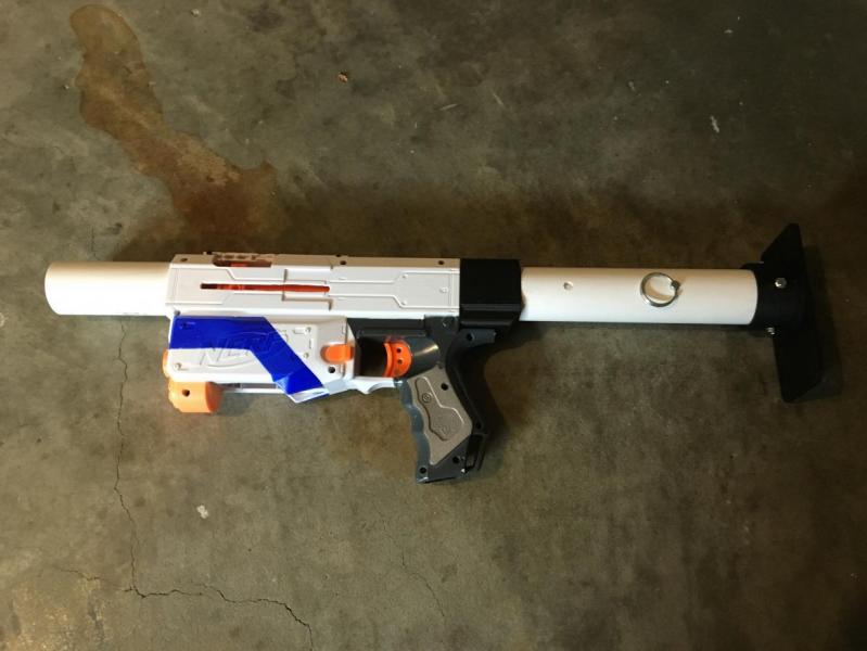
Remove the 1-1/4" rear stock piece and drill a second hole at your extended point all the way through again. This needs to be 1-2" inside the open end of this pipe. The tricky part here is that it needs to line up exactly with the other holes. It's not pictured, but I missed and had to widen the hole on the back of the pipe when I did mine. I did it entirely with a hand drill, so you should be able to as well, but a press set up with a proper jig would make this more reliable.
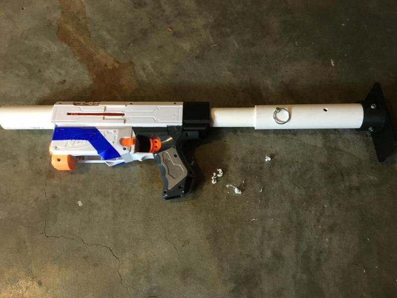
Put the 1-1/4" back on, slap the pin in, and you're done. It's not super quick to change, but you could easily do it in the field while in cover.
Pump Instructions:
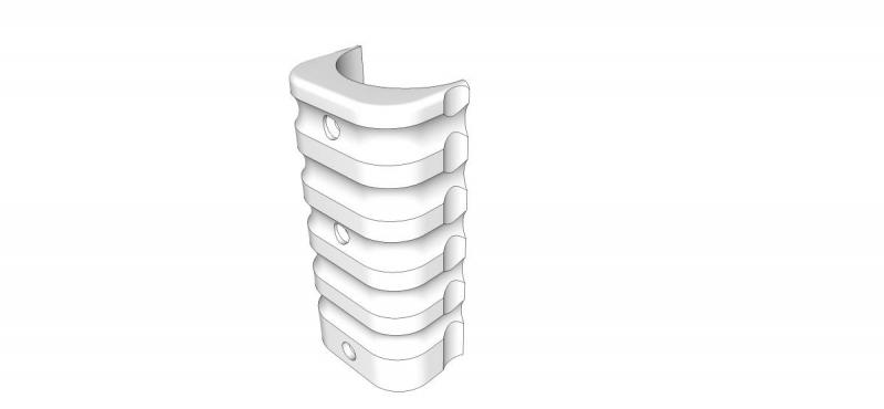
Here's a model of the grip I used:
Steps:
Pop the blaster open, then remove one (or both) of the screws holding the slide action and remove it. You don't need it except cosmetically. I kept half on and will probably cut it short and put it back.
Cut your 1-1/2" PVC to length to use as your pump-grip. This should be +/-4", or the width of your hand, or the length of your printed grip.
Cut your 1-1/4" PVC to length. This is done by A) sliding it over the barrel stub, which the PVC conveniently fits right on (Mine might be magic, so you may need to ream it a bit or make a relief cut in the PVC so it can flex wider) and B ) Marking a point an arbitrary distance forward of the face of the blaster that lines up with the blaster in the primed position - check it with your grip in the primed and unprimed positions before cutting.
Get your priming bar and check that it's long enough to go from the bolt to the pump grip in both open and closed positions. Then drill a 3/16" hole in one end for your M5 bolt. Drive the bolt in and put the washer and nut on the oppisite site as shown.
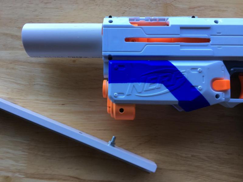
This bolt (and only this!) fits into the slide:
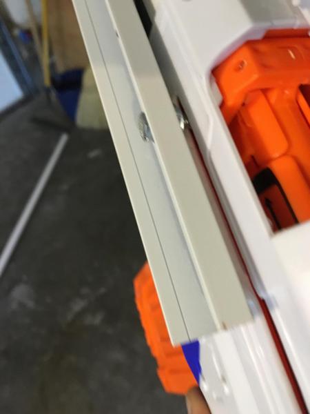
I suspect that others would work, but this was the first I found that fit so I'm sticking with it. Any good hardware store should have them, so it shouldn't be that hard to find.
Drill out your holes for the rest of the bolts in the pump-grip and line them up with the 1-1/4" PVC and the priming bar. I had, again, done it by hand and poorly, so mine is all askew. Next time I'll try to be better, I promise. Drill the further hole at the end of the slide action through the 1-1/4" too so you know how long to make the slot.
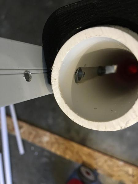
Make the slot between those holes. I needed it to be 3/8" to fit both my router bit and, as a happy coincidence, my bolt size.
Get those bolts through the assembly and tighten as much as you can.
On the 3d printed part - It isn't optimally designed for the position of the priming bar, so I drilled through it in addition to the grip. If you want to modify the print, stretch it so the grip part is further from the pipe.
Once it's assembled, you're all done!
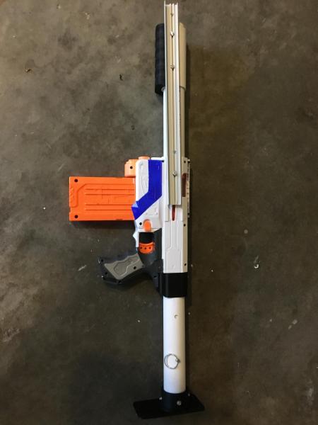
You also might note that I didn't ever actually attach the 1-1/4" to the barrel stub. You probably should do that, but I didn't because the bolt sled should stop the pump grip from hitting the 1-1/4", and I can't see how else it'd come off normally. If you had to modify the 1-1/4" to get it to fit or if your fit is looser than mine, you should attach it somehow. As long as you use screws or only glue to the barrel stub, it should still be possible to disassemble the blaster.
Links to original parts I used to design the parts included here:
Grip I hijacked
Stock adapter I hijacked
ESLT; I just hijacked the Butt-plate
Edited by Meaker VI, 18 January 2017 - 03:19 PM.


