Zombona, perhaps the NIC's biggest Boomco fan, developed a method to seal the air release holes in Boomco clips (see here) in order to utilize blasters' air output more efficiently. This has been shown to substantially increase muzzle velocity/range out of the various spring-powered Boomco blasters like the Dynamag.
Unfortunately, the Rapid Madness (RM) has "dart sensors" that ride in these air release holes and thus prevent the use of sealed clips. Here's how to remove the dart sensors while keeping your RM functional:
First, you'll have to remove the ring that is glued around the RM's pump. It was quite a bit of work to pry mine off.
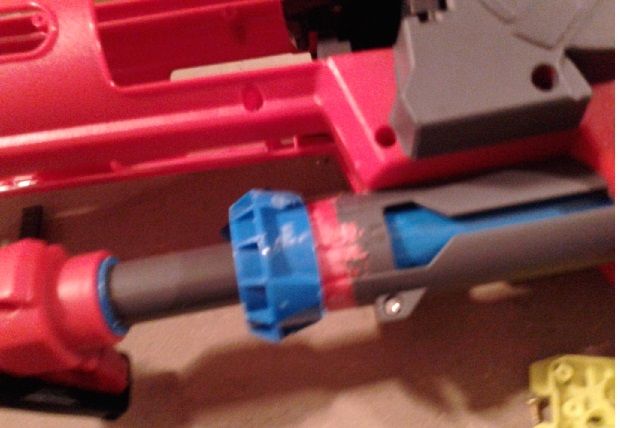
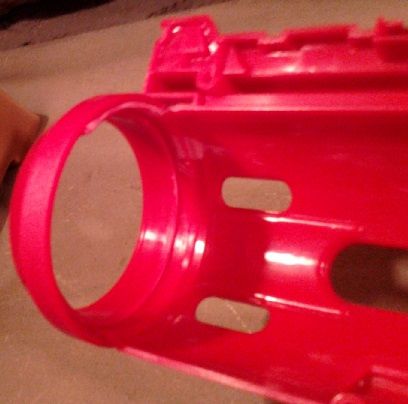
There is a second glued ring at the muzzle. I was able to just pry the blaster apart after removing the screws to break the glue at the muzzle, but you may choose to simply cut off the end of the barrel.
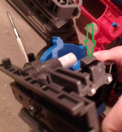
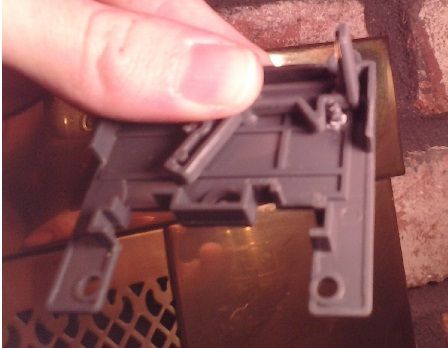
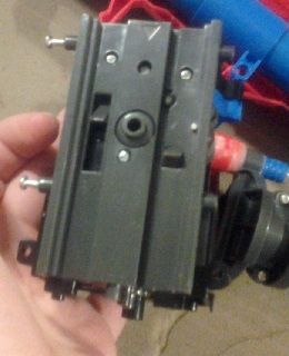
Once you've gotten the blaster apart, pull the firing valve assembly (infamously called the "black box") out of the shell.
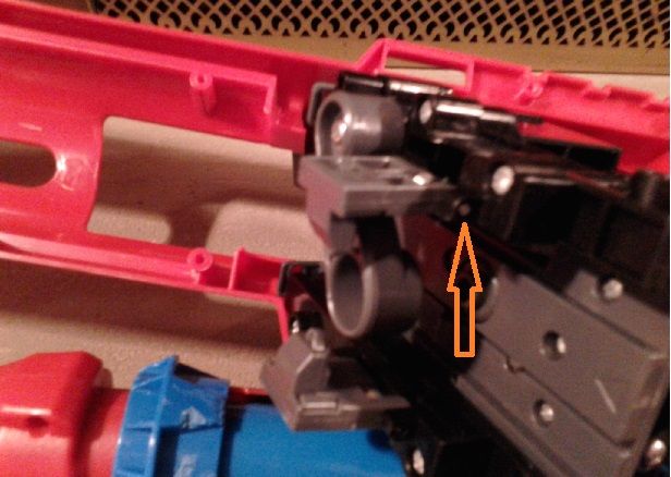
The side of the black box that rested against the right side of the shell is the side of interest for this modification. It's this side:
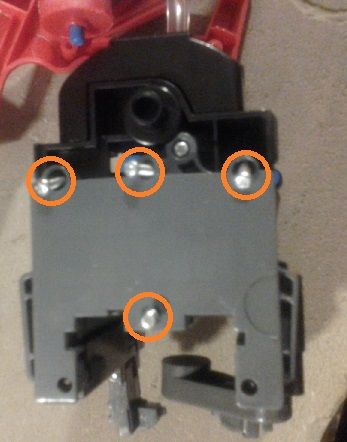
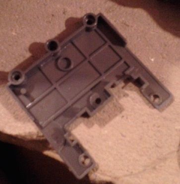
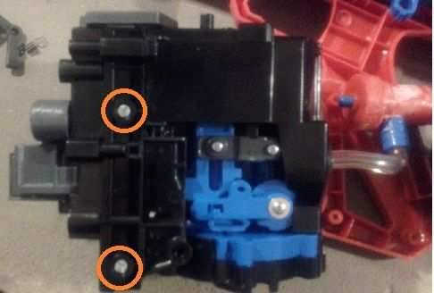
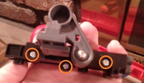
Remove the circled screws to access the dart sensing mechanism, and you'll see this:
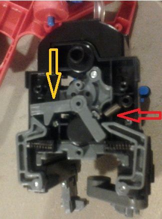
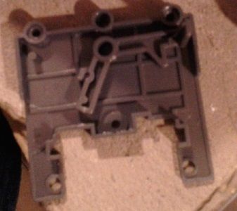
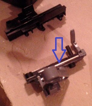
Remove the extension spring indicated by the red arrow. The piece indicated by the yellow arrow is what I'm going to call the bump trigger. It's essential in order to make the RM fire in full auto because when it's pushed by the dart sensing arms it lines up with this catch:
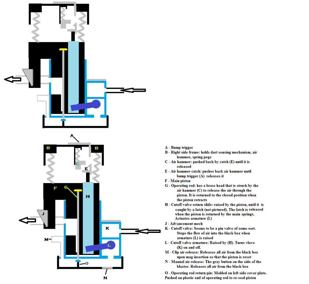
You won't be able to see this catch unless you disassemble the black box a lot further than this guide requires. It gets moved back and forth, and (if the bump trigger is pushed into place by a dart) gets rammed into the bump trigger, completing the cycle and releasing air down the barrel. We are going to make the bump trigger stay pivoted towards the back of the blaster (where the tubing connects to the black box), so that it will be lined up with this catch all the time.
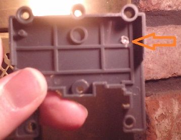
Anyway, moving on with this modification, flip over the grey plate that you removed earlier. The circle molded into it matches up with the circle on the bump trigger:
You need to use something to keep the bump trigger in this position. I chose to simply place a screw to hold it in place. You could use a short 4-40 screw, countersink , tap it, etc etc. I didn't even have a small enough drill bit, though, so I used a #6 wood screw to drill a hole here:
And then put in a spare nerf screw:
You'll reassemble by placing the bump trigger back on its pivot point without the extension spring, and then turning it clockwise until it stops (aka moving it towards the back until it stops). I suggest putting it together and test-firing it at this point to make sure it works. You should be able to fire it with or without a clip inserted.
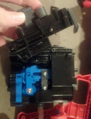
Now we need to remove the dart sensing armatures. Remove the right side cover plate again then remove these circled screws from the top of the black box:
Take off the top clip guide rail, which has that extra spring-loaded armature on it:
Do the same with the bottom guide rail.
At this point the front will look like so:
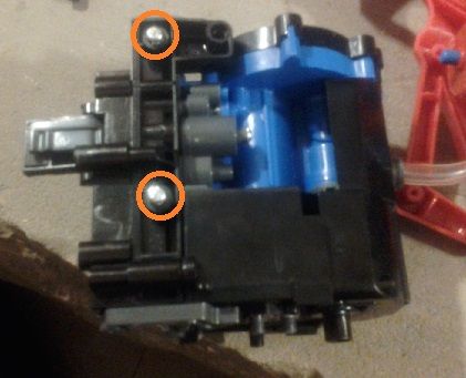
Take these three scews out of both guide rails.
Now you can take out the metal rod from each guide rail, which has the dart sensing armatures attached
Reassemble the guide rails. There is one more, torsion spring-loaded dart sensing part that needs removed from both the top and bottom guide rails. You could try punching out the pins, but I couldn't get them out. I suggest leaving the part of the hinge molded onto the black box, but you could cut the end off the spring-loaded armatures.
After this, reassemble everything and you'll be able to use sealed boomco clips.
Special thanks to Buffdaddy and Zombona for previously detailing how to disassemble the black box.
Edited by jwasko, 02 March 2016 - 03:19 PM.