So for the later part of the past few months I have been working on a Stryfe Falcon 130 build. I want to add some sort of braking to the motors so when I let go of the rev trigger the motors stop almost immediately. I have seen videos of finished projects of this type but no diagrams on how the circuit is set up. I know I need to run a wire from the motors to the switch but am un sure if it's off of the positive or negative wire and to what terminal on the switch (I think it's to the Normally closed terminal (also what terminal is that, my wiring loom is coming to me prebuilt from http://www.blasterte...3_13607495.aspx)). If someone could help me out in pointing me in a direction as to a diagram or better yet pictures, I'd be more than appreciated. If it helps any I plan on running this blaster off of a 3S Lipo (not sure if it makes any difference)

2 replies to this topic


#2

Lunas
-

- Members
- 142 posts
Member
Posted 17 July 2015 - 09:07 PM
not really for motor braking it is connecting the positive and negative side of the motors the diode is the actual thing you want though as it serves the same purpose and is actually something your supposed to do with dc motors or inductors...So for the later part of the past few months I have been working on a Stryfe Falcon 130 build. I want to add some sort of braking to the motors so when I let go of the rev trigger the motors stop almost immediately. I have seen videos of finished projects of this type but no diagrams on how the circuit is set up. I know I need to run a wire from the motors to the switch but am un sure if it's off of the positive or negative wire and to what terminal on the switch (I think it's to the Normally closed terminal (also what terminal is that, my wiring loom is coming to me prebuilt from http://www.blasterte...3_13607495.aspx)). If someone could help me out in pointing me in a direction as to a diagram or better yet pictures, I'd be more than appreciated. If it helps any I plan on running this blaster off of a 3S Lipo (not sure if it makes any difference)
You should put a diode across the terminals of the motor this will stop them from generating power and feeding it back into the circuit as they spin down. Add the diode pointing towards the positive on both motors this is the safest method and costs very little i think 2 diodes can be had for like 10 cents...
Or you can take the jam door switch and put it as the new rev switch the second and 3rd pin 2 pins will be the on off for the rev circuit and the 1st pin connected to the negative on the battery tray is the brake...
http://www.mouser.co...fX4nEEHllp3mZcc .18 cents each you need 2
Edited by Lunas, 17 July 2015 - 09:44 PM.
#3
jwasko
-

- Moderators
- 1,021 posts
PowerBeard
Posted 17 July 2015 - 10:06 PM
You have a better switch coming with the loom so don't switch back to the jam door switch.
In the picture on Blastertech, the switch has three poles. They don't have a closeup picture of the switch but they should be labeled "C" (common), "NO" (normally open...this circuit will be completed when you push the botton) and "NC" (this circuit will be completed when you are NOT pushing the button.
The pole that has no wire connected should be "NC." I don't know for sure if the red wire or the blue wire is connected to "C"
Basically, you need to make sure that the blue wire is on C/common and the red wire is on NO/normally open; if not, you'll need to switch them.
Then, splice a new wire into the black wire and connect that to the NC/normally cosed terminal.
Once you do this, and BEFORE YOU CONNECT ANY LITHIUM BATTERY:
Find a way to connect some regular AA batteries to test. If they get warm or something doesn't work, that means you have some sort of battery short. If you short a Lithium battery, it could/probably will start a fire.
I've modified the wiring diagram available on Blastertech. Assuming the blue and red wires are connected to the switch like this, you just need to add the green wire:
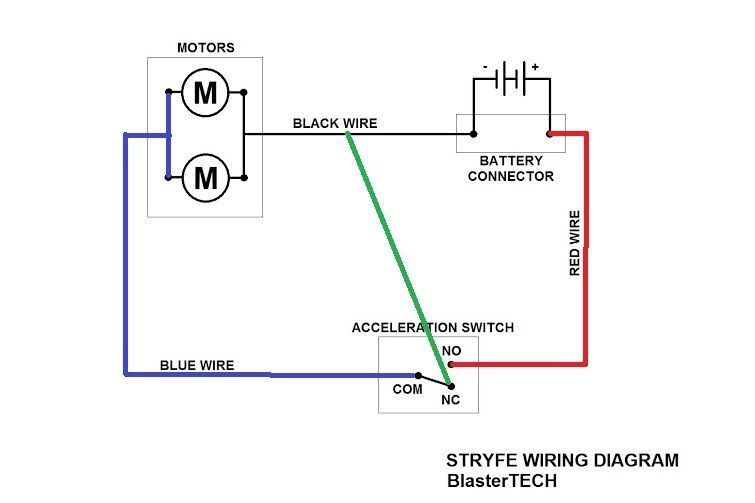
The green wire can connect anywhere along the black wire from the battery connector to the motors.
In the picture on Blastertech, the switch has three poles. They don't have a closeup picture of the switch but they should be labeled "C" (common), "NO" (normally open...this circuit will be completed when you push the botton) and "NC" (this circuit will be completed when you are NOT pushing the button.
The pole that has no wire connected should be "NC." I don't know for sure if the red wire or the blue wire is connected to "C"
Basically, you need to make sure that the blue wire is on C/common and the red wire is on NO/normally open; if not, you'll need to switch them.
Then, splice a new wire into the black wire and connect that to the NC/normally cosed terminal.
Once you do this, and BEFORE YOU CONNECT ANY LITHIUM BATTERY:
Find a way to connect some regular AA batteries to test. If they get warm or something doesn't work, that means you have some sort of battery short. If you short a Lithium battery, it could/probably will start a fire.
I've modified the wiring diagram available on Blastertech. Assuming the blue and red wires are connected to the switch like this, you just need to add the green wire:
The green wire can connect anywhere along the black wire from the battery connector to the motors.
Edited by jwasko, 17 July 2015 - 10:42 PM.
-Jwasko, STILL Sole Surviving member of Steel City Nerf and Sober Sister of the Sex Dwarves
We NERF ON all day, and FUCK OFF all night
0 user(s) are reading this topic
0 members, 0 guests, 0 anonymous users

