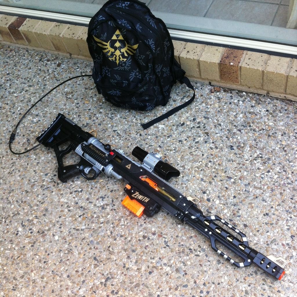
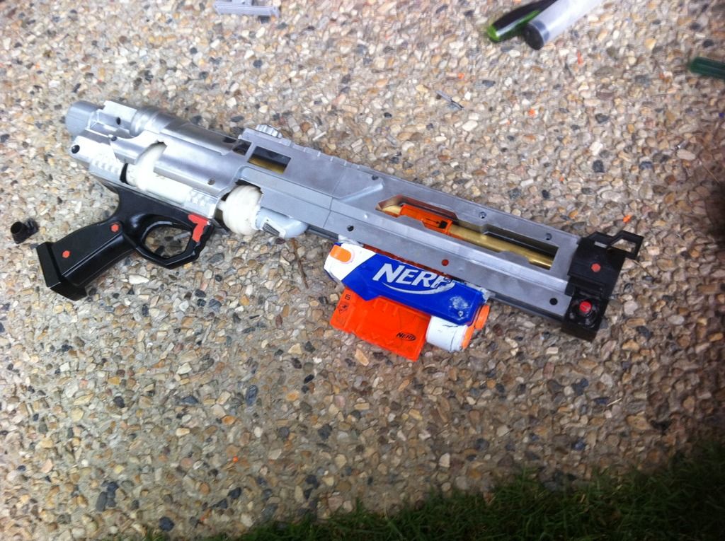
First, the money shot:
Now, what I required for the blaster itself:
-Max Force Shadowhawk (the blaster shell)
-4B tank, with or without a lever trigger (I'll go through optimizing it in the build, how I have done it is due to how I received the tank second hand, if you choose to replicate this, I will show where to put the hole for the air line.)
-Multiple lengths of 17/32" brass, 9/16" brass and 19/32" brass
-Epoxy putty, super glue and epoxy glue
-Any Nerf magwell of your choice (I used a Retaliator magwell in the absence of a spare Stryfe magwell, which would've made it more streamline and less blocky)
-20mm conduit tee and 90° bend piece
-20mm conduit (1/2" PVC for 'Mericans), approximately 30cm so you have spare bits to use.
-Air line
-Check valve for air line
-connector for your air supply
-Your choice of trigger (I used the Ret trigger after sacrificing the Ret magwell)
-Really tough wire of any diameter
-Small metal bar of any length but particularly thin diameter (the pins from N-strike boltsleds are particularly useful)
Alllll right, I think that's everything.
Let's begin.
First, gut your MFSH shell. Keep your bolt piece, your pump handle (optional) and all shell parts, except the pump rail. That shit is useless, as are most of the other parts.
Now, begin grinding out the shell ribbing around your trigger grip area, especially just above it. I put my 4B tank in (after completely removing the pump end) and left a base for it to lie on, and just ground out all ribbing that impeded the shell closing over the tank.
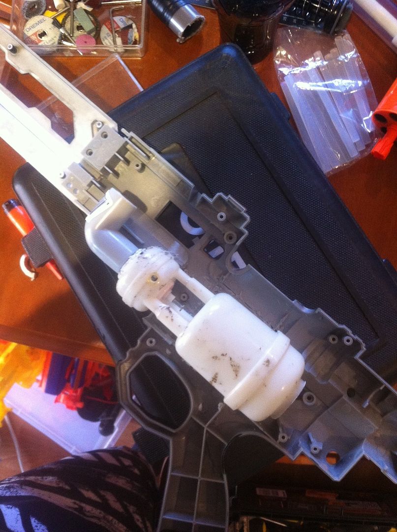
Once you have your shell able to close over your tank, you have multiple choices of what to do next. You can either do the air line to your choice of air supply (which for me is my "Zenith" backpack), followed by the lever trigger assembly, or you can do the breech and bolt action sections. I will go over the breech and bolt action sections first.
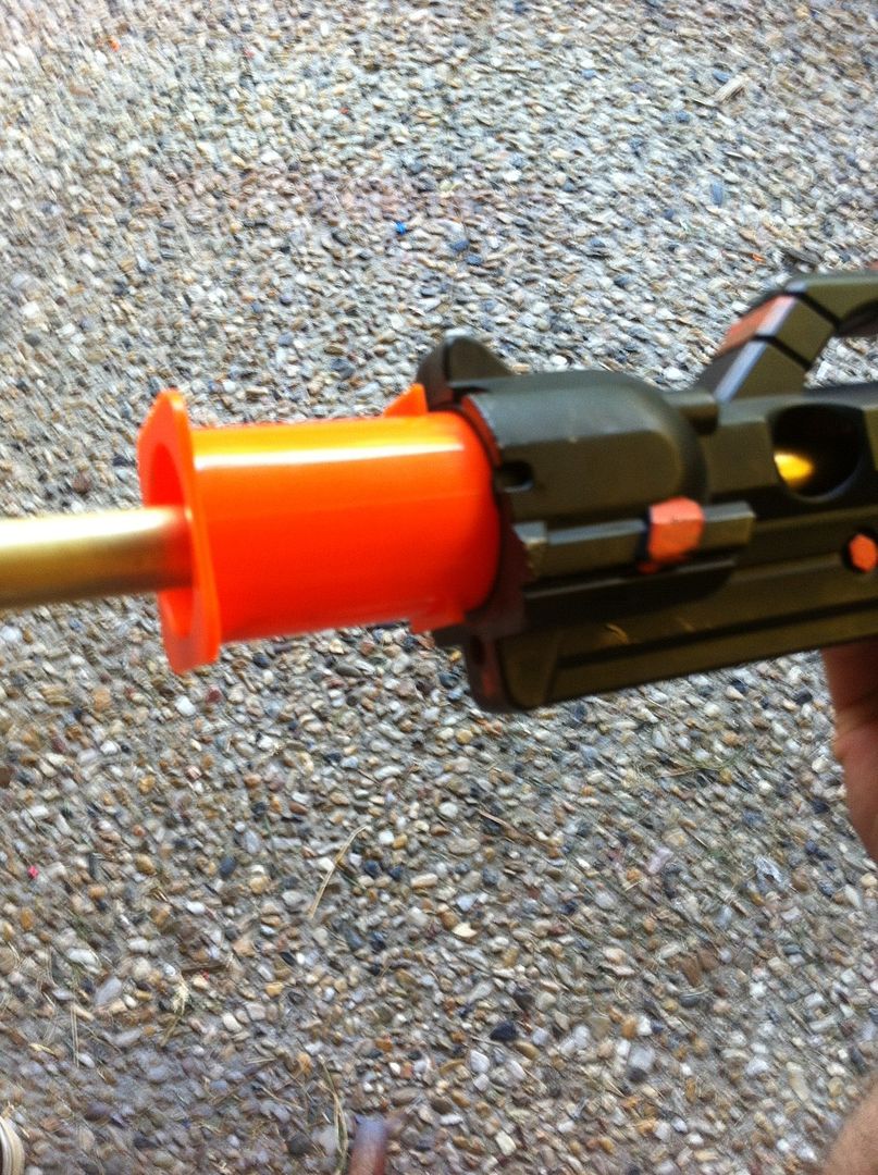
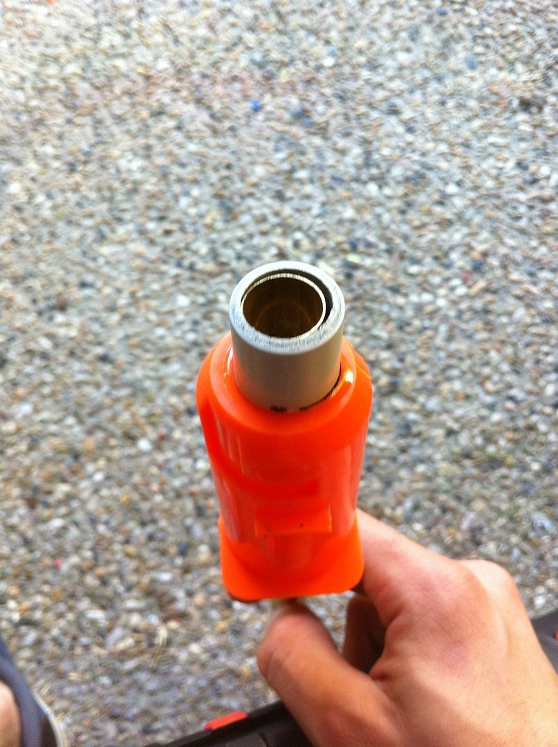
Okay, this section is a LOT of brass work and your tool of choice here will be a Dremel/rotary tool. Let's work on the brass muzzle first. This part I worked on to make detachable for transport purposes. It's wickedly simple to make.
First, take apart your barrel attachment, and take out the section of tubing that the blaster uses for its pitiful spitballs. Close the attachment again, and get either a 17/32" drill bit (not quite easy to find) or your rotary tool's grinding bit and widen the pipe guide's ribbing JUST enough to accommodate your first whole foot length of 17/32" brass. Insert, line up with the front of the muzzle so it is as flush as possible, and mark where the original pipe's "holding piece" sat, on your brass. Cut a length of 20mm conduit at that length, and fit it to your brass, epoxying it to the brass.
Do NOT allow it to become epoxied to the inside of the barrel just in case you feel like taking it apart later, which I haven't had to yet, but just in the instance that you actually do need to take it apart, better safe than sorry.
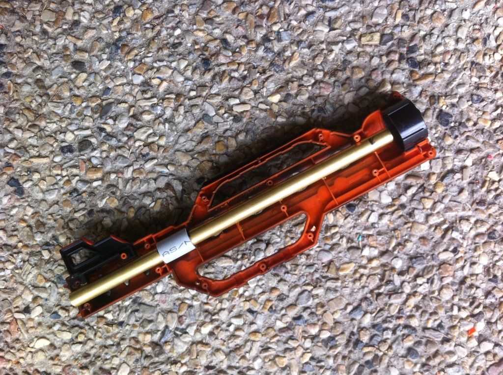
When it is finished curing, put the whole barrel extension back together. Do NOT fret about the back part protruding from the extension, that will come in handy soon.
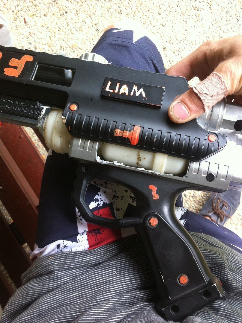
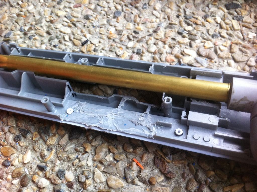
Let's start on the connection to that piece first. You will have to do the magwell section now too, so flex your shell integrating muscles and get to work. Here are some pics of my Ret magwell integrated from inside and outside. I do plan to go back and clean up the shell holes in front of and behind the magwell later on, but haven't got around to it at this stage.

In order to do this really effectively, you will have to first grind or drill out the pipe holes to accommodate your brass lengths up the top here. I lined the back of my clip up with the front of the opening on either side of the shell. The ribbing in the underside and inside WILL need to get ground out or cut off to accommodate a clip feeding from underneath. Start by grinding out the brass holes, sleeve some 9/16" and 17/32" to the muzzle brass, and run your brass right back to behind the clip.
After you have decided where to seat your clip, throw up your magwell section with clip inside and line it up with your shell as you see fit. If it doesn't fit, grind more shell ribbing until the clip can wrap around the brass.
Once it sits nicely with the brass between the clip lips, get to work making the magwell sit still. Putty is your friend, be liberal and grind/sand away at anything you don't like/want, after testing that your clip still feeds into the brass.
Now you have that section done, feel free to clean it up, however you see fit.
Here's a quick tip for ya: if you like a faster release magwell, use a Stryfe magwell. It's also more streamlined than the Ret magwell.
Time to go to work on the breech.
This is probably the hardest section of the overhaul, as the brass work is long, complicated, and took me a LOT of waiting, lubrication, and trial and error to get the breech and bolt action to function as smoothly as it does.
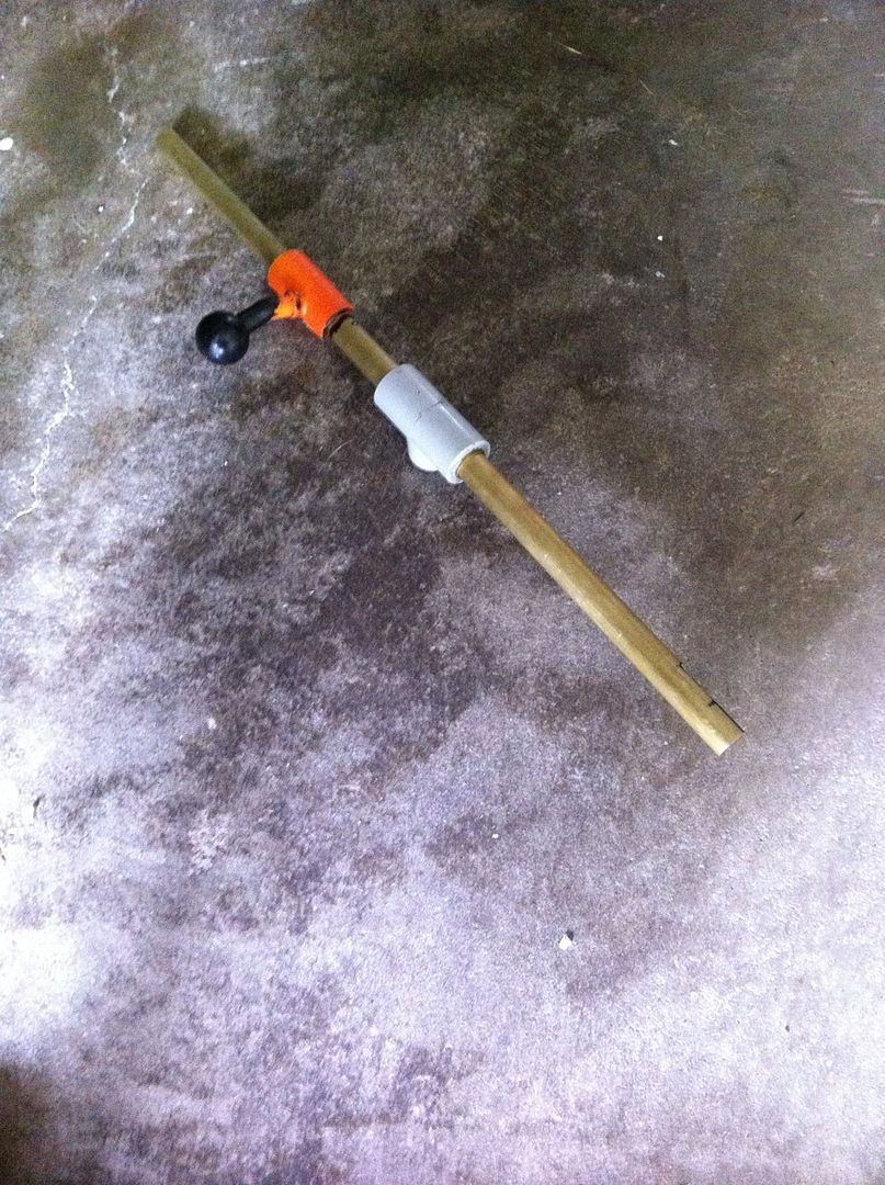
This part has a small section of preparatory work with the tank: prep some epoxy glue, and get your 90° bend connected one end to tank, one end to the bottom of the tee (You can leave the tee friction-fitted for now, epoxy it in later). Get your inline tee sections lined up with the brass you set up before. This may involve cutting your tee end and bend ends so that you can connect them as flush as possible.
Cut some 20mm conduit to join them properly. Next, cut 2 lengths of 2cm from your conduit and fit them into the inline section of your tee. You will now need to cut matching lengths of 19/32" brass and epoxy them into place in the 20mm conduit. I'll explain their function when we get working on the bolt action. You may want to have a "sacrificial" piece of 9/16" brass, VERY well lubricated, to sit between these two lengths of 19/32" to make sure they're perfectly aligned. This part was one of the most frustrating for me, and please don't hate me if it doesn't work first time. It didn't for me either.
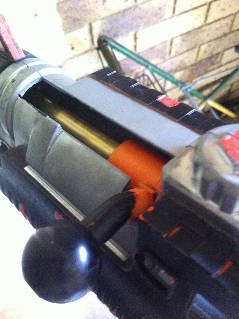
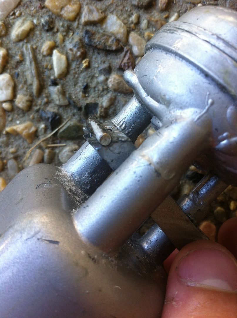
Once you have that working, your tee will look like this:
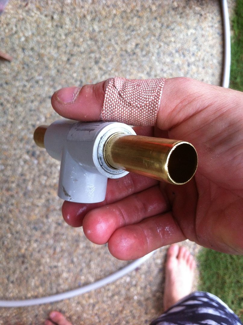
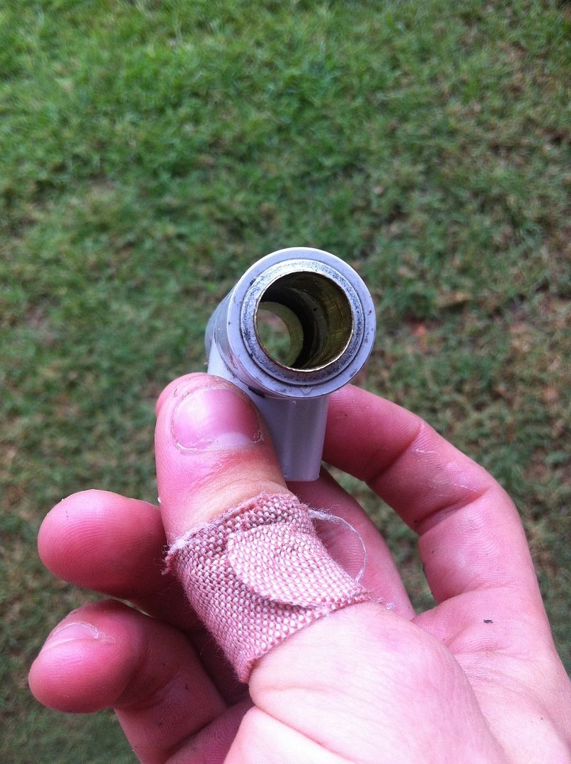
Alright, NOW we can get to work on the breech. Let's start by connecting the barrel extension to the breech portion of brass. Cut a 2cm length of 20mm conduit and grind out your barrel extension connector piece to accommodate 9/16" brass. Now cut about 5cm of 9/16" brass. Sleeve it over the back end of the barrel extension (which should've been 17/32" brass if you were listening) and sleeve the conduit over that. Do NOT glue anything yet. Now, connect your barrel extension connector to the barrel extension, while still separate to the blaster shell itself.
Feel free to NOW throw some superglue down inside the connector, to hold the 9/16" piece tight to the extension connector. We will make this more solid a little later. Sleeve some more 17/32" brass into the inside of the 9/16" in the back of the connector. Push it through until it contacts the extension's brass. Superglue the seam that the 9/16" makes with the 17/32". Now disconnect the barrel extension from the connector, and insert the connector gently into the blaster. If you've done it right, at this point your 17/32" brass will just sleeve beautifully through your clip lips. Close the shell. Grab that conduit section you cut for the extension before, and epoxy it to the front of your blaster over the top of your 9/16" brass connector piece. It will look like so:
If you want to make this connector piece even more solid, put some 20mm conduit on the inside of the connector and epoxy it to the brass as well.
Use needle nose pliers to widen the lip of the 9/16" brass a little, to make connecting to the extension a little more fluent and painless.
Now, if you've worked with Longshot brass breeches before, you will know what to do next.
CLIP HALFPIPE!
Or quarterpipe. Either will work, as neither of the two pieces comprising the brass breech are actually load-bearing at all on the breech end, and will not bend if you treat your brass and your blaster properly.
So get to work on your 17/32" piece. There are some really intricate brass parts coming up, so consider this your warmup.
Now this part is important to note: the brass piece you are using for the half pipe MUST end where the back of the clip is. Well, sorta. For my design, certainly helps for minimal brass cutting and for optimal breech seal.
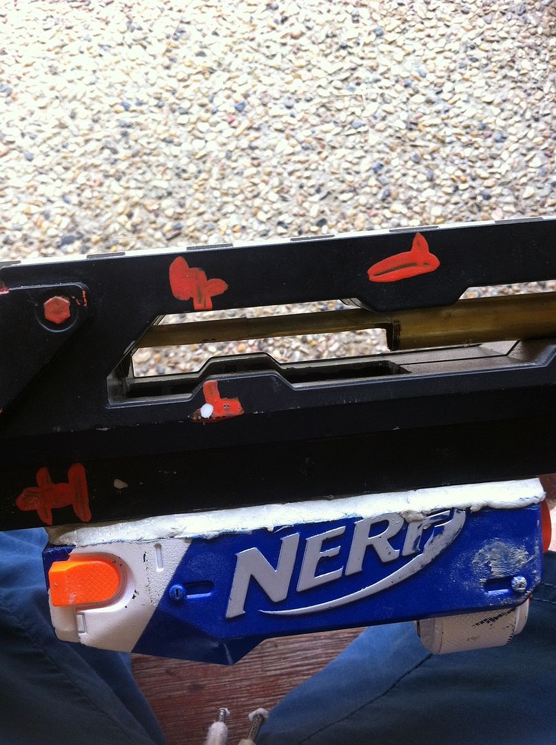
Next, we will prep the shell for accommodating a full-draw breech, because in its stock form, the bolt action is too short to accommodate full length darts. If you want to make it Stefans-only, sure, don't cut the bolt guide, but otherwise, I find that cutting back to the next rise in the shell is the best way to accommodate full length darts in the breech draw.
Right, you are gonna need to take very careful notes on the bolt assembly here. My design uses the tee section as the air flow section (duh), with TWO sizes of brass inside it to make the breech loading super-smooth, as well as eliminating dead space behind the tee.
First, get a full foot length of 9/16" brass. Where the breech section is, close it over the 17/32" brass and make your halfpipe/quarterpipe to the length you deem fit. Seal the breech after cutting your half/quarter pipe. That will sit inside the tee, and protrude from the other end. This is good.
Mark on the pipe where the tee shrouds over it. This will come in handy soon. (I forgot to take a picture of this section, I apologise if it is unclear.)
Now, sleeve a full foot length of 17/32" brass inside that, and position it further back inside the shell so that the back ribbing behind the bolt section accommodates it. This piece of brass is our "bolt guide", which will sit perfectly stationary while the bolt slides back and forth, and will streamline your bolt travel to be perfectly linear. Make sure your 17/32" brass sits nicely within the ribbing, grinding it slightly wider if you need to, and apply a small amount of epoxy putty to the brass on either side of the ribbing. Close the shell to ensure that the putty will mould to accommodate the ribbing. Once the putty has cured, you will be almost finished with this piece. We will deal with the final preparation for this piece in the next section.
The bolt from the MFSH can now be fitted to your 9/16" brass if you want. If you have cut your breech and marked your (closed breech) tee-concealed section, you're able to take it apart from the breech and tee, as well as the bolt guide. Use some scrap plastic or putty to fit the bolt (which has a slightly-too-large ID for the brass) in the upward position to the back of the brass, while the breech rests, halfpipes aligned.
This makes your bolt travel properly as the breech remains in line back and forth along the bolt guide.
Now, for the reason you marked out the concealed section of the brass while the breech is closed and the bolt is forward. Remove the breech/bolt piece from your shell/tee. Assuming your pen markings are still visible, roll the piece over so the half pipe is now the bottom half and the bolt is upside down. Draw a line between the two markings and find the centre point.
I forgot to photograph this section exactly as I'm about to describe it, so pay attention.
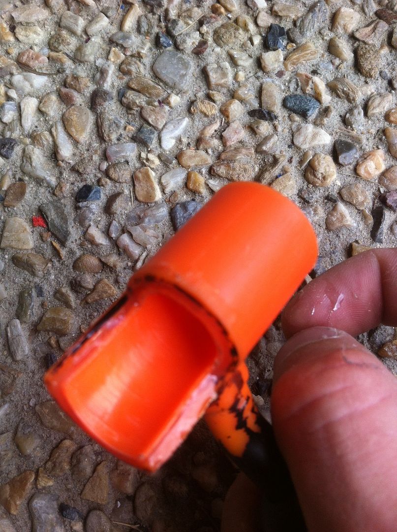
We need to cut an "air flow" hole on the underside of the breech. Basically, as the breech is closed, the 19/32" pieces you cut before are sleeved over the tee section, sealing the brass and blocking air escape. By creating an air flow hole in the 9/16" brass, you allow air to leave only through the hole, which is what allows you to direct all your energy into the breech and fire the dart.
Cut a square hole on the now exposed underside of the 9/16" brass. Make sure there is at least 2cm of uncut brass on either side, allowing you to maintain your sealed sections inside the tee.
When that is done, mark your 17/32" bolt guide in a similar manner when inside the shell. Cut another air flow hole inside it. However, this part is different. In the back part of the bolt guide, we are going to stuff a blob of putty inside it, to block off the hole and the dead space that it would create. Wait for that to cure, then slather it in epoxy glue and allow it to cure to be completely sure of no leaks.
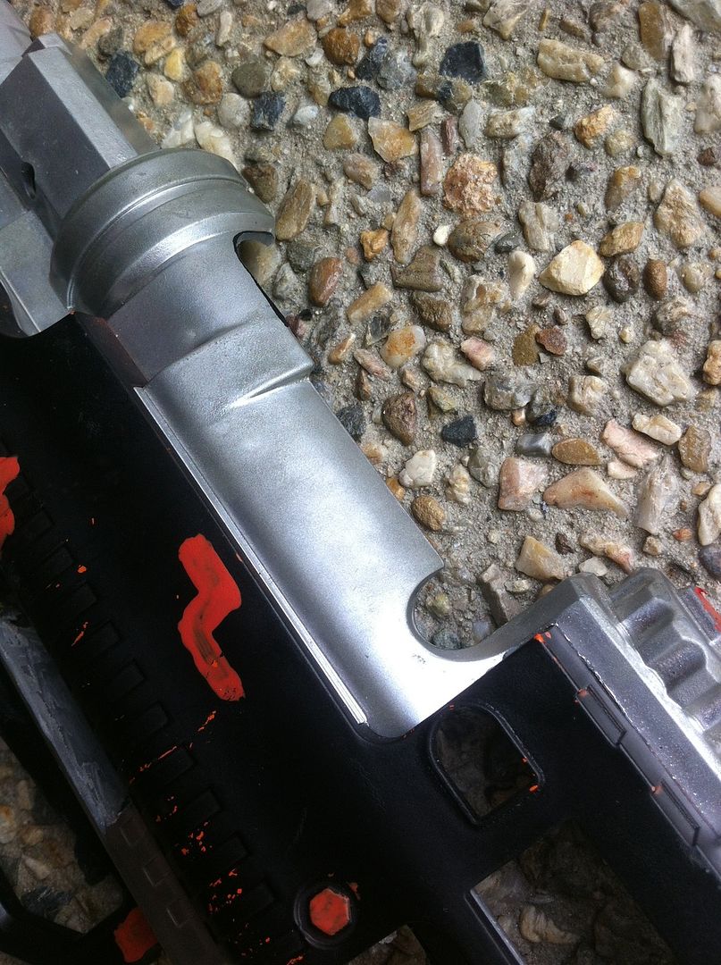
One more thing: after your bolt has cured to your 9/16" brass, lift it into the open position on the bolt guide and note which part of the bolt sits closest to the 4B tank. You may need to grind away a flat surface on this portion of the bolt to prevent it colliding with the 4B tank while traveling backward and forward.
Once that is all finished, you will have a bolt assembly that resembles this: (my tee wasn't epoxied in at this point):
Now, you pretty much have a completed bolt action breech that feeds clips.
Time to link it to an air supply. Then we will do the trigger, and we are done!
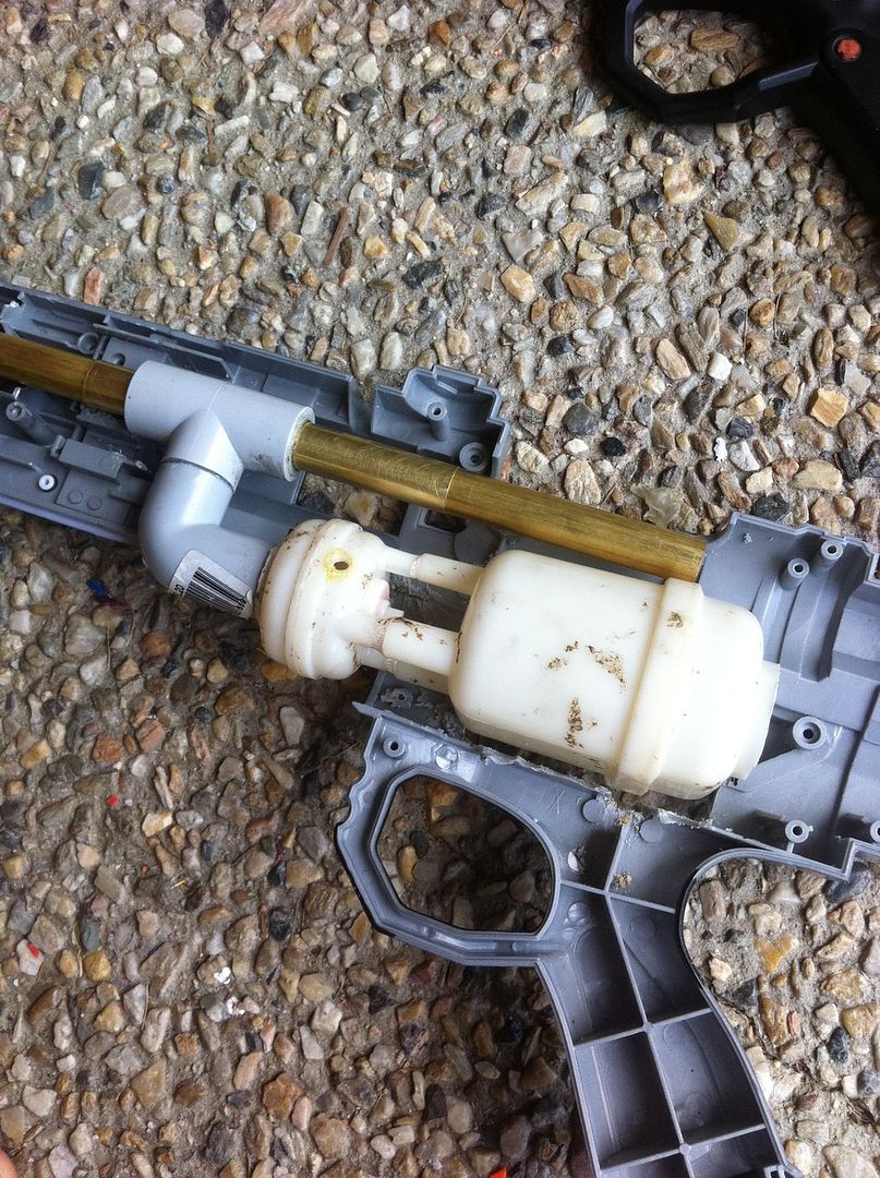
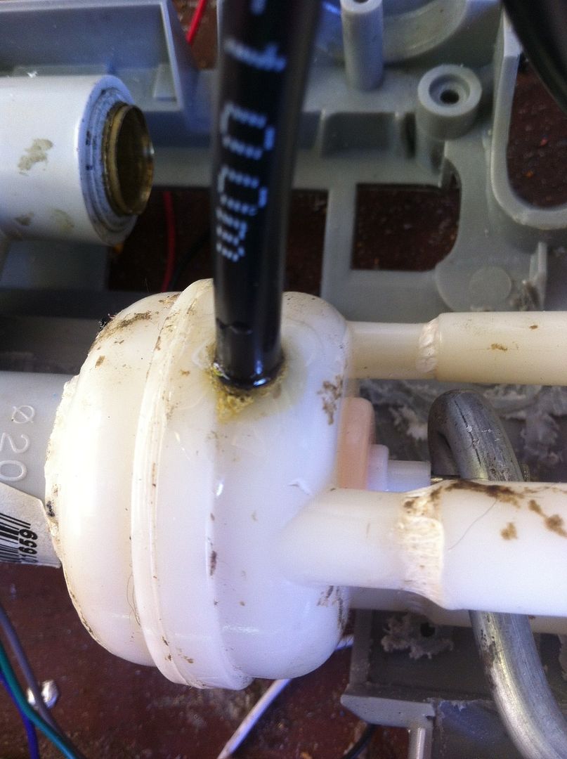
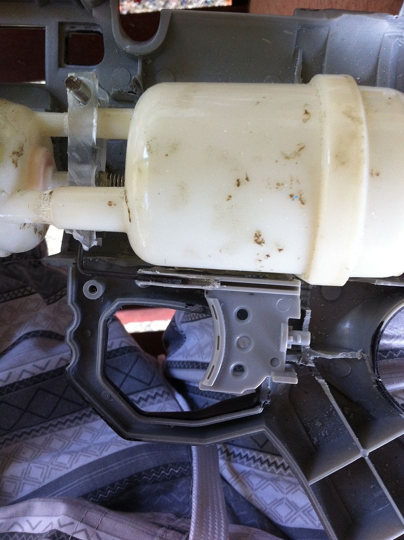
Now, here is my connection for the air tank to the air line. I received the tank with the hole like this and decided it was easier to just make do with the hole as opposed to trying to seal it and relocating a hole to where I choose to put it. I may actually seal it up properly later on and relocate a new hole to the back for the purpose of making the blaster easier to reassemble.
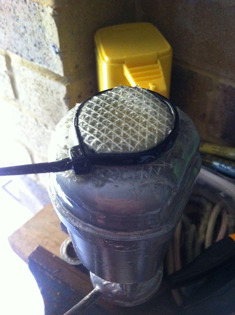
First, seal the check valve end of your tank. I did this by throwing putty inside the valve gap, then sealing it over with mesh tape and epoxy glue (does anyone see a pattern with my airblaster builds?).
Next, pick a place around the back of the tank and drill a hole for the air line to go into. I use 6mm air line, so I recommend a 6mm hole. Throw the line into the tank and seal it with liberal amounts of epoxy.
I drilled a hole in the stock connection nub, the stock connection port on the stock and a hole under the bottom of the stock to feed the air line through. I also put in a check valve to allow the blaster to remain full of air after my supply line is disconnected from the blaster, which allows me one extra shot before needing to reconnect.
All that is needed after that is to throw your air supply connection piece on the end of that air line, however you see fit (if you are using a HPA connection it will be different to my connection piece).
That gives you a complete air supply for your blaster.
Now for the trigger.
For anyone that will use a 4B tank with a lever trigger already on it, I envy you. Both 4B's for the blasters I have built with them didn't come with lever triggers. I was forced to make my own.
So here this part goes.
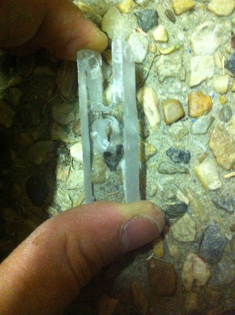
I had some 8mm polycarbonate sheet that I bought ages back, it was $30 for a 40cm by 40cm sheet. Australian products limit my availability ridiculously for things like this, but I have more than got my money's worth out of using it for projects such as this. There was no thinner option at the time, however I have gone back to Bunnings since and found thinner acrylic and PVC sheets.
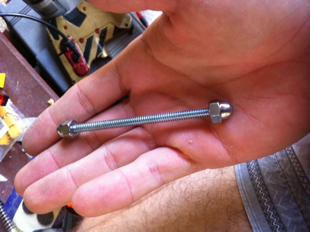
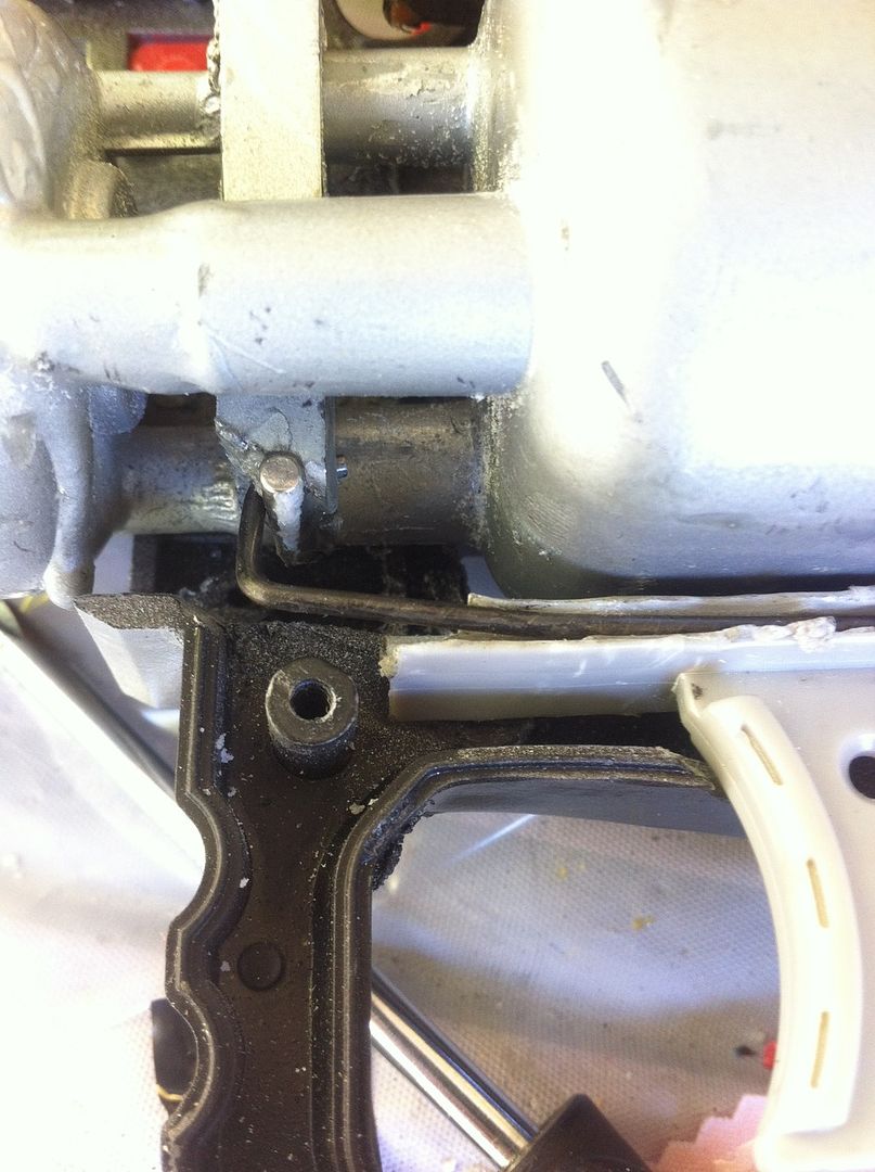
I started by simply measuring the gap under the two pipes that connect the 4B tanks. Then I measured the width of the top pipe and cut a sliver of polycarb just wider than the top pipe, and just thinner than the bottom two pipes. I also drilled two holes to allow the lever to sit comfortably over the firing pin. The result was something that resembled this:
The top two arms sat above the 4B in the shell but below the bolt section. I then ran a length of threaded rod through two holes I drilled in the shell to use as a pivot point.
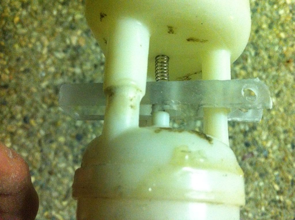
Also, I installed a return spring behind my firing pin, as the tank's stock pin was a bit sluggish to return. It's superglued on, so with a little persuasion I can remove it if I need/want.
The bottom of the polycarb got a small niche drilled sideways into it, after investigating and realising that the polycarb could NOT withstand firing pressures above 50psi.
A metal bar was epoxied to the bottom part here.
The trigger itself was the Retaliator trigger, cut down and fitted as comfortably to the shell as possible. A hole had to be cut into the inside of the trigger grip to accommodate the Ret trigger.
To connect the Ret trigger to the lever trigger, I bent a piece of BBUMB lever trigger wire I had, which can be substituted for music wire/coat hanger wire for the sake of strength. It got epoxied into place near the back for strength. After fitting, testing and refitting to make sure it was all structurally sound, this was the last part of the blaster to complete, and I got to painting.
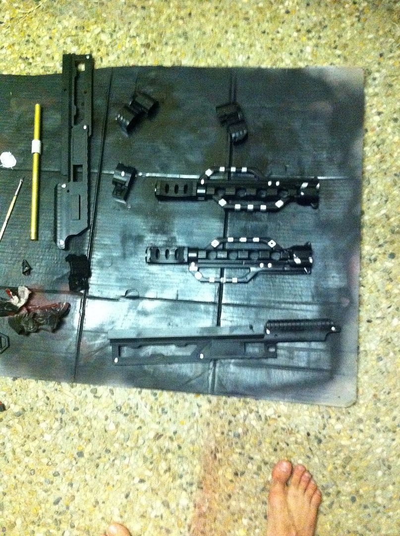
Paint pictures:
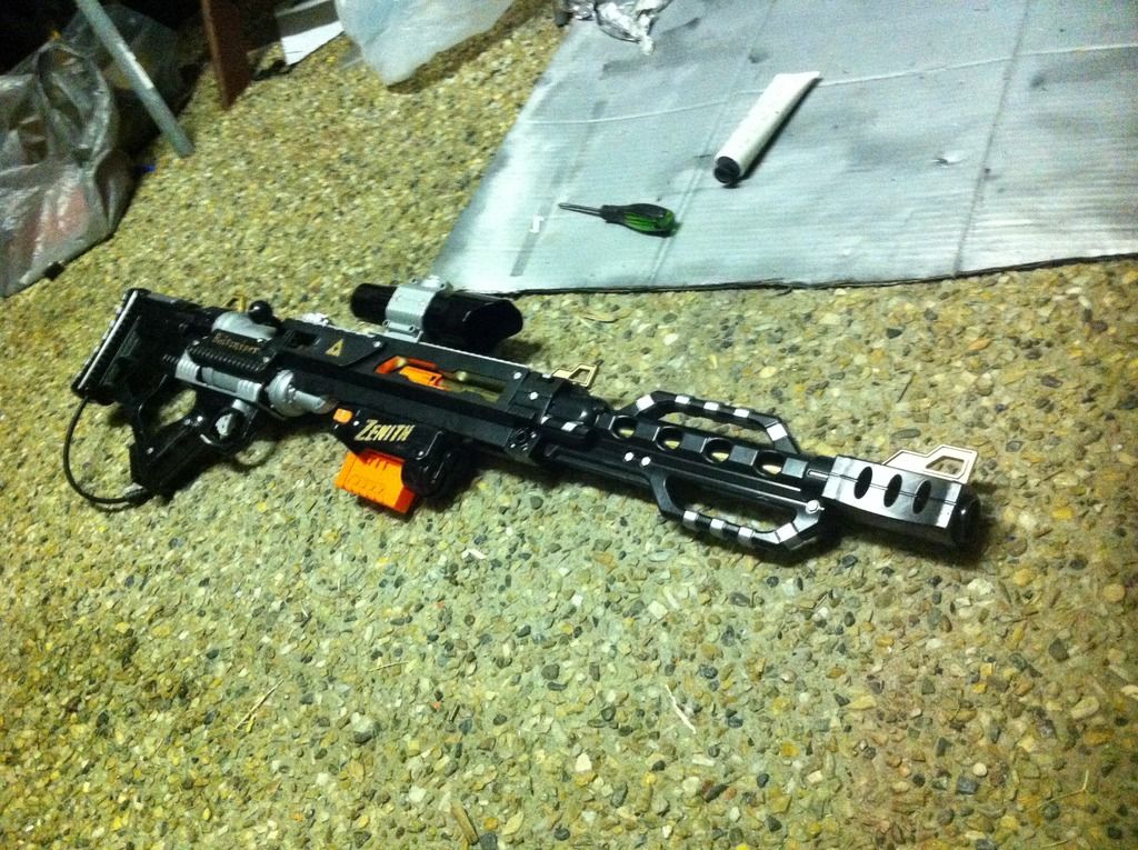
And the finished product again:
Firing demonstration coming soon.
I hope this write up was easy to follow, and if you have decided that you want to make one, feel free to fire any questions at me about it.