Jump to content


Photo

The Balistic Blast

Featuring a new trigger mechanism
homemade writeup SNAP spring

3 replies to this topic

#1 balisticjoe

balisticjoe

    Member

  • Members
  • 311 posts

Posted 15 July 2014 - 11:46 PM

*
POPULAR

For a while now I have been experimenting with the use of 1/2" aluminum u-channel as a means of a catch mechanism for a nerf blaster. After several revisions I have come up with a system that is based on the SNAP catch, but is much more repeatable with the elimination of the clothespin part of the mechanism. I believe that this new design offers a strong reliable system that applies to blasters of all types, while still being machinable from ordinary tools.

Materials

1/2" aluminum u-channel
-can be found at most home depot's/lowes, the first one needs 1 1/2', but

less than 3" for each subsequent blaster (the extra is for tool use)

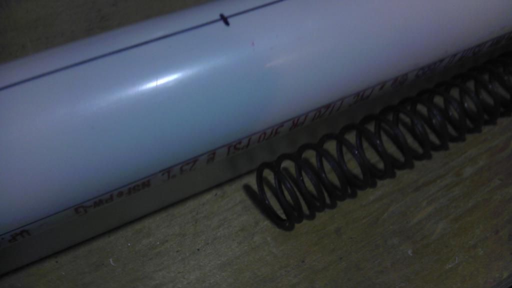
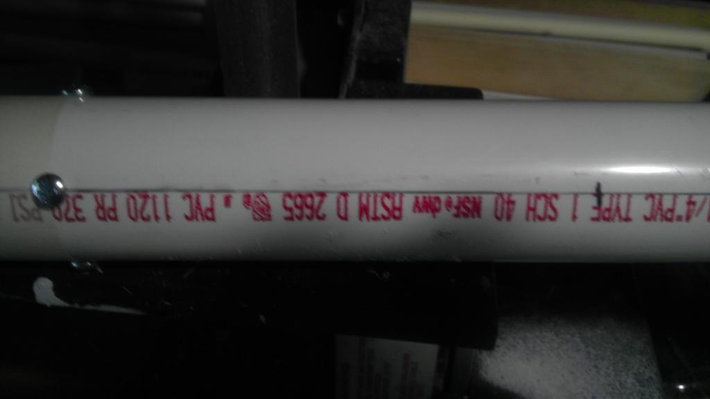
2' of 1 1/4" PVC pipe
-Yes, the 2' sections from home depot are perfect

1"x2" lumber
-you only need about 9", but a very fine handle material

an assortment of machine screws
-I prefer 8-32, but 6-32 are popular around these parts, you will need one 6-32 machine screw, you will need a tap that matches, so plan ahead

a cutting board
-Dont use your mom's, she will be very upset with you
-a good thick one from wal-mart, about $7.50, or use polycarbonate (preferred)

1/2" nylon rod
-you can get this from McMaster, if not you can use a wooden dowel from a big box store, anything 1/2", round, and reasonably strong should work

1" to 1/2" PVC reducer
-only if you want to fire darts

1 1/4" PVC coupler
-trigger mechanism mount

1 1/4" PVC tee
-Used for shoulder rest (I didn't becasue I wanted to be fancy, don't let that stop you)

1 1/2" fender washer x2

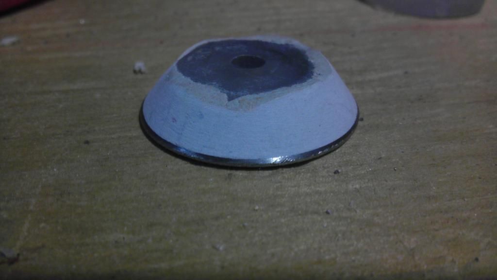
Your standard homemade blaster rubber washer
-McMaster 9562K46 you may want more than 1, just in case, or for your second one
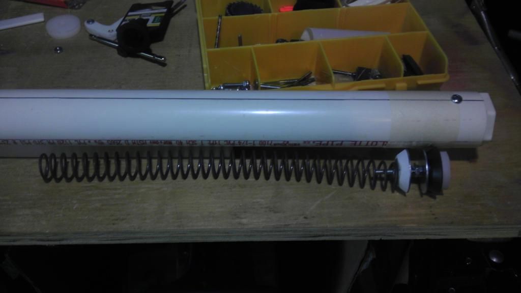
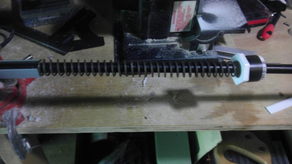
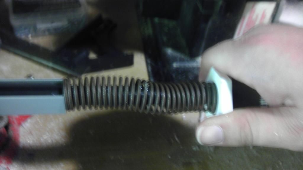
[k26] spring
-This is nerfhaven, they get used for everything McMaster 9637K26, but I will show steps to use any reasonable sized spring


Tools

Dremel
Hand drill
Coping saw
Sandpaper
Tap for your preferred screw
Round micro file (The cheap wal-mart file set is worth its cost)
Pliers, screwdrivers, etc...

That said, power tools will make your life easier and the process faster, go on craigslist, a decent drill press, a scroll and/or band saw, and especially a belt/disk sander are easy to find for pretty cheap, I got all three of mine for $100.


The trigger mechanism

I'm bad at measuring things, so to get most of the sizes right I derive them from measurements, you may notice this in the write-up. Adam Savage of mythbusters fame talks about saving time by knowing when you do and don't need to be precise, so when a sharpie is a valid method of marking cuts, don't be afraid of eyeballing stuff, it is so much easier.

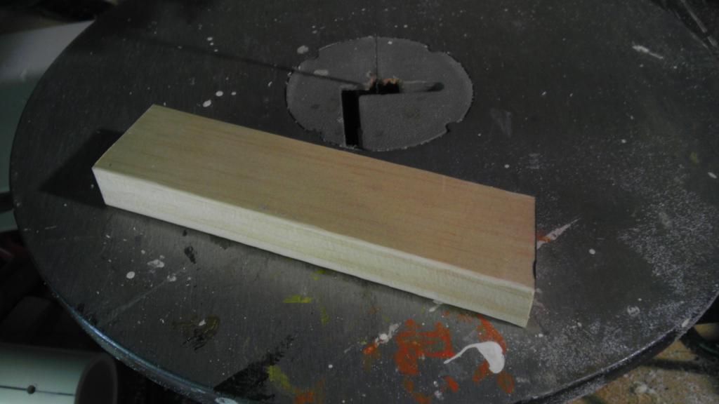
Start off with cutting a section of aluminum channel to the length of the coupler.

IMAG0334.jpg


Then, insert your cutting board or polycarbonate into the slot of the u channel, and trace around the edge. Then doodle a trigger onto one end. Don't worry about the other rectangles in the picture, that was only for a test.

IMAG0336.jpg

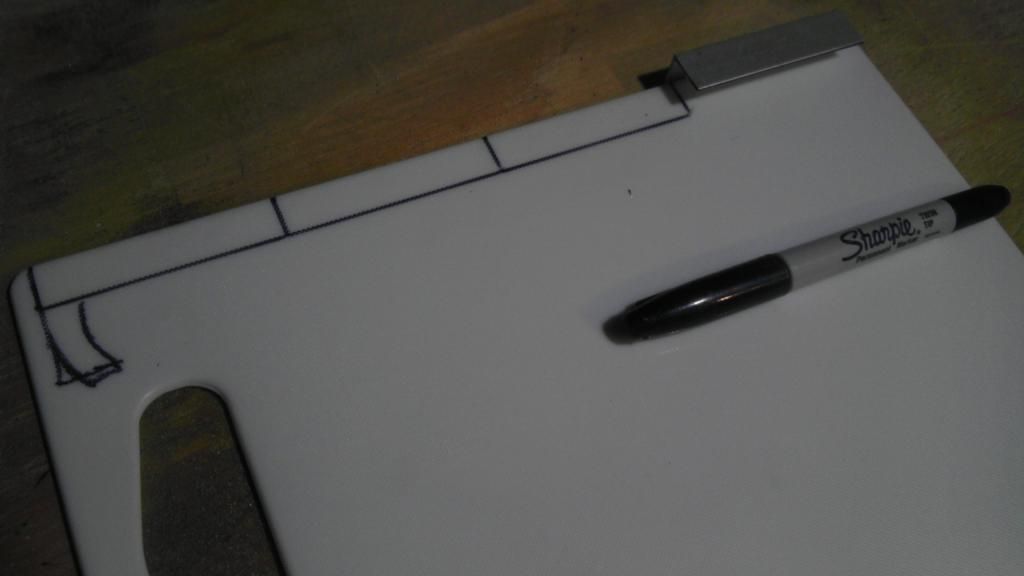
Now you need to drill a hole in the u channel, this will act as the pivot for the trigger. You will want to make it halfway between the gap and the back plate, and about the same distance from one side. The pictures will help guide you. As you can see, mine is a little lopsided, it still works fine. Tap it for your screw size.

IMAG0341.jpg

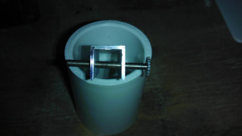
Next, we will use one of my favorite tricks, and quarter our coupler. Start by covering the coupler with one wrap of masking tape. WITH ALL THE MASKING TAPE TRICKS THE ENDS NEED TO BE IN LINE WITH EACH OTHER. That is, the tape forms a perfect cylinder around the piece.

IMAG0348.jpg

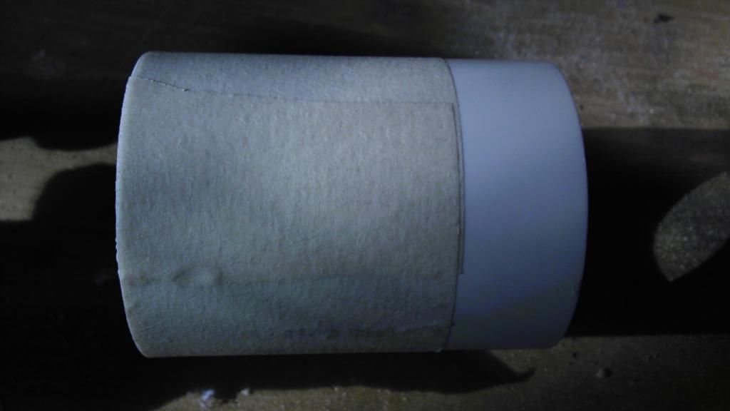
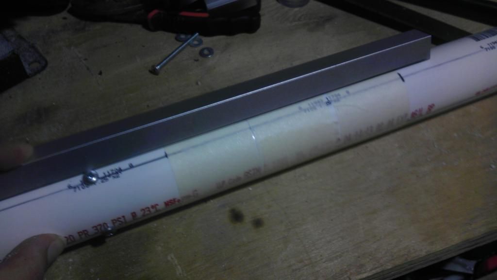
Then, cut off a 1' piece of aluminum u channel, this is now your favorite tool. Caress it if you like. Hold up the sloted end of the u channel to the coupler, with one "leg" over the seam of the tape. Because of 3 dimensional trigonometry, it turns out that where the u channel meets the coupler (or pipe) is a perfect line down the side of the cylinder. This is why it is a nerfers favorite tool.

IMAG0350.jpg

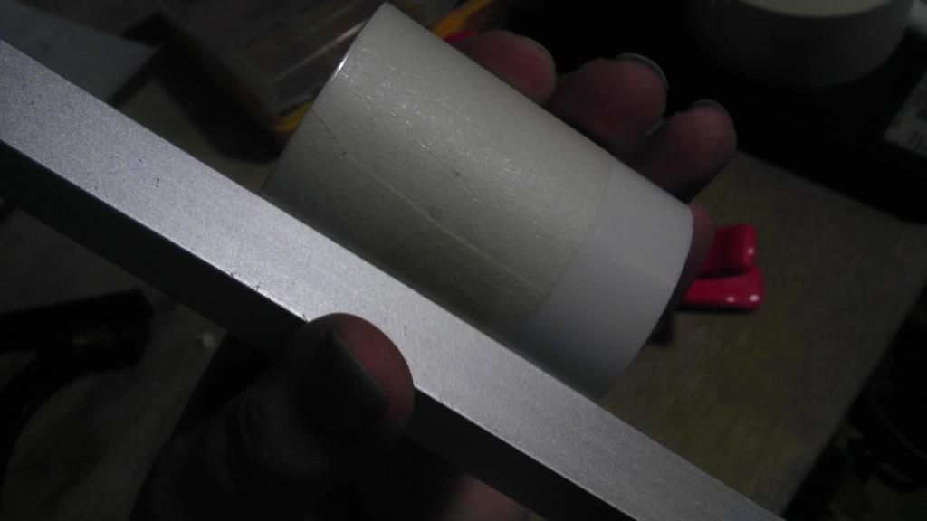
Use a knife to cut through the seam of the tape, remove the excess.

IMAG0352.jpg

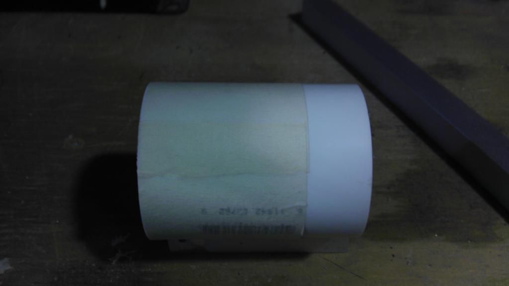
The tape, when removed from the coupler will have a length exactly equal to the diameter of the coupler. So we will remove the tape, and fold it in half non-sticky side to not-sticky side to create a seam.

IMAG0353.jpg

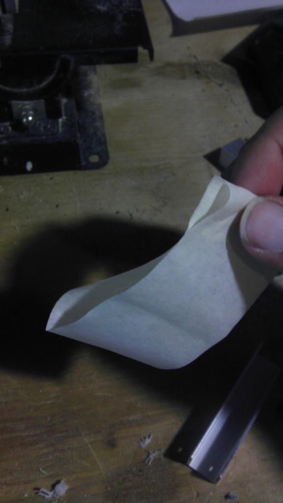
Then, use the seam to fold the sticky sides together, the tape is now equal to exactly half of the diameter of the piece.

IMAG0354.jpg

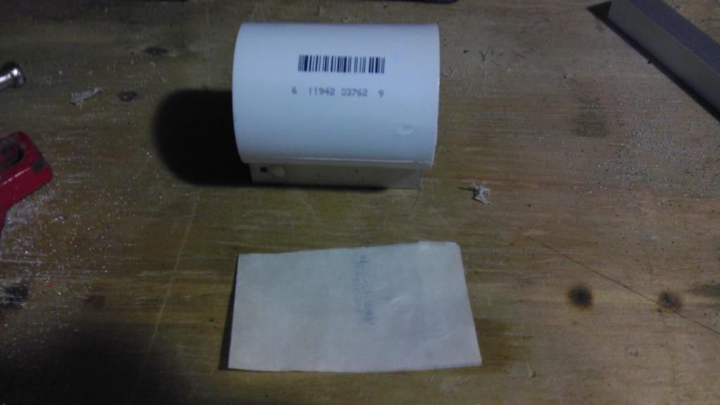
Now, fold the tape in half again. This can now be used to quarter the coupler.

IMAG0357.jpg

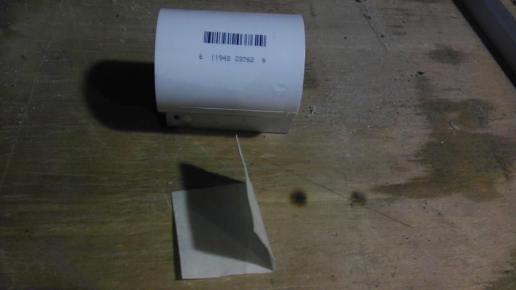
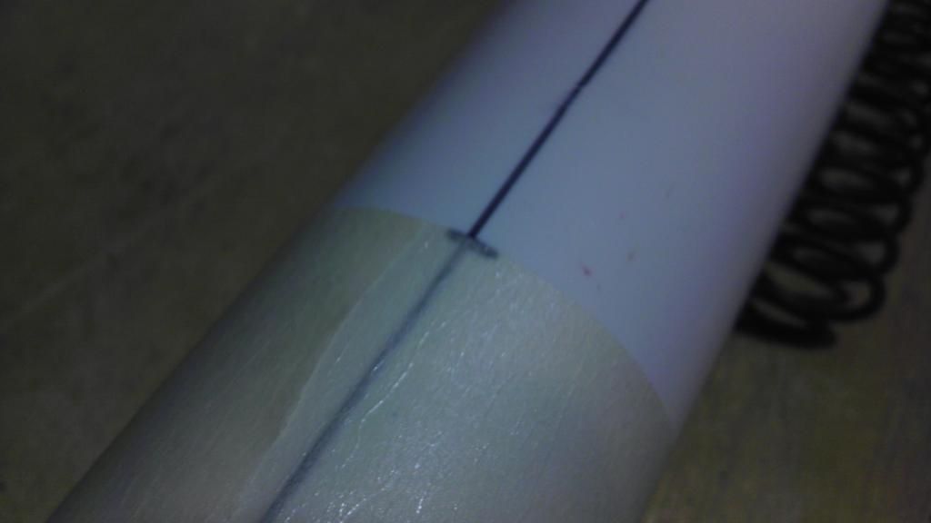
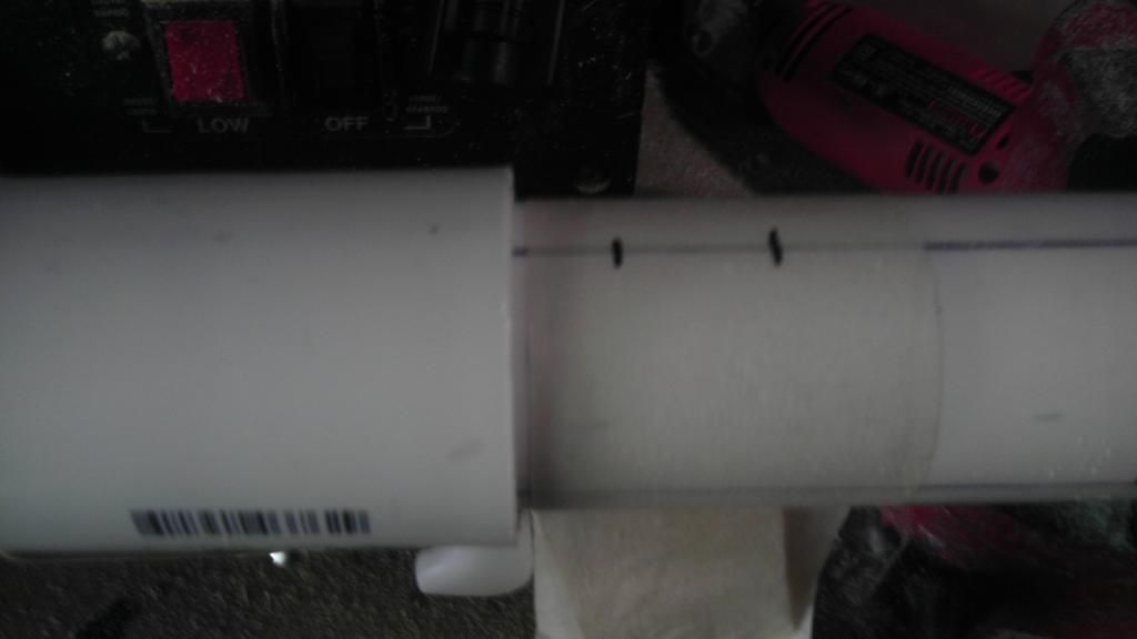
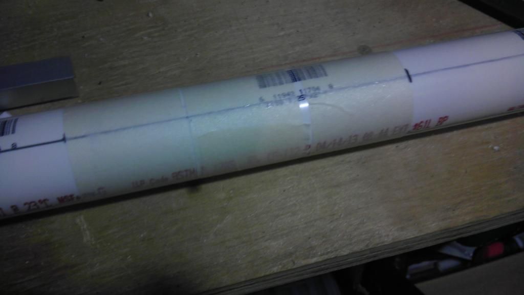
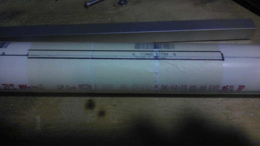
To quarter the coupler, first put a line on the coupler using the u channel.

IMAG0359.jpg

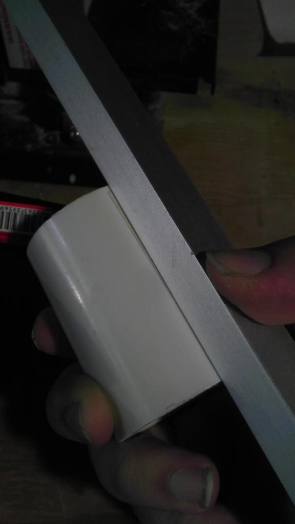
Then use the folded tape to mark each quarter along the outside of the coupler. Where the fourth the mark would go, you should line up with the line you made first, this is how you know the marks you made are exactly on quarter around the circumference of the coupler.

IMAG0360.jpg

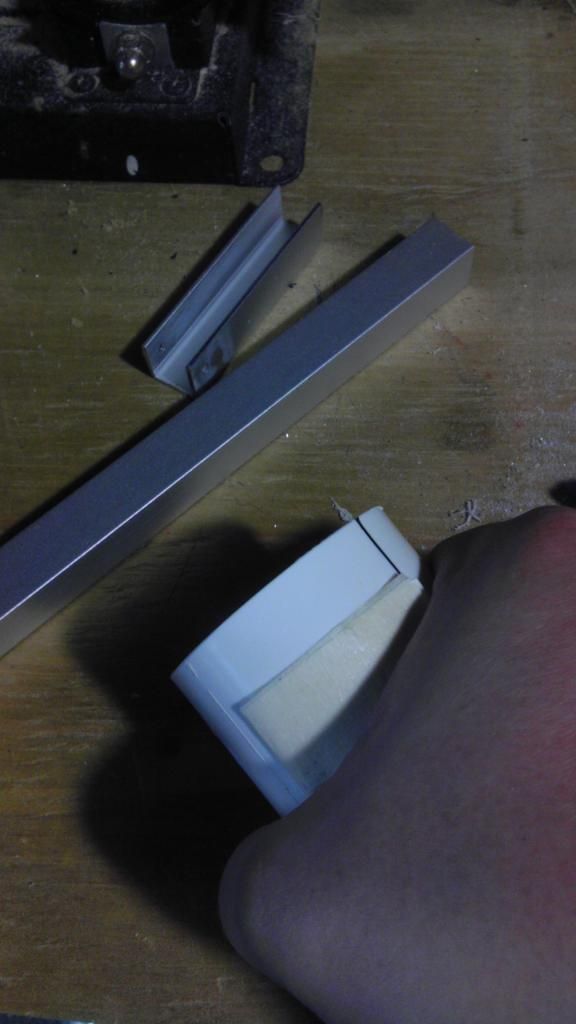
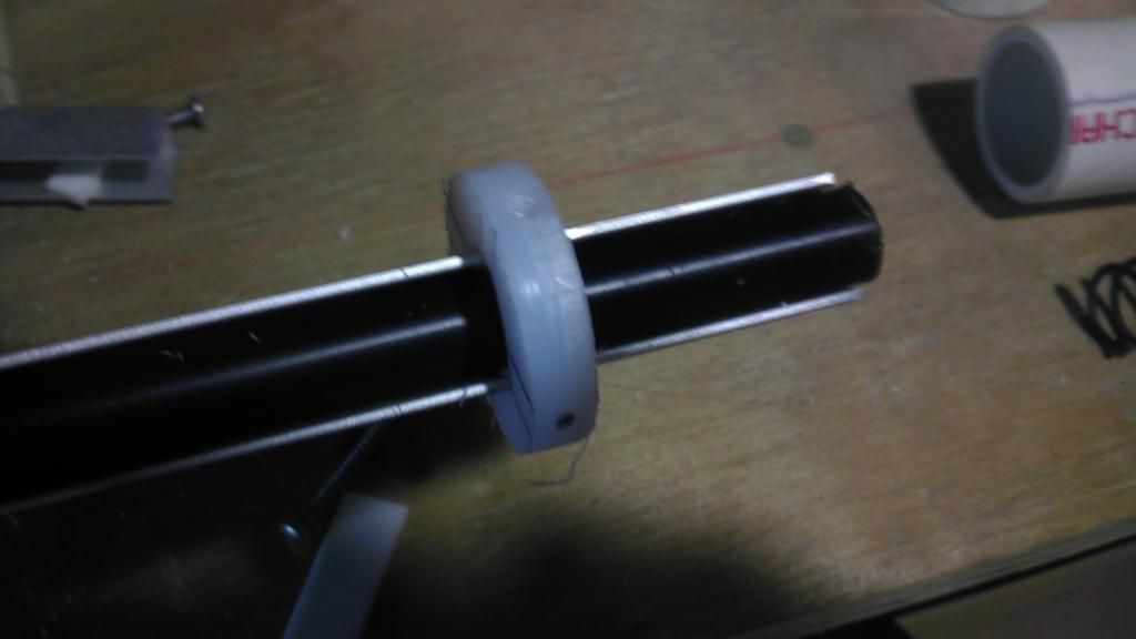
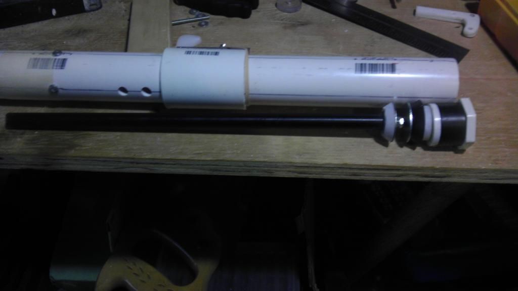
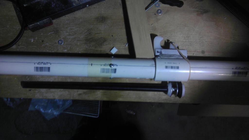
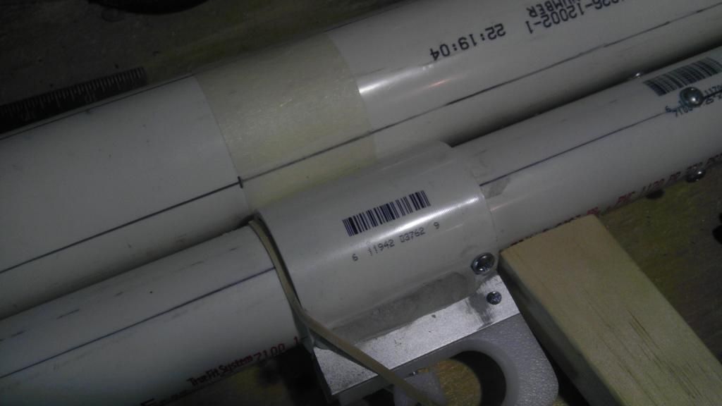
Now that we have the coupler quartered, we can attach the u channel.

IMAG0361.jpg

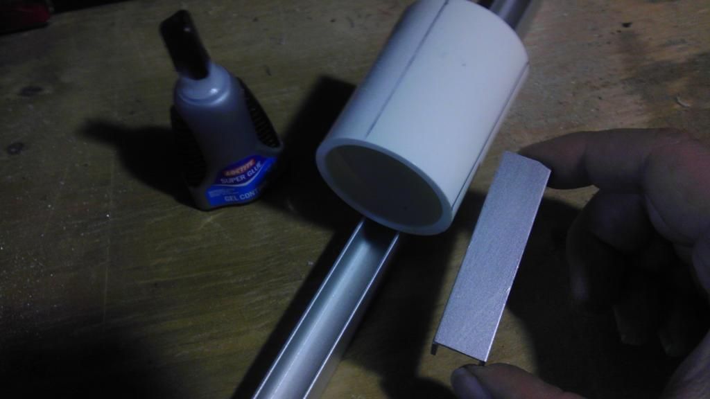
Try to line it up with one of the lines, it doesn't need to be perfect, just somewhat straight. Reinforce it with putty, and any other super adhesives you may have.

IMAG0362.jpg

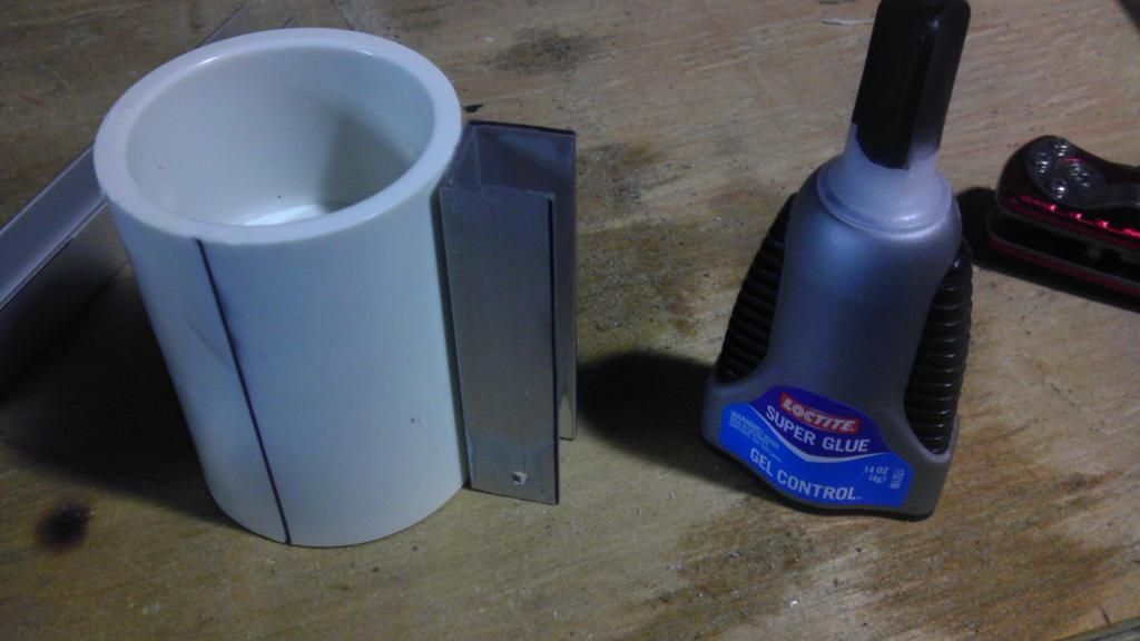
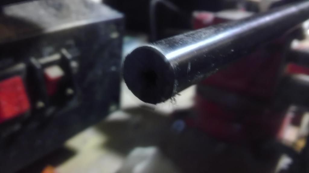
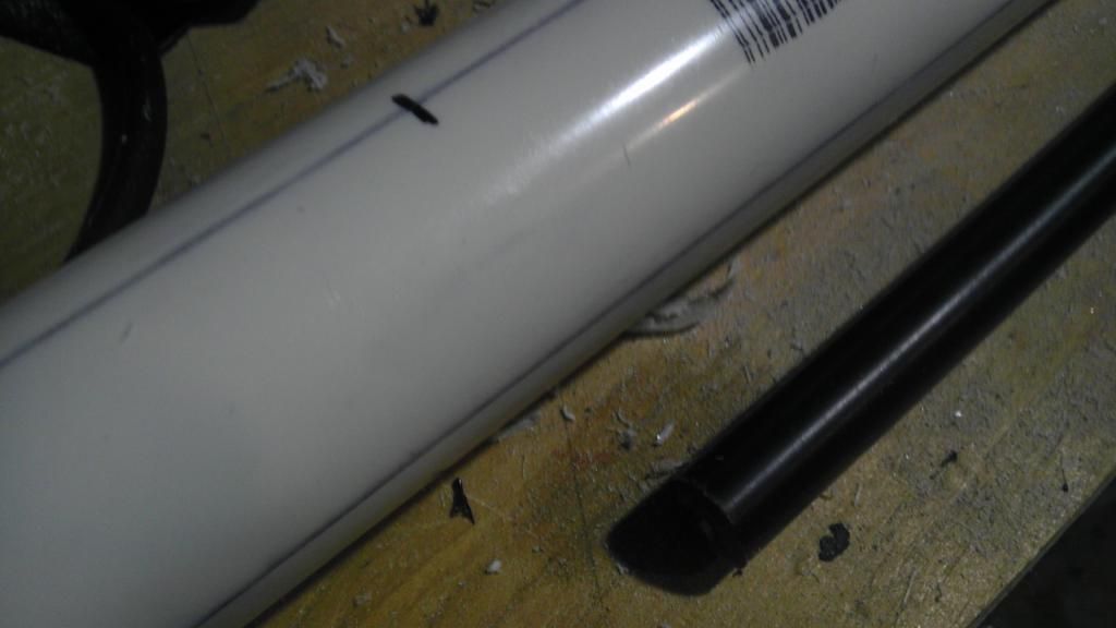
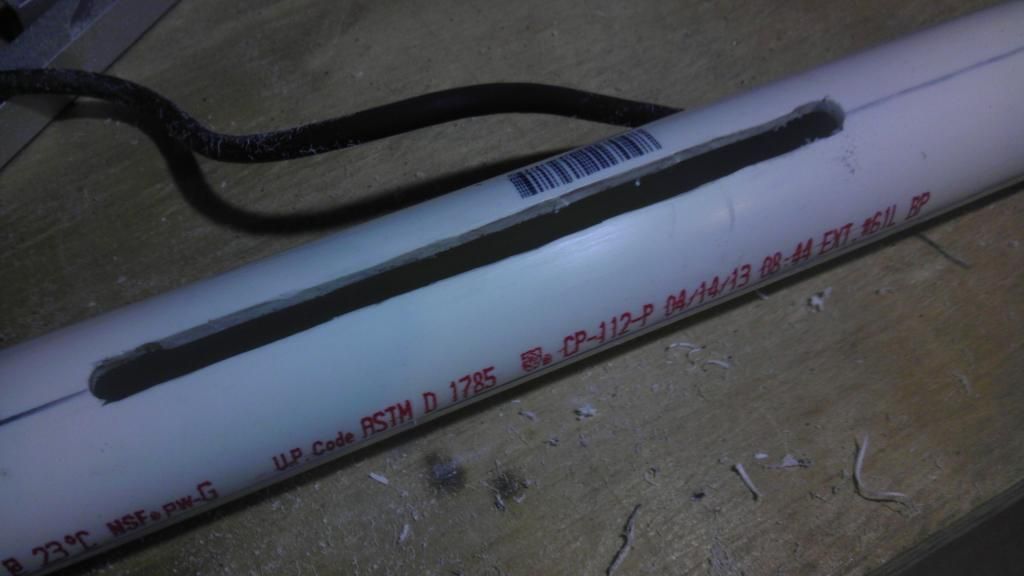
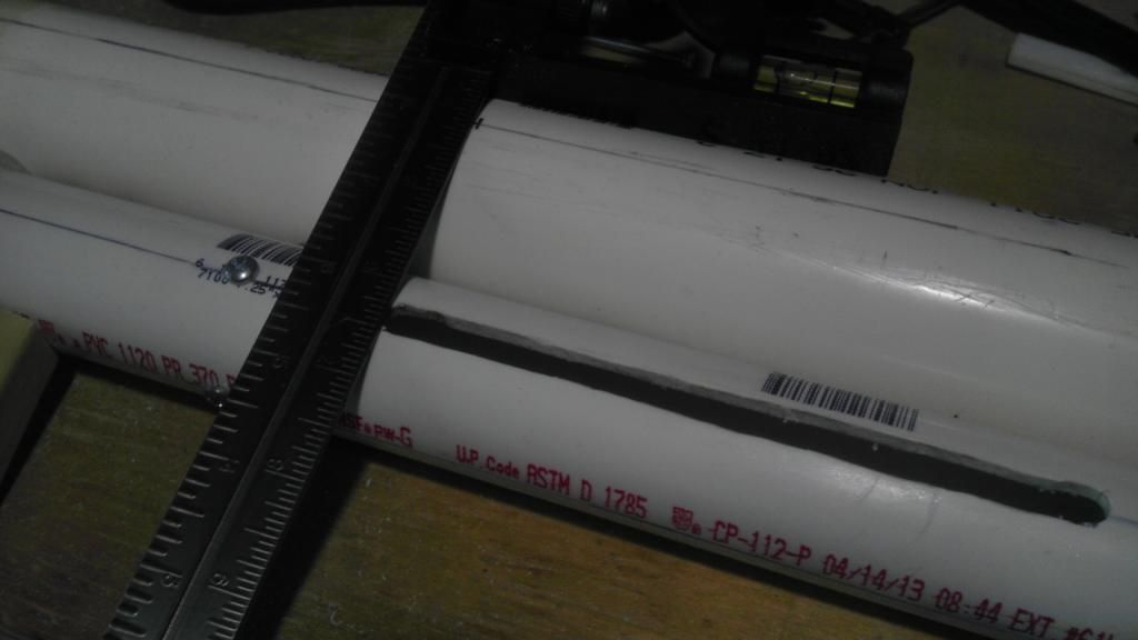
Then, you are going to want to remove this lip from inside of the coupler, just enough to slide relatively easily on the 1 1/4" PVC pipe.

IMAG0364.jpg

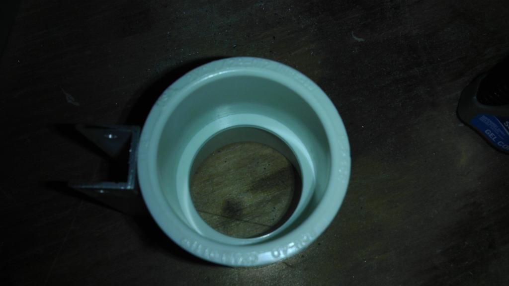
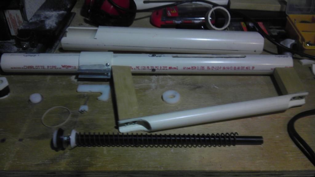
Now we are going to work on the trigger. Take the piece you traced out before, and cut it out. Hold it into the u channel, and mark where the pivot hole is, drill out the hole.

IMAG0368.jpg

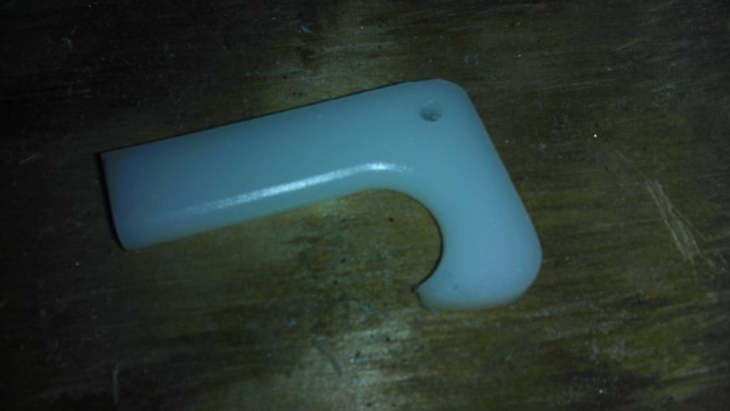
Use a small round file to open up the hole so a screw can slide through it easily.

IMAG0367.jpg

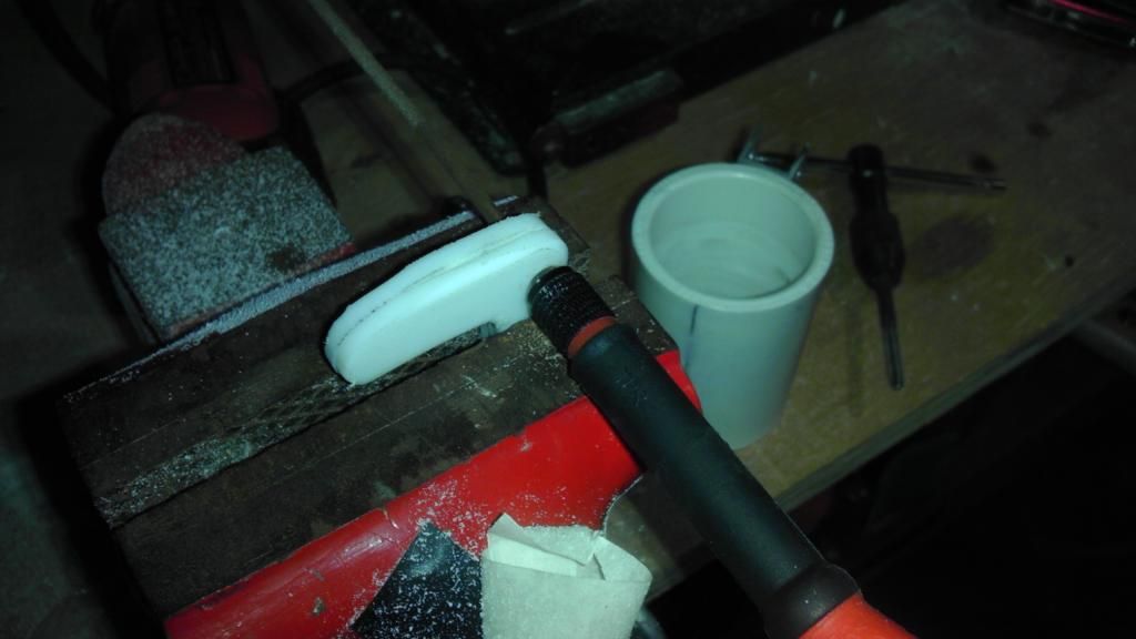
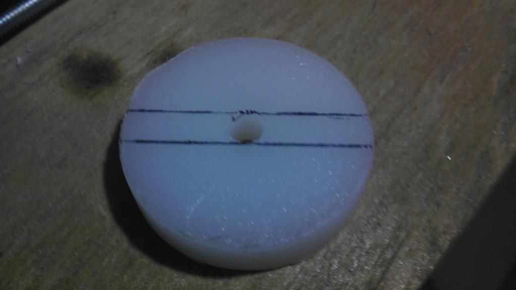
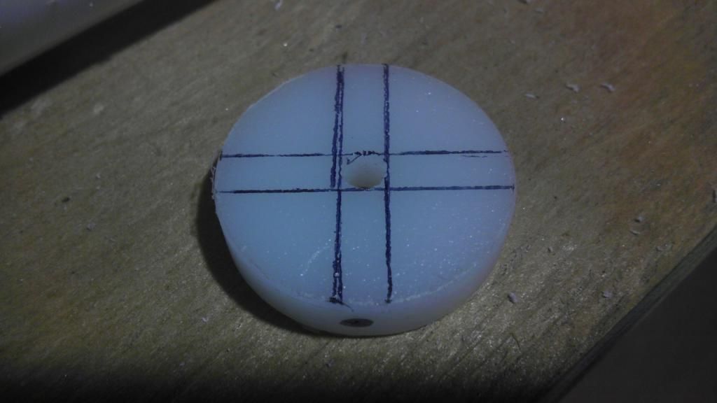
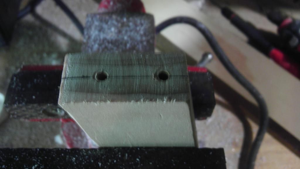
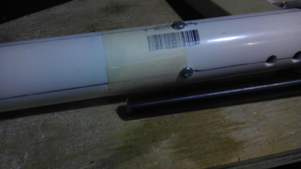
Now on the part of the trigger that meets up with the top of the u channel, make a line down the center, and drill straight down about 2 inched away from the actual trigger.

IMAG0370.jpg

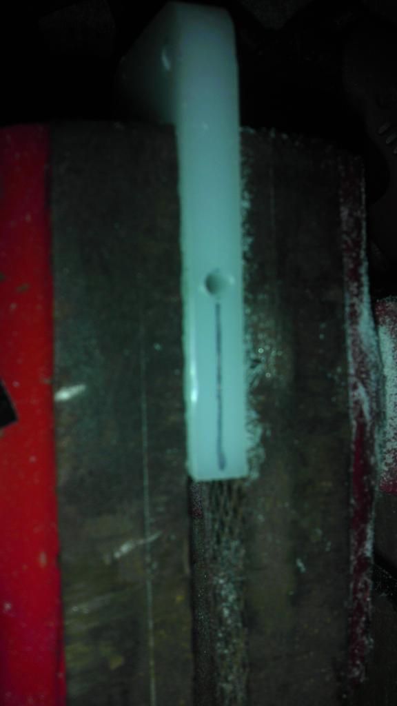
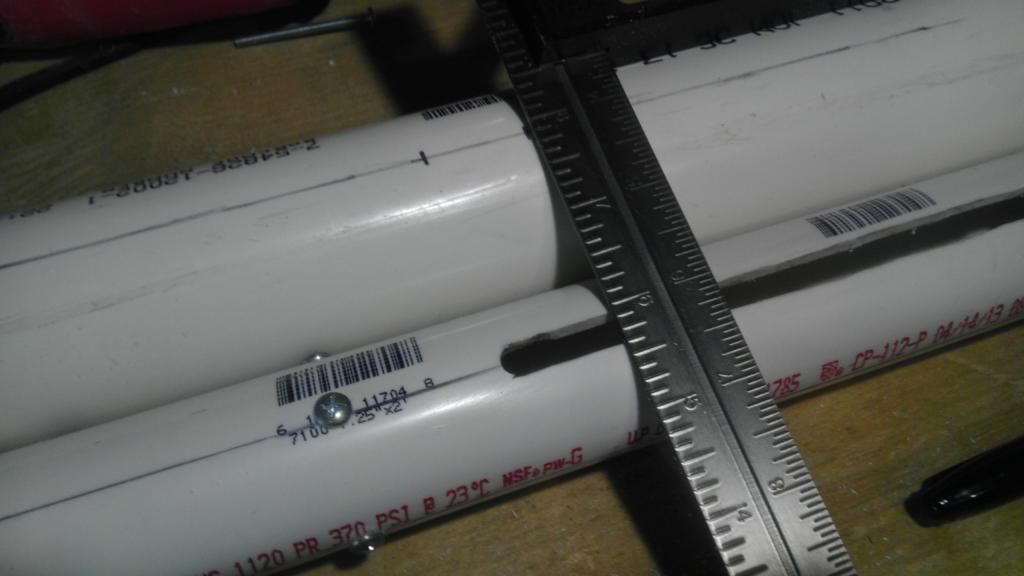
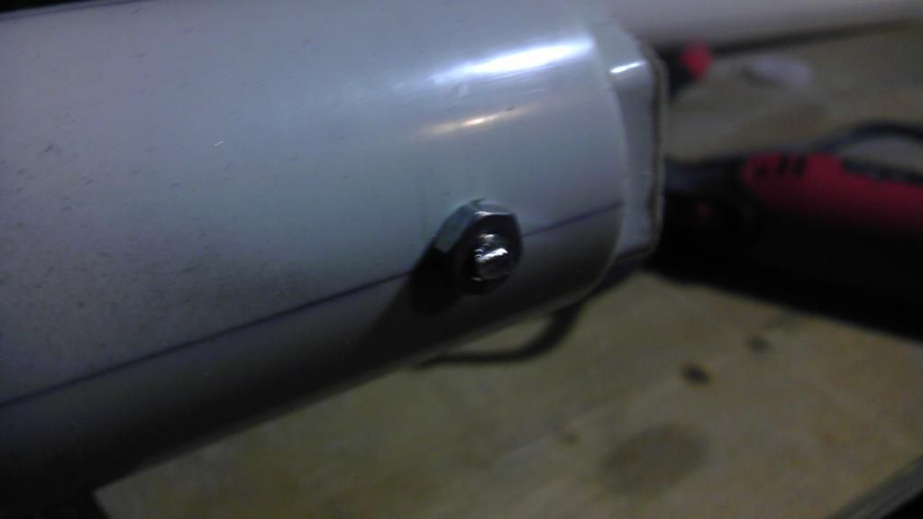
Temporarily mount the trigger in the u channel, make sure it is centered, then drill a hole through the u channel and coupler.

IMAG0378.jpg

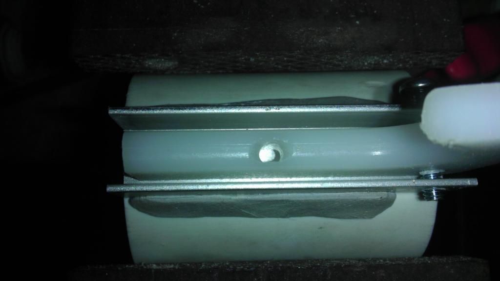
Since this hole will house the catch pin, we will need to clear some space for the pin to move freely. Do this with a small round file.

IMAG0371-1.jpg

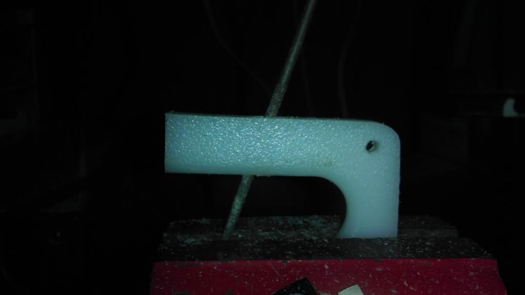
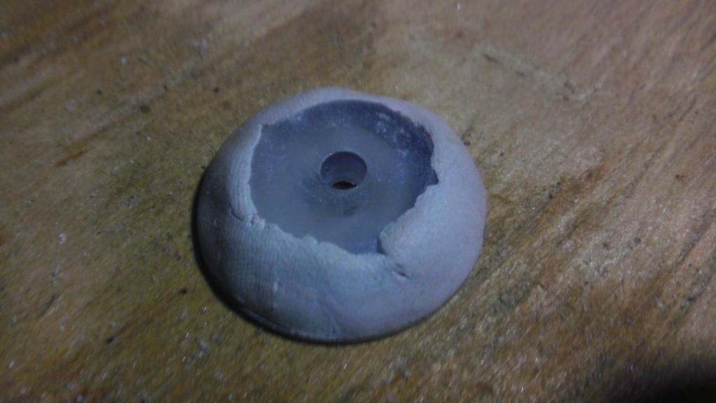
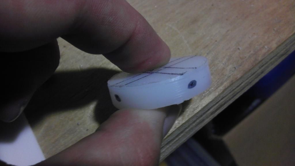
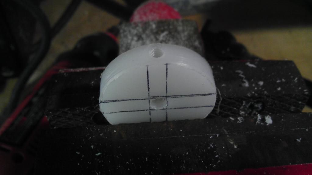
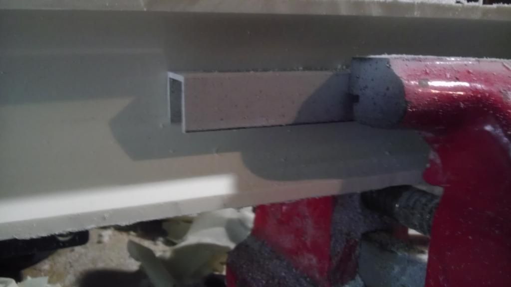
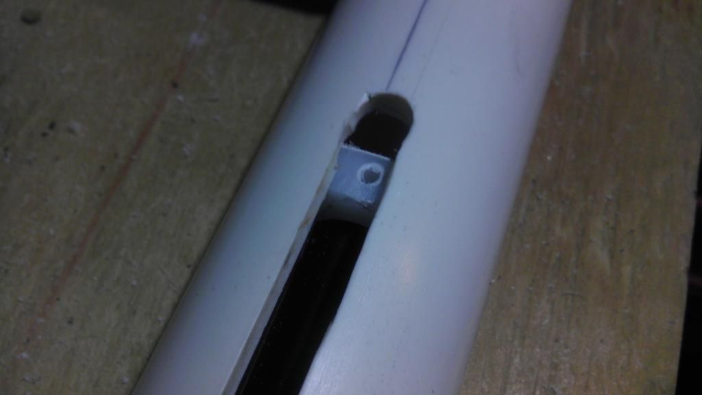
Now we will make the band rest for the catch pin. Just take a small piece of scrap plastic, and cut a small v out of a rectangle, refer to the picture for help. Be sure to round off all of the edges, you want to create a minimal amount of stress on the rubber band, shearing it will break the mechanism.

IMAG0376.jpg

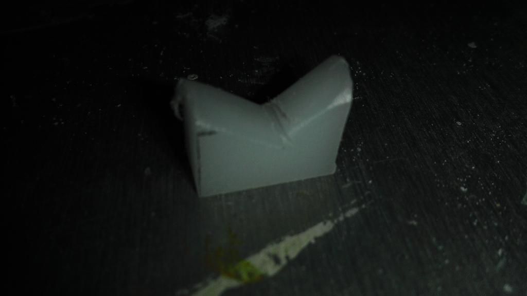
Now drill and tap a hole at the bottom of the v. Use a 6-32 here, as it will easily fit into the side of a 1/4" piece of material, with enough space for you to fudge it up a little bit.

IMAG0377.jpg

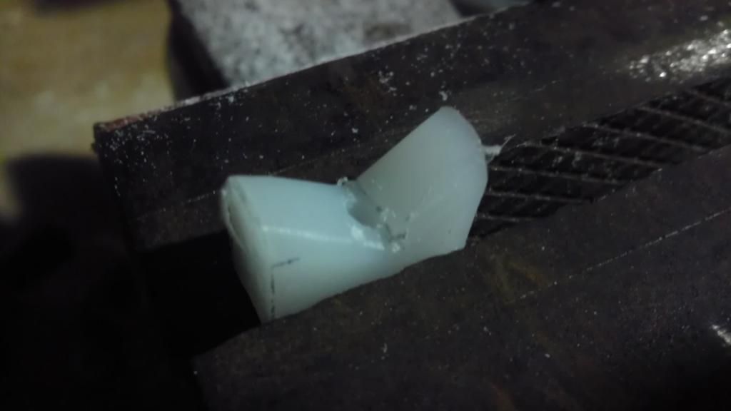
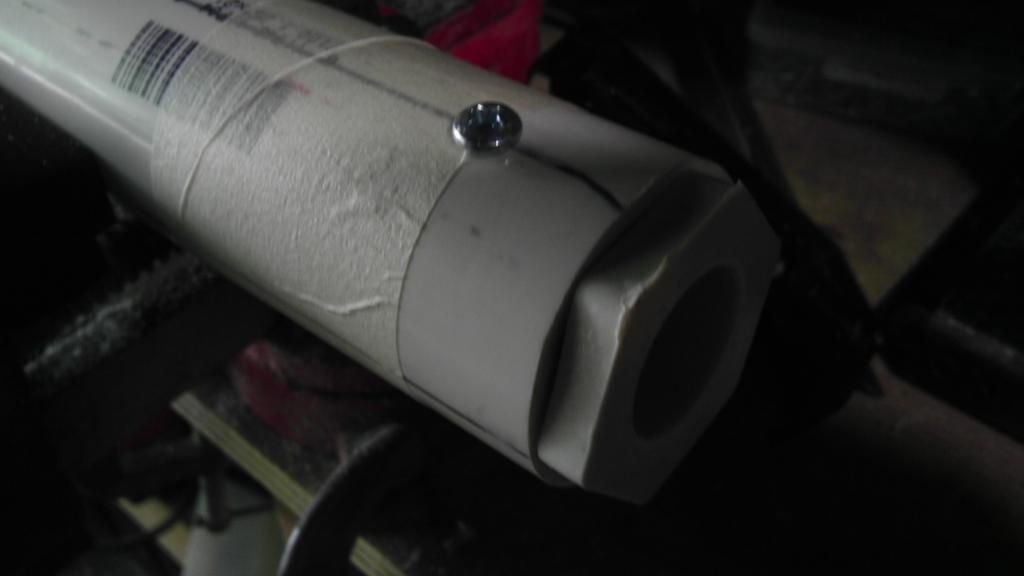
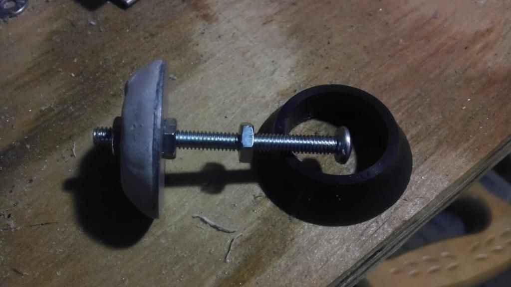
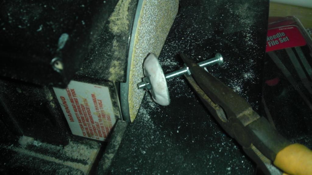
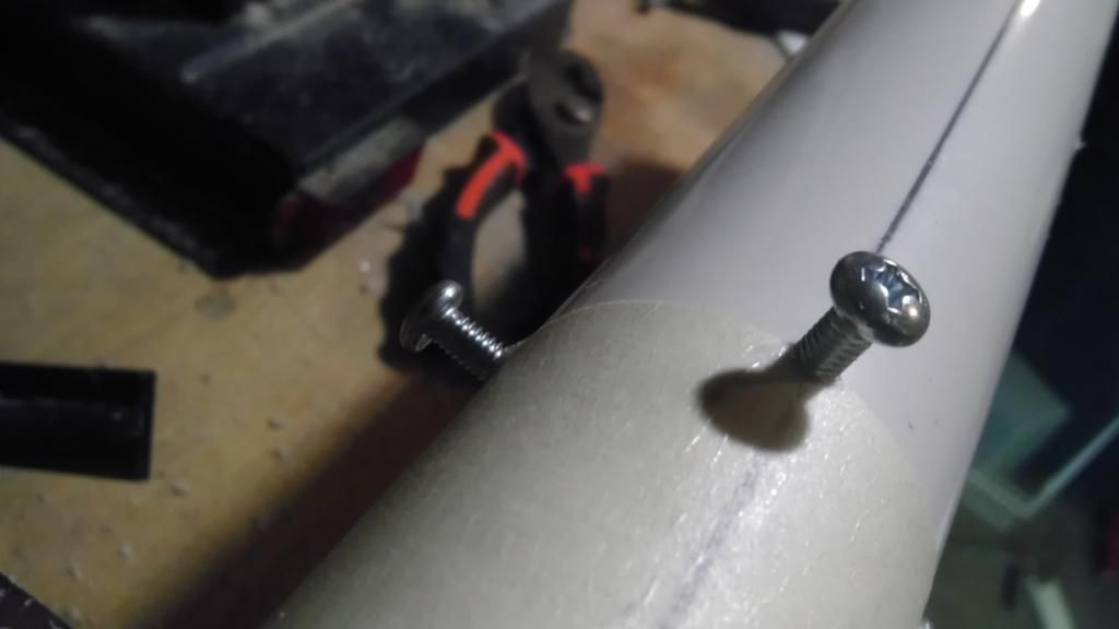
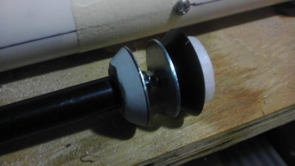
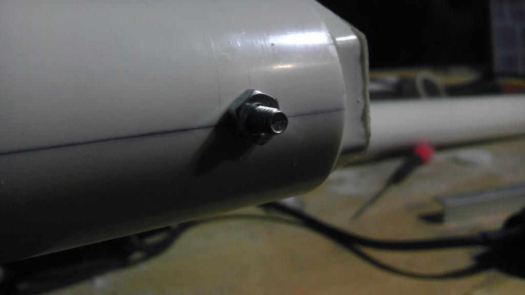
Now we will make the catch pin. To do this take a 6-32 machine screw, about 2.5" - 3" long, put a single nut on it. Using a pair of pliers to hold the nut, use a screwdriver to spin the screw while holding it against some sort of grinder, I used my belt sander. CAUTION, IT WILL GET VERY HOT. Using the screwdriver to spin it in the nut helps to create a more round profile on the screw.

IMAG0380.jpg

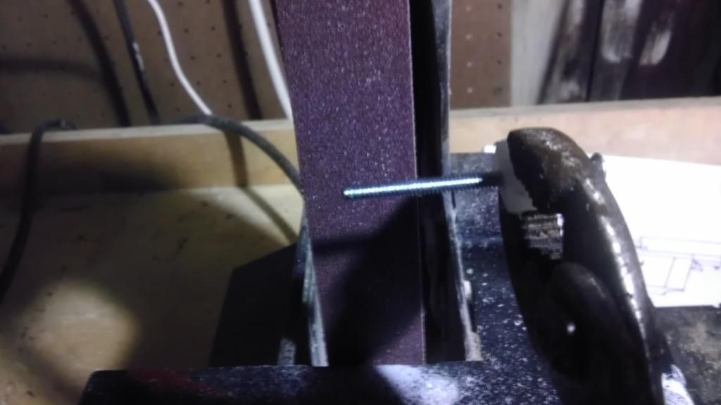
When finished, you should not be able to see any threads, and the head should be rounded off to prevent wear.

IMAG0383.jpg

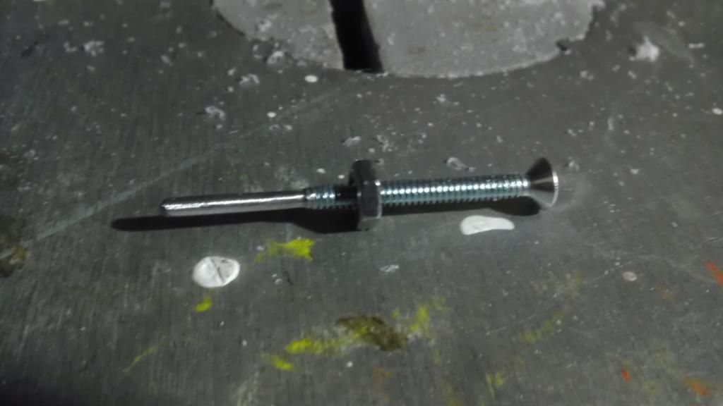
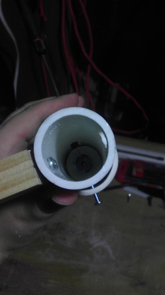
After it cools, remove the nut, and screw it into the band rest.

IMAG0384.jpg

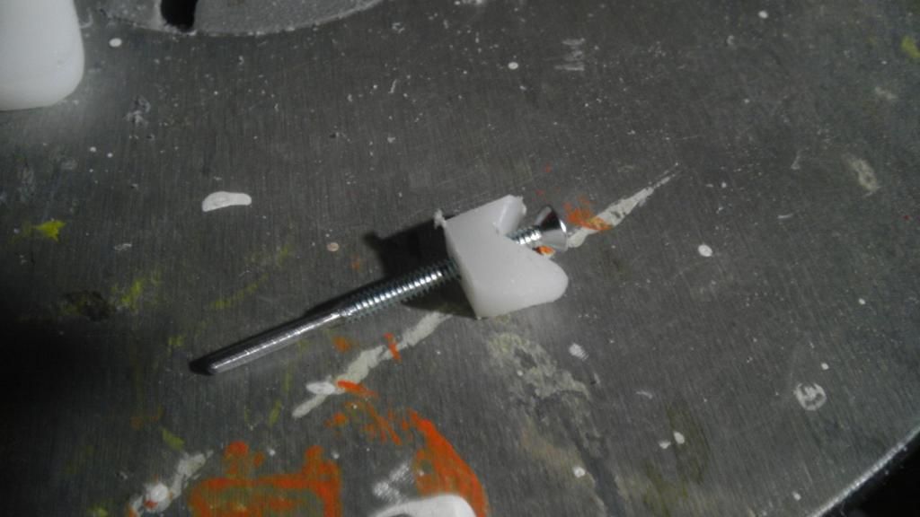
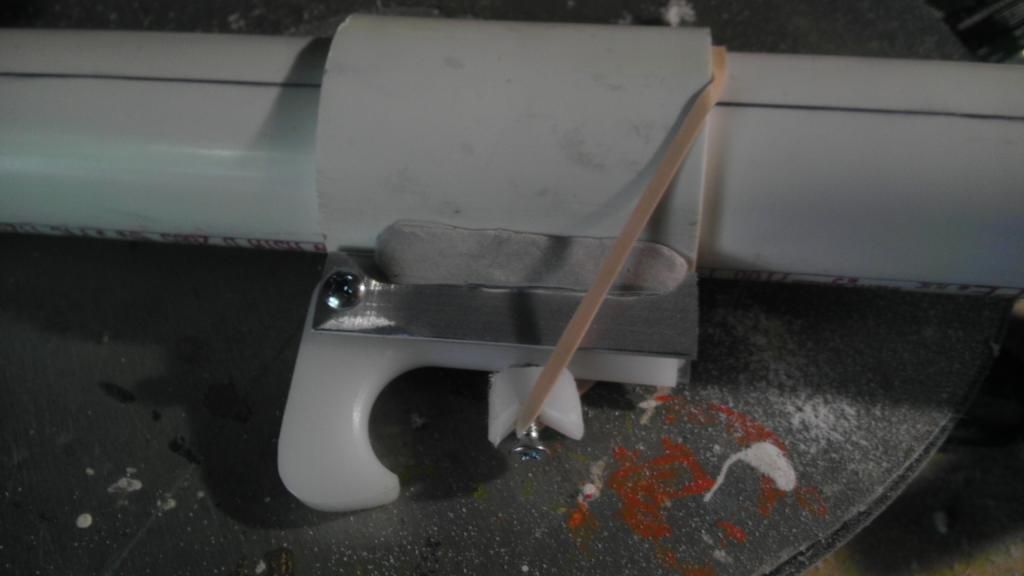
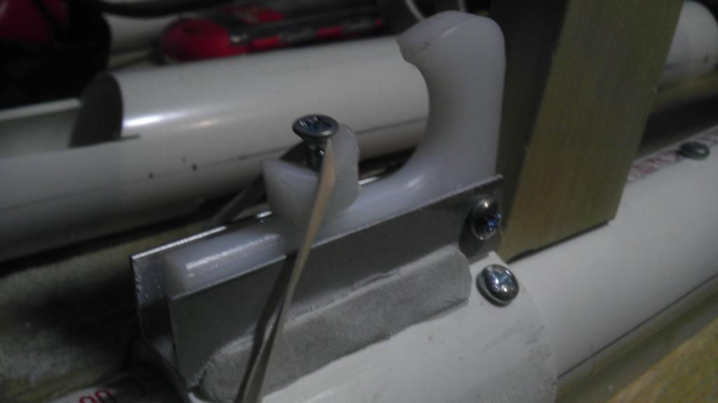
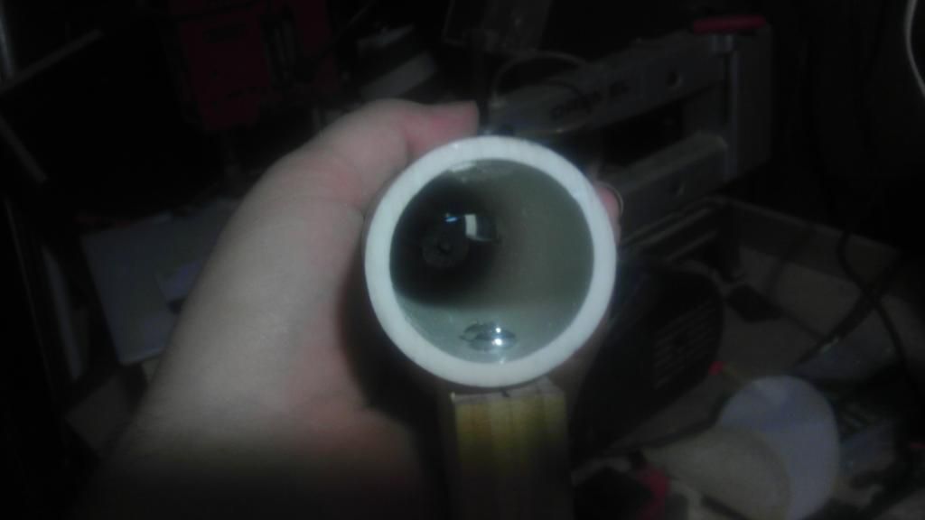
Now you can place the catch assembly into the bottom hole of the trigger. Then put on a rubber band to act as a trigger spring. This will complete the trigger mechanism.

IMAG0388.jpg


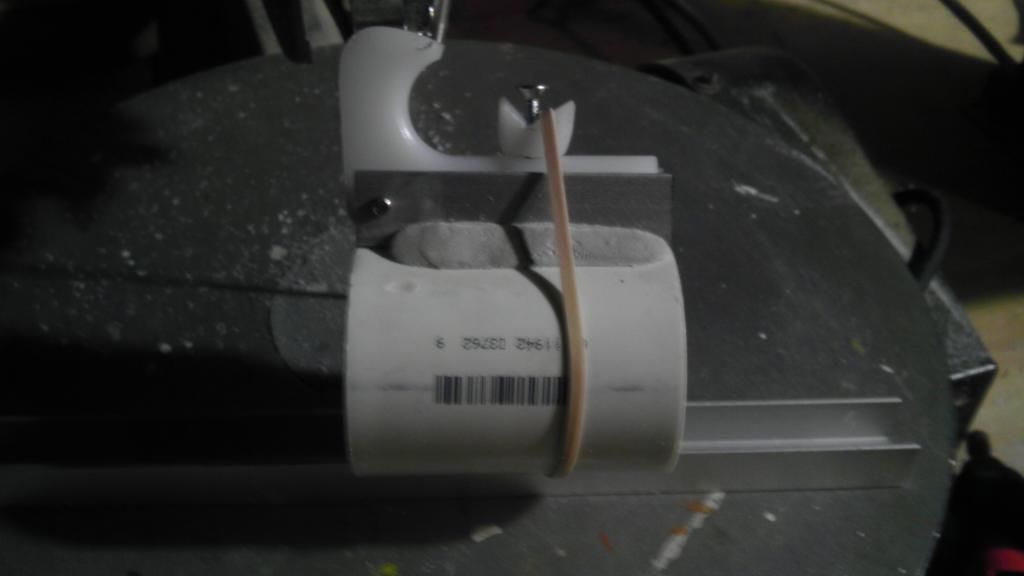
I will update this thread as soon as I can (tomorrow?) with the rest of the build. Until then I leave you with this trigger mechanism to think about. A little bit more work than a SNAP, but with notable upsides. It is fairly easy to make, and super cheap to build.

Please wait for a few minutes while I reserve Space for the rest of the posts.


Edited by Aeromech, 23 November 2015 - 02:49 AM.

  • 1
There Are No Stupid Questions, But There Are A Lot Of Inquisitive Idiots.

#2 balisticjoe

balisticjoe

    Member

  • Members
  • 311 posts

Posted 15 July 2014 - 11:48 PM

In this post I am going to build a demonstration blaster that the catch can be used for. This isn't the end-all be-all version, feel free to tweak it, design your own, or use another design adapted to the trigger mechanism. Since the mechanism is so similar to the SNAP trigger, almost all SNAP designs can be used or adapted, and there are many years of development on the SNAP offering a ton of ideas and designs.

To start off we are going to work on the barrel part of the blaster. Quarter your 2' of 1 1/4" PVC with the tape method (or another, its your blaster). To your best ability, measure how deep the reducer is AFTER the part where the 1/2" PVC fits in. It will likely be about 1/4", or more if you are lucky. Then Measure how deep the PVC will fit into the reducer, subtract the height of the hex crown on the top, add half the non-1/2" reducer height, and mark this distance on the pipe (the picture may help). put a piece of tape around the pipe, intersecting the mark, so that both ends meet, and you have a continuous line around the circumference.

Posted Image

Now drill a hole for the reducer screw on both sides, try to make it as accurate as possible.

Posted Image

Most nerfers now prefer to use packing tape for this, but I haven't ever gotten it to work, so I use electrical tape. Put a single layer toward the top of the reducer until it is just to big to fit into the PVC. Then, little by little, remove e-tape until the reducer fits snugly into the pipe.

Posted Image

Then insert the reducer into the pipe. Extend the holes from the pipe into the reducer, then tap them.

Posted Image

Now you can secure the reducer with a couple of screws.

Posted Image

Now we are going to work on the plunger head. This is most certainly not the best way to do this, so feel free to experiment with different designs. start off by taking a fender washer, and a small circle of cutting board (use a hole saw, mine is only polycarbonate becasue I had it lying around). Place the circle centered on the washer, then mound up epoxy putty around the edge to build the ramp.

Posted Image

Next, we are going to use a similar method for the trigger pin to refine the catch plate. Put two nuts onto a bolt, then the catch plate, and put a third nut onto the bolt. Tighten the plate between two nuts, and use the third to even out the ramp by holding it up to a sander.

Posted Image

I used my belt/disk sander, you can use a dremel in a vise.

Posted Image

When your done, it should look something like this.

Posted Image

Then cut out a second small circle, and a larger one. Now we can lay out all the parts of the plunger head.

Posted Image

The many nuts are used to provide a space for the catch pin to rest, any spacer will also work.

Posted Image

Now we are going to make the spring rest, it is a little tricky, but not hard. First, we need to figure out where to place it. Hold up the plunger head to the spring (in my case a [k26]), and hold it up to the blaster like so.

Posted Image

Then mark where the spring ends.

Posted Image

Next, put a piece of tape around it to indicate the same point on each side. You will also want to drill and tap holes on these points.

Posted Image

Now we need to make the spring rest. Cut out a circle of your cutting board using a 1 1/2" hole saw. Then eyeball two parallel lines that intersect with the guide hole.

Posted Image

Then make two similar perpendicular lines.

Posted Image

On the sides mark a dot in the center in between the two lines for each quarter.

Posted Image

On one of the sides, drill and tap a hole. You will also want to open the guide hole from the hole saw to large enough to fit your plunger rod.

Posted Image

Now, in order to put the spring rest into the pipe you will need your u channel tool, a small scrap of u channel, and something that it fits snugly onto, I used 1/2" nylon rod. Pinch the spring rest in between the two u channels mounted onto the rod. The spring rest should not be able to spin freely.

Posted Image

Now insert this assembly into the blaster. Move it around until you can see the spring rest through one of the holes. Then rotate it until you can see the hole you drilled into the spring rest. Now put in a 1/2" screw into the hole to hold the spring rest in place.

Posted Image

If everything went well, you should see the dots in the spring rest through the holes in the blaster. If not you may need to re-orientate the spring rest, This is to ensure you are drilling into the side of the spring rest, not the edge. If everything is lined up, gently tug the rod out of the blaster. Now use the holes you drilled and tapped earlier as a guide to drill and tap into the spring rest. I recommend rotating 90 degrees each time to prevent this process from spinning the spring rest around inside the blaster.

Now is a good time to take break. Next time I will cover the spring, plunger rod, priming handle, and final assembly.

Edited by balisticjoe, 17 July 2014 - 12:52 AM.

  • 0
There Are No Stupid Questions, But There Are A Lot Of Inquisitive Idiots.

#3 balisticjoe

balisticjoe

    Member

  • Members
  • 311 posts

Posted 15 July 2014 - 11:51 PM

Now that the spring rest is in, we can start putting the blaster together in a backwards and convoluted way that will only make sense once it all comes together.

The first step is to figure out how long the spring is going to be when compressed. If you are using a [k26] it should be the same, however due to variance in personal strength, I have included this step to optimize the compression amount. This can also be used to specialize blasters, a shorter pull for faster more rushing, or longer more power.

To figure out the compressed length, put together a rig like in the picture. it should consist of a rod running through the spring (in my case a 1/2" nylon), the spring which is resting up against something stationary (in my case, u channel chucked in my vise), and something to compress the spring (I used the 1" to 1/2" reducer).

Posted Image

Now, compress the spring as much as you feel comfortable. Pictured could be a little more compressed, but is fine. Note where the end of the spring is where compressed, the distance between where it rests and where you noted is the compressed length. Write this down, you will forget and be mad you need to do it again.

Posted Image

Now that we know how long the spring will be when primed, we can mount the trigger mechanism. Take the distance you noted, and add the height of the catch. on the bottom of the blaster, make a mark that long away from the spring rest toward the front of the blaster.

Posted Image

Now drill a small hole there, just big enough for the catch pin to fit smoothly through (smaller is better here as long as it fits, not a hotdog hallway situation). Then, with the trigger mechanism fully assembled (rubber band and all), slowly slide it down the pipe until the pin clicks into the hole. You may need to fiddle with it for a minute, feel free to remove the pin to line up the holes, its not rocket surgery.

Posted Image

You can attach the trigger mechanism with screws if you like, so long as they are toward the bottom and not deep into the blaster. I just put in two 1/4" 8-32's in right by the trigger pivot. Just make sure the trigger moves easily before you mount it.

Now we need to make our handle. I like using 1" x 2" wood, but feel free to use what you like. Cut off about 8" of wood (size may vary, I used more becasue of an extra thing I did), and on one end cut an angle that looks comfortable for your wrist. If you used the 1" x 2", sand the edges a little until it feels good in your hand.

Posted Image

From the back of the trigger mechanism, make a mark about 1/2" and 1 1/2" away on both the top and bottom, making sure the larger length does not exceed the angle cut of your handle.

Posted Image

Now drill out the two marks on the top large enough to accommodate a screw head. On the bottom drill out the two marks for a screw to go through, you may need to bore out the holes a little with a round file so the screws don't easily catch. They should be able to pass easily. Hold the handle up to the bottom, and using a thin pencil through the top holes, mark on the handle where the two screw holes are. After making sure they are center, drill out these holes and tap them.

Posted Image

Now you can screw the handle onto the blaster via the holes. Make sure not to over tighten, if you strip the threads the handle will wobble. Nobody wants a wobbly stripper.

Now we can start working on the plunger rod. The blaster is designed to use 1' of anything 1/2" in diameter. I highly recommend nylon rod from McMaster, you order it by the foot so one order is fine. A wooden dowel will also work.

Drill and tap a hole as centered and straight as you can through the end of the rod. If you are unsure, put a longish screw in it and spin the rod around, the one that wobbles less is the better one, use this for the plunger head end.

Posted Image

Attach the plunger head to the better end of the plunger rod.

Posted Image

Now we can mark where we will cut the slots. Line up the plunger rod and the reducer, this gives us the front end of the slot.

Posted Image

At the end of the plunger rod, mark on the main body of the blaster where the plunger rod ends.

Posted Image

Now, line up the front of the catch plate with the trigger pin.

Posted Image

And mark where the end of the plunger rod lines up.

Posted Image

Now use the tape trick to line up the marks on both sides. I put an extra piece of tape in the center to make marking easier.

Posted Image

To mark the slots, I like to use a piece of aluminum u channel and use the screw head from the spring rest to make a straight line for the slots.

Posted Image

The result should be something like this on each side.

Posted Image

Now us a dremel cut off wheel to cut out the slots. Just take your time and try to make them as straight as possible. Be sure to wear a dust mask while doing this, it turns out PVC dust and human respiration are not friends.

Posted Image

Now we can make the final major component, the pump handle. I will be the first to admit, this is not the best way to do this. There is a chance you can cut your cheek when pumping your blaster, however it is very simple to make and very functional. So just practice your coordination, and please don't sue.

The first step is to figure out the length of the 2" PVC pipe we need to cut. Start by quartering a length of 2" PVC pipe. Then mark your hand, a good grip on a pump handle is about 4" give or take. Then add the length of the slots to give room for it to slide for me it was about 10". This is marked by the tape.

Posted Image

Now, with the mark lined up with the front of the trigger mechanism coupler, mark the the 2" pipe in line with the slot you cut earlier. Drill this mark on both sides.

Posted Image

About 1/2" to 1", whichever you prefer, mark on the line of the pipe. This will be where you cut the pipe.

Posted Image

With the pump handle lined up, mark on the pump handle where the front of the main body is.

Posted Image

Using a piece of u channel as a spacer, mark the 2" pipe to give space for screws to go in later.

Posted Image

Now, using the picture as a general reference, use a dremel cut off wheel to cut out the pump handle shape.

Posted Image

Clean it up a bit, round off the corners, soften up the edges, make it look pretty.

Posted Image

A trick I found was to use a piece of u channel to give a better grip in a vise.

Posted Image

Now we should have all the components of the blaster ready for assembly.

Posted Image

Start by putting together the trigger, if you happened to take it apart earlier. Make sure the rubber band is forward of the coupler.

Posted Image

Sadly, I did not get a picture of the next step. Take your plunger rod assembly, and lubricate the plunger head (I use some really bad faucet grease, get the best you can). Place the spring on the plunger rod. Now, push the plunger rod into the blaster, a trick I found was to point the blaster downward, apply pressure with my fingers up against the spring rest, and sort of bounce it in while tilting the blaster slightly. Once the plunger rod is fed into the blaster, use your u channel to push the plunger rod all the way back until the catch engages. If you cant get it past the catch, try unscrewing the catch pin a little. Mine went in easy the first try. Leave it in the primed position for the rest of the assembly.

Now, put the reducer in the front of the blaster and lone up the holes. Put a machine screw through the entire blaster with a nut on the end.

Posted Image

Cut off the excess screw to allow the pump handle to slip on.

Posted Image

Now using a piece similar to the spring rest, but with only two screw holes, feed it onto the plunger rod in the back and line up the holes with the slots.

Posted Image

Now slide on the pump handle. If you are having trouble sliding the pump handle on the trigger mechanism, sand it down a little, or try putting a little bit of lubricant on it. Put two screws through the pump handle into the pump slide. I used a small file through one hole to help align the other.

Posted Image

With both sides screwed in, the pump handle should move freely forward and back. For now, put it in the forward position. This should expose just the plunger rod in the back.

Posted Image

The final step is to screw a circle of plastic onto the back of the plunger rod. I used a scrap of polycarbonate, but a piece of cutting board will also work.

And you are done. Congratulations.

Posted Image

I think they call this a money shot.

Posted Image

Posted Image

Edited by balisticjoe, 21 July 2014 - 11:01 PM.

  • 0
There Are No Stupid Questions, But There Are A Lot Of Inquisitive Idiots.

#4 ultranewt

ultranewt

    Member

  • Members
  • 35 posts

Posted 23 July 2014 - 08:50 AM

Cool blaster, with the adjustable catch pin and all.
  • 0


Also tagged with one or more of these keywords: homemade, writeup, SNAP, spring

0 user(s) are reading this topic

0 members, 0 guests, 0 anonymous users