Jump to content


Photo

Crankbow, FINALLY!

A project for the ages with a really poor writeup.

18 replies to this topic

#1 Exo

Exo

    Member

  • Members
  • 391 posts

Posted 29 August 2012 - 06:46 PM

I finally got around to writing this writeup. I hope you enjoy.

INTRODUCING, THE FIRST HOMEMADE, CRANK-POWERED, BOW ARMED, AUTOMATIC NERF BLASTER!


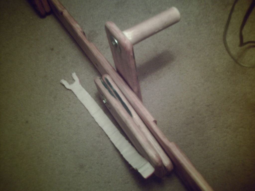
As you can see, it is quite large and bulky. However, being the first of it's kind, this is expected. I may eventually make a much smaller, bullpup version. The basic mechanism will remain the same, as it has been proven, but the dimensions will be shrunk, and the orientation will be changed up so that this can actually be shouldered.

This is not an explicit writeup. I expect you to have basic woodworking skills, knowledge of how to apply basic scaling, knowledge of how to make a set of bow arms and an accompamying HAMP or LAPM, and enough intelligence to stitch fabric without raping your fingers. Here goes.

MATERIALS:
Lots of wood, appx. 1/2" thick, 4" wide, 4-5' long. I'd say 4-5 of these planks.
A wood dowel, however wide you like, this will be your handle(s).
Wood screws, just buy a box.
Stuff to mount the HAMP/LAMP w/bow arms to the crank mech.
Stuff to make a HAMP or LAMP, and a set of bow arms.
Sturdy canvas. Just buy a few yards, make an ammo bag, bandolier, etc. with some more manstitching.
A couple washers of assorted size.
A nylon spacer.
Some 1.25" PVC.
Probably some other stuff that I've forgotten at this point.

Tools:
Whatever you need to construct a HAMP/LAMP and a set of accompanying bow arms.
A good woodsaw.
A good file for wood working, preferably large teeth (low tooth per inch) size.
One of those things that you slide along the surface of wood and it strips off curliques to reveal untreated wood underneath.
A drill and approprate bits.
A 1.5" holesaw (MUST BE A HOLE SAW, NOT A SPADE OR ANOTHER TYPE OF HOLE CREATING DEVICE).
A screwdriver or screwdriving bit for the drill.
Some sandpaper of appropriate grit for your finishing option.
Spraypaint, stain and sealer, laquer, etc. (The finishing options, and you WILL want to finish it, otherwise the wood will get nasty).

Like I said above, I'm not going into an explicit writeup. I will show what measurements are needed for the mechanism to work properly, and how to make the crank mechanism itself. It is up to you to figure out how to build the HAMP/LAMP, bow arms, adapt my design to fit your measurements, and ensure that it works.

Here is the crank mechanism:
PHTO0038-1.jpg
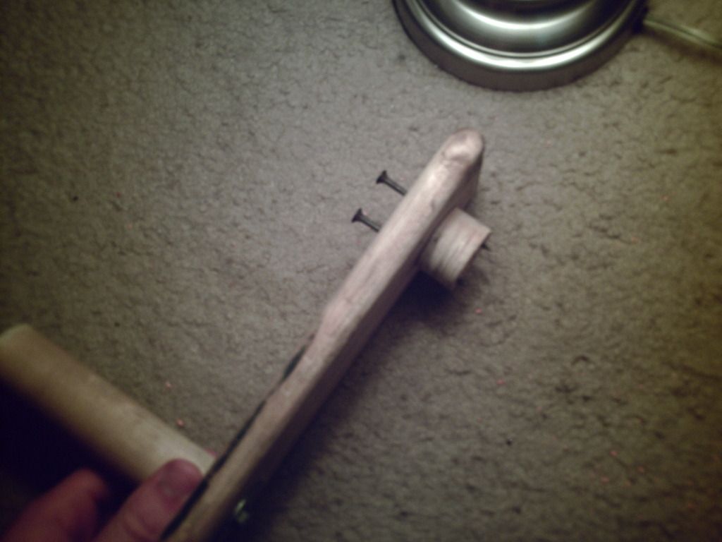
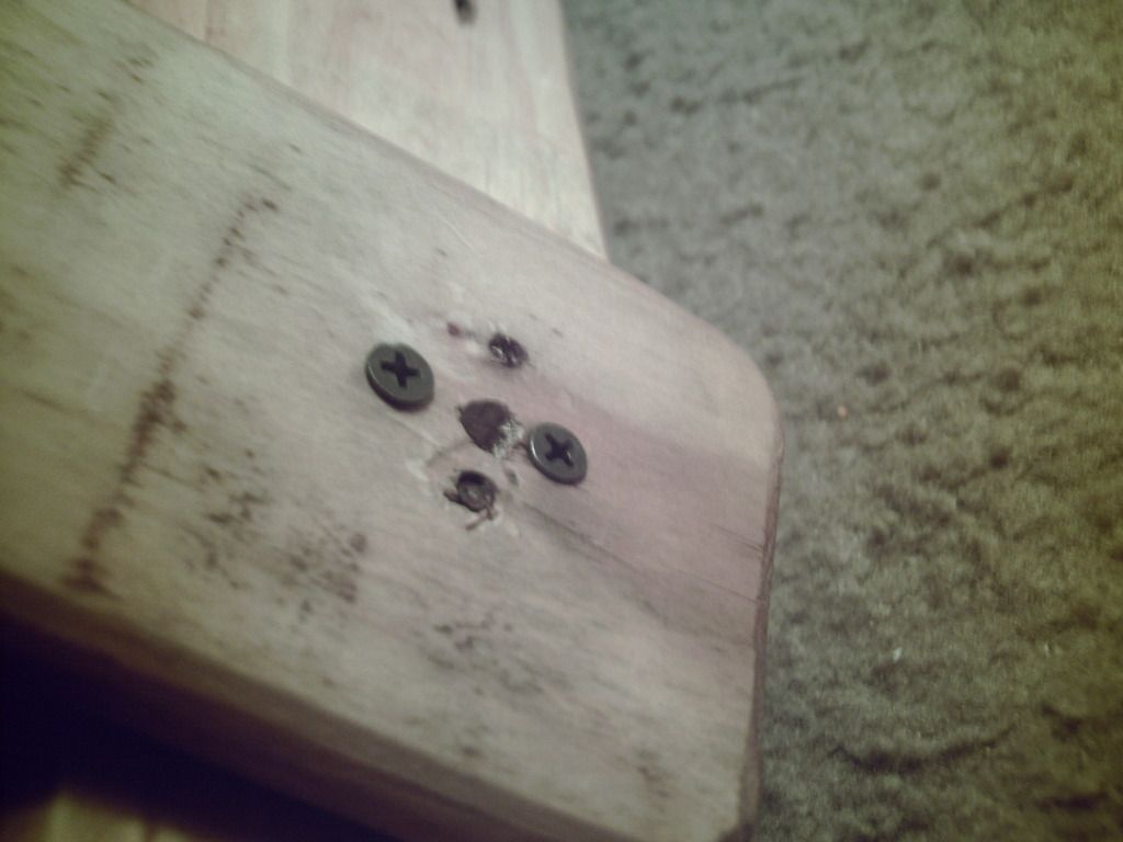
This is the part of the crank that you hold. As you can see, there is an arm with a handle screwed onto it. I used a holesaw to cut the piece that is screwed onto it. The hole in the center of the holesaw core is alligned with a hole in the plank. The screws sticking out will be further screwed when the next peice is aligned.

PHTO0037-1.jpg
Left side of the board, ignore the plank on the right, that is not the handle piece.
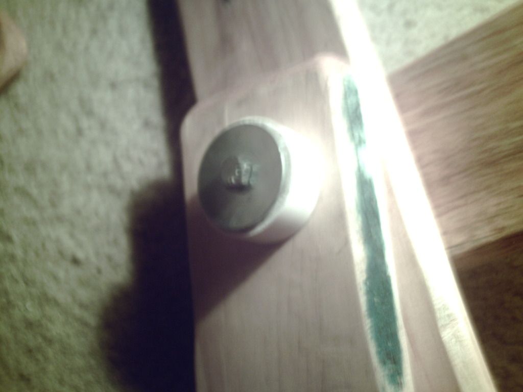
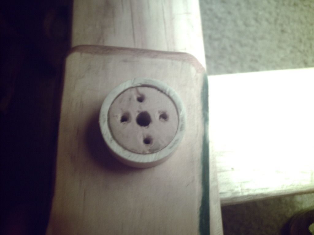
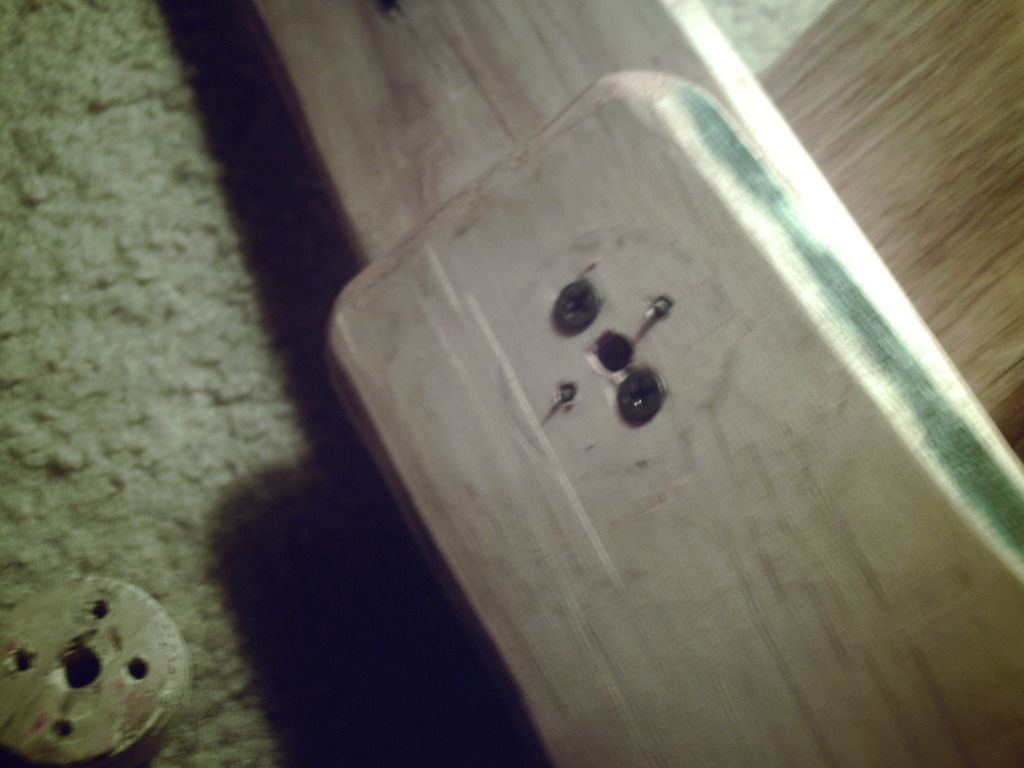
The hole saw core is taken from the plank that is shown here. Thus, making the core requires proper placing, not just maing it anywhere from any plank. File out the hole, and place a 1.25" PVC ring into the hole, it should fit snugly, and mount the previous peice in the right side of the plank, shown below as the right side of the board, and the handle sticking "up" or "to the right".
PHTO0035-1.jpg
PHTO0034-1.jpg
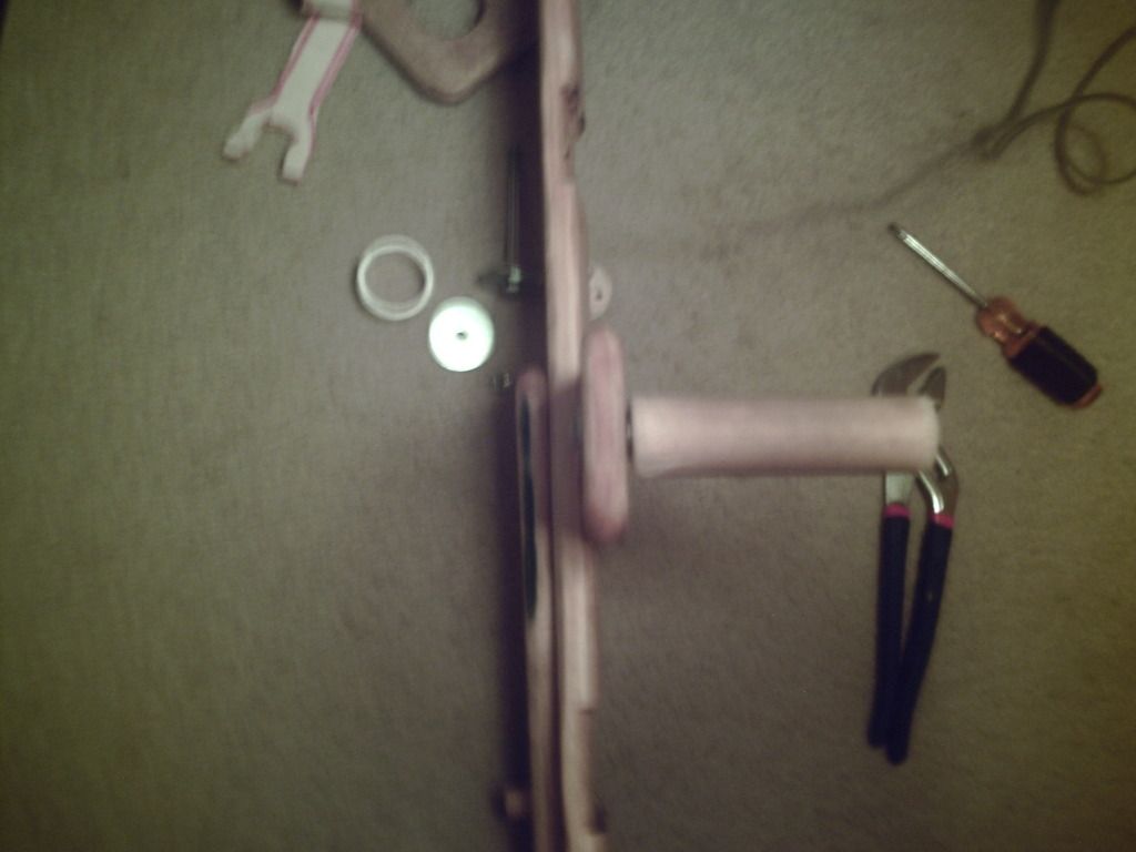
The above picture shows the arm that pushes the priming arm. It is identical to the first arm that was made, except the "handle" on the first has been replaced with a small chunk of a dowel that pushes the arm connected to the plunger rod, which is not shown, but the majority of the arm is shown.
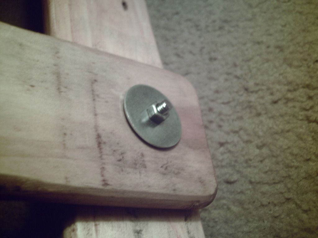
Next is the arm that is connected to the plunger rod. You will use the holesaw to cut a core out of a plank as shown below. The CENTER of the holesaw cut out should be HALF of the DRAW LENGTH of your bow away from the mounting point for the puller. There should be at least another inch of wood beyond the puller post, just for strength. The arm that connects to the plunger rod will mount onto the LEFT side of the blaster, also using the expanded holesaw, 1.24" PVC ring, holesaw core method. ALSO, right under the washer are another two screws going into the crank assembly. They should be able to reach through at least three of the layers of wood, and the first two screws should also do the same, but from the right side. The washer holds the PVC ring onto the assembly, and the ring and the wood arm it connects to should ahve a tight enough fit that they won't fall apart easily.
PHTO0032-1.jpg

The center of the crank mech should be placed so that it is 1.5 times the length of the draw away from the end of the plunger rod's back while at rest. This is done so that the end of the priming arm will be one length of draw away from the end of the plunger at rest. Here is where the sewing takes place.
You will need to stitch a strap out of canvas, the same length as that of the draw of the blaster, that will connect the peg on the priming arm to the back of the plunger rod. Mine ended up being a long Y shape, because there was a bolt near the back of my plunger rod that I was using as a priming handle that was perpendicular to the plane that the bow string rests on. So, the canvas was shaped to hook onto that bolt, straddling the bowstring, and also hooking onto the nylon spacer that was used as the post for the priming arm. I also placed washers at the ends of those bolts to keep them from slipping off of their bolts. This method is a lot cleaner than using a rope, because the rope would slacken, and was bulky. Also, the canvas looked a lot cleaner, even though my stitching looks really janky.

Everything ended up being perfectly alligned the way I made my frame, because the front handle is jsut to the right of the blaster mounting plank, and the plank that mounts the crank mech was just to the right of that. NOT TO SCALE. From the top.~~~~~= empty space.
~~~~~~~~~~~~~~~~~~~~~~~~~~~~~~~~~~~~~~~~~~~~~~~~~~~~Crank handle
~~~~~~~~~~~~~~~~~~~~~~~~----------------------------------------------Crank------------Stock that goes on my hip
~~~~~~~~~~~~~~~~~~~~~~~~~Handle plank~~~~~~~~~~~~~~~Pushing arm
Blaster mounting plank------------------------------~~~~~~~~~~~~~Priming arm
Blaster-------------------------Posts on blaster~~~~~~~~~~~~~~Post on priming arm

That's all I can think of right now. If you would like pictures of something specific, or instructions or descriptions of something I glanced over, just say so.


Edited by Exo, 12 February 2020 - 10:02 PM.

  • 0

#2 evilbunnyo

evilbunnyo

    Member

  • Members
  • 404 posts

Posted 29 August 2012 - 06:50 PM

Oh holy hell. This is kinda over kill scary. I like it. I must ask for the firing video and the best rof youve got from it. Also how heavy is this thing?
  • 0
Silence is golden but duct tape is silver

#3 Exo

Exo

    Member

  • Members
  • 391 posts

Posted 29 August 2012 - 07:02 PM

Oh holy hell. This is kinda over kill scary. I like it. I must ask for the firing video and the best rof youve got from it. Also how heavy is this thing?

http://youtu.be/4SPB0H55B9k
Why can't I embed this?
Um, the frame I made (all the stuff that's not the blaster and bowarms) weighs 5.4lbs, but when you hold it yout in front of you like in the pics, it gets kinda heavy. The bow that I use with it is only 1.1lbs, because it's that dollar store watergun, which has no weight to it anyways.\

Version 2.0's frame will probably be lighter, but the blaster will be heavier, because it will be PVC and use springs.

Edited by Exo, 29 August 2012 - 07:51 PM.

  • 0

#4 Craftsman

Craftsman

    Member

  • Members
  • 96 posts

Posted 29 August 2012 - 07:32 PM

Awesome job, I may need to replicate this just because I can. Would this be easy to mount on to a tripod? That might make it a bit easier to use although it would be even less portable...

Also, "One of those things that you slide along the surface of wood and it strips off curliques to reveal untreated wood underneath," is called a wood plane if I'm not mistaken.
  • 0

Man keep finger on trigger receive painful finger bang!

Olde School Tacticool

All hail #YOLOStock!


I have taken a "break" from the hobby, but if you have anything crazy hit me up. I'm always interested in a challenge. Currently designing a nerf vehicle among other things.


#5 Exo

Exo

    Member

  • Members
  • 391 posts

Posted 29 August 2012 - 07:42 PM

Awesome job, I may need to replicate this just because I can. Would this be easy to mount on to a tripod? That might make it a bit easier to use although it would be even less portable...

Also, "One of those things that you slide along the surface of wood and it strips off curliques to reveal untreated wood underneath," is called a wood plane if I'm not mistaken.

Wood plane? I'll remember that. If you could come up with a reliable mount and legs, probably. You could remove the "hipstock" to minimize it up a bit if you want to do that, without a "hipstock, it's impossible to use without a mount, because you're only connected solidly to it at one point, the other point is the crank and isn't really a stable connection point. I would like to point out at this point that the entire length of it is based off of the draw of the original blaster. If you have a shorter draw, you have a shorter required size.
  • 0

#6 Craftsman

Craftsman

    Member

  • Members
  • 96 posts

Posted 29 August 2012 - 07:45 PM

I'll keep that in mind for when I design mine. Do you have a video of this firing, I would be very interested in watching it, to get an idea of exactly how it all works. Thank you.
  • 0

Man keep finger on trigger receive painful finger bang!

Olde School Tacticool

All hail #YOLOStock!


I have taken a "break" from the hobby, but if you have anything crazy hit me up. I'm always interested in a challenge. Currently designing a nerf vehicle among other things.


#7 Exo

Exo

    Member

  • Members
  • 391 posts

Posted 29 August 2012 - 07:49 PM

I'll keep that in mind for when I design mine. Do you have a video of this firing, I would be very interested in watching it, to get an idea of exactly how it all works. Thank you.

See my second post for the video. It'll be up in a few minutes. Basically, you turn a crank, which is mechanically fastened to another arm on the other side of the frame, and that pushes another arm around, and when the mechanism is halfway through the cycle, the second arm releases the third arm, which is attatched to the plunger rod, the third arm swings forwary, you cycle the crank to catch up the arm assembly, and it all starts over.
  • 0

#8 HasreadCoC

HasreadCoC

    Member

  • Members
  • 274 posts

Posted 29 August 2012 - 08:07 PM

I love this. I love this so much. I've said for a while that we need to go "sideways" in the community, and this is so exactly the sort of thing i had in mind.
  • 0

I'm the only respectable person here. The rest of the NIC are pretty much just child molesters.


AKA: ObiWonTwo on Nerfrevolution, and most of the rest of the internet for that matter.....

#9 CaliforniaPants

CaliforniaPants

    Futtbrustrated

  • Moderators
  • 459 posts

Posted 29 August 2012 - 08:09 PM

The biggest problem I can see is that when you crank it fast you shop the plunger from making its full stroke. If you watch while you fire you're grabbing hold of it about half way to 3/4 through the cycle.
  • 0

trans as shit because fuck you


#10 Exo

Exo

    Member

  • Members
  • 391 posts

Posted 29 August 2012 - 08:39 PM

The biggest problem I can see is that when you crank it fast you shop the plunger from making its full stroke. If you watch while you fire you're grabbing hold of it about half way to 3/4 through the cycle.

I'm a little confused by what you are saying. The way this was designed is that the crank WILL pull the plunger rod all the way back. The only way it won't is if you are using a blaster with a longer draw than the crank was inteded for. If you mean that the handle is catching up to the plunger rod on the way back, then the canvas will get slack, and then that pulls weight off of the bow arms, if that ever happens.
  • 0

#11 Bchamp22795

Bchamp22795

    Member

  • Members
  • 209 posts

Posted 29 August 2012 - 08:58 PM

I'm a little confused by what you are saying. The way this was designed is that the crank WILL pull the plunger rod all the way back. The only way it won't is if you are using a blaster with a longer draw than the crank was inteded for. If you mean that the handle is catching up to the plunger rod on the way back, then the canvas will get slack, and then that pulls weight off of the bow arms, if that ever happens.


He means that the "catch" (or rod that is attached to the crank that pushes the rotating arm) is moving too fast. Before the rotating arm (attached the the plunger rod) gets all the way back to rest position, the catch/crank has already stopped it and is starting on the next rotation. You don't get full draw, and you gain deadspace.
  • 0

#12 Exo

Exo

    Member

  • Members
  • 391 posts

Posted 29 August 2012 - 10:35 PM

Oh, I see what you are saying now. I see how that could happen, but that would probably get worked out with stronger bow arms/springs and a lighter priming arm. V2 may use some aluminium u-channel for the priming arm. A shorter plunger length could also help clean that up.
  • 0

#13 Goldie

Goldie

    Member

  • Members
  • 62 posts

Posted 29 August 2012 - 11:01 PM

The best shits-and-giggles blaster EVER.
  • 0

Longshots are terribad and you should feel bad.
Crossbow shells suck and your mom sucks.


S.C.U.N.

#14 JPRoth1980

JPRoth1980

    Member

  • Members
  • 56 posts

Posted 30 August 2012 - 06:05 AM

So, this is basically an Aabow with 5 pounds of wood attached, right?

Assuming that you are using a nominal draw of 7 inches (just for purposes of demonstration and because of my familiarity with Snaps and the like) your cyclic motion for each crank will be nearly 22 inches compared to the 14 inch motion of firing the Aabow in the first place. You may have a small advantage in that the action is almost never in direct opposition to the force of the bow arms, but I'm not sure if the more than 50% extra travel length is worthwhile in this occasion.

I can see some potential here (specifically for high-K-constant blasters), but in its current incarnation, I can't help but think you'd be better off without the wood frame.
  • 0

#15 Exo

Exo

    Member

  • Members
  • 391 posts

Posted 30 August 2012 - 09:32 AM

So, this is basically an Aabow with 5 pounds of wood attached, right?

Assuming that you are using a nominal draw of 7 inches (just for purposes of demonstration and because of my familiarity with Snaps and the like) your cyclic motion for each crank will be nearly 22 inches compared to the 14 inch motion of firing the Aabow in the first place. You may have a small advantage in that the action is almost never in direct opposition to the force of the bow arms, but I'm not sure if the more than 50% extra travel length is worthwhile in this occasion.

I can see some potential here (specifically for high-K-constant blasters), but in its current incarnation, I can't help but think you'd be better off without the wood frame.

During the initial fining tests, I did feel that I could fire the bow by itself faster, more accurately, and because of the heigth difference, farther. So if I were going for direct war feasibility, I wouldn't have made this at all.

Edited by Exo, 30 August 2012 - 09:32 AM.

  • 0

#16 durka durka

durka durka

    Member

  • Members
  • 364 posts

Posted 30 August 2012 - 10:19 AM

This is a really neat concept. I imagine a bow with larger plunger volume and hopper capacity could really take advantage of the superior rof.

Have you considered orienteering the bow arms to a crossbow-like appearance? If not just for purely cosmetic purposes, it might be easier to aim without bow arms in the way.
  • 0
"The warrior who cultivates his mind polishes his arms"

#17 Exo

Exo

    Member

  • Members
  • 391 posts

Posted 30 August 2012 - 11:10 AM

This is a really neat concept. I imagine a bow with larger plunger volume and hopper capacity could really take advantage of the superior rof.

Have you considered orienteering the bow arms to a crossbow-like appearance? If not just for purely cosmetic purposes, it might be easier to aim without bow arms in the way.

Well, It would ba a bit more complicated to make it, but it could be done. Of coure, you could also use springs.
  • 0

#18 Plopper

Plopper

    Member

  • Members
  • 27 posts

Posted 30 August 2012 - 07:36 PM

This isnt over kill. Its WAY over overkill....
Its overkill beutifull!
Overkill.
  • 0
The picture says all. I am the wise man.

(\__/)
(+'.'+) This is Bunny. Copy and paste bunny
(")_(") into your profile to help him gain world domination. (yes i found this on another profile)

My Blog
-plopper

#19 Exo

Exo

    Member

  • Members
  • 391 posts

Posted 31 August 2012 - 01:02 AM

Someone mentioned that my explanation doesn't really explain it, but it's kinda one of those things you have to see for yourself, so I'm going to get some better detailed pictures of the mechanism up tomorrow. Hopefully they should clear up any questions you have about how it works.

EDIT: Here's a video
of how the mechanism works, I hope that this will clear up any questions anyone has.
Posted Image
Fully assembled.

Posted Image
Right side hardware.

Posted Image
Left side hardware with the leftmost arm removed from the "axle".

Posted Image
Under the washer, washers and bolt removed.

Posted Image
Right side, under the washer. Loosen these two screws to remove the wood core on the left side, revealing:

Posted Image
Left side, under the wood core.

Posted Image
Three layers of wood. The middle "layer" has a wood core/PVC hub assembly, the "outside" two layers are connected by four screws through the wood core in the middle layer.

Edited by Exo, 01 September 2012 - 09:58 AM.

  • 0


1 user(s) are reading this topic

0 members, 1 guests, 0 anonymous users