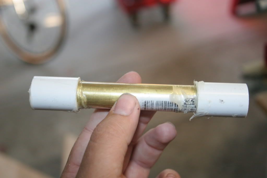
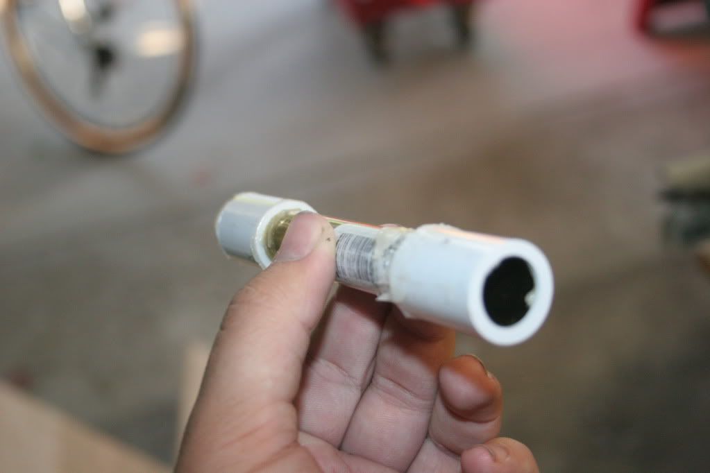
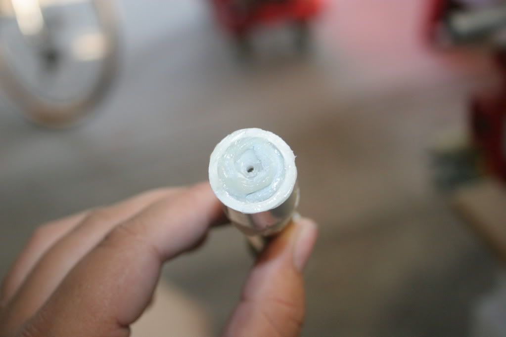
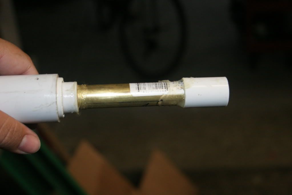
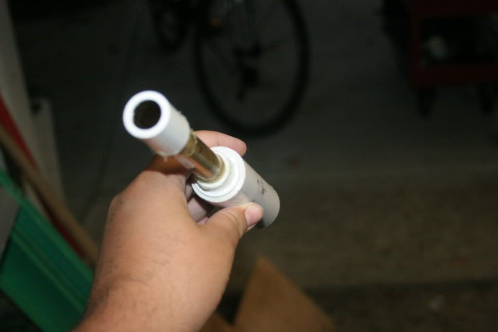
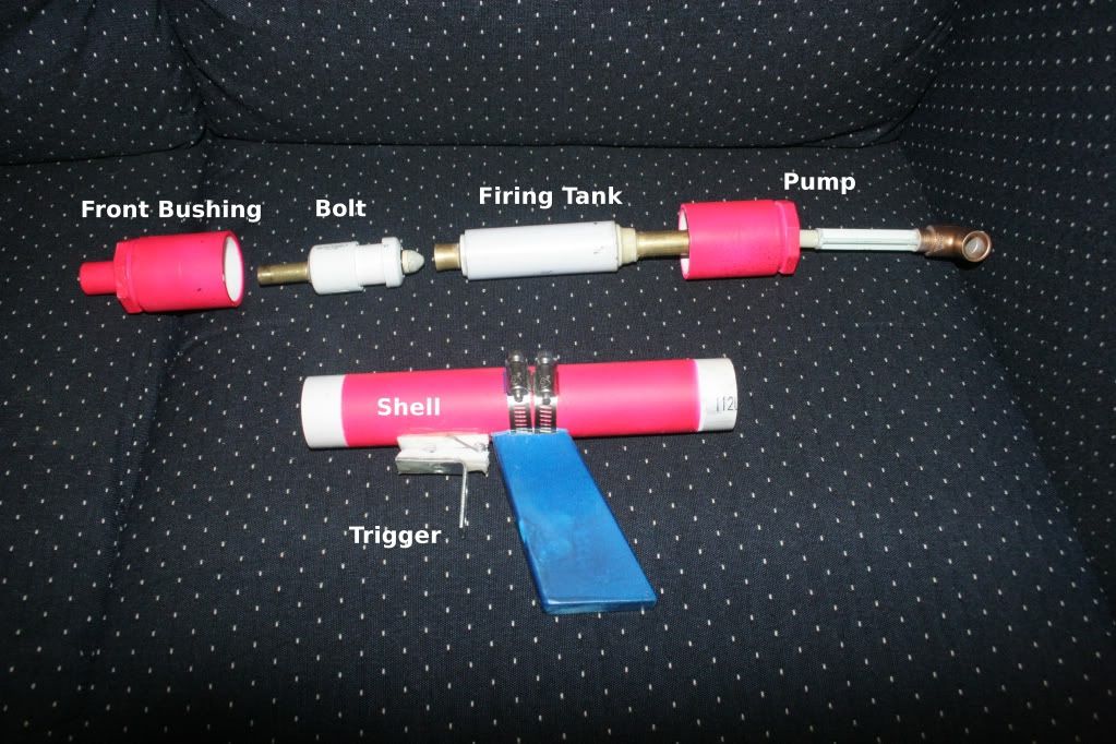
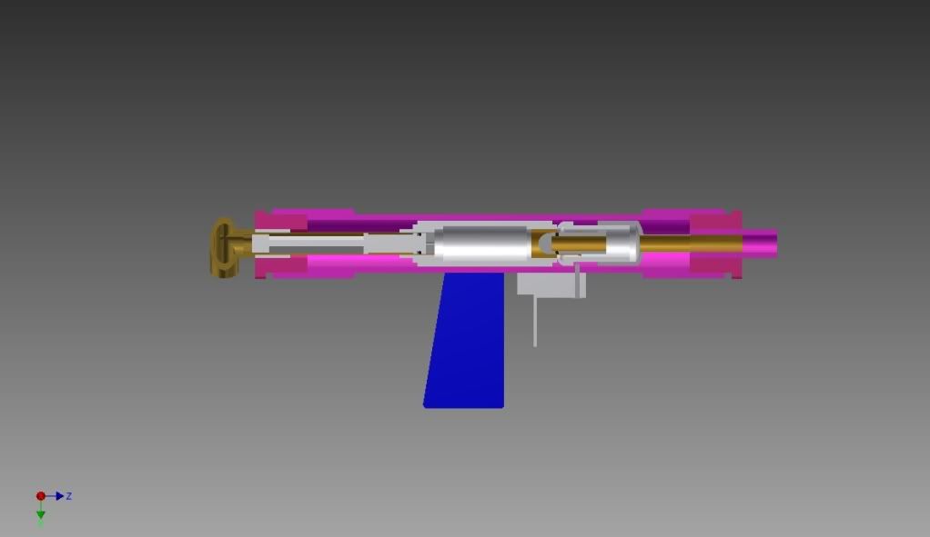
Well, to start it off, here's an intro video, just to give a general idea of what I built.
http://www.youtube.com/watch?v=FUA1BXbD9nA
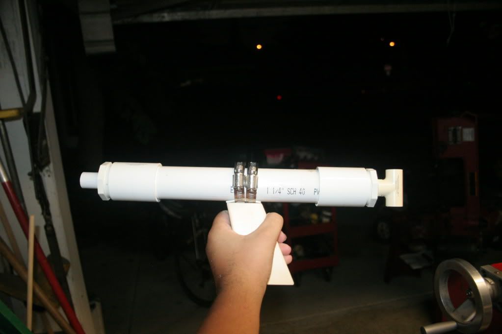
As you can plainly see, this is not your ordinary springer. I present the SCUNBAG - SoCal's Uber-New Bodacious Air Gun.
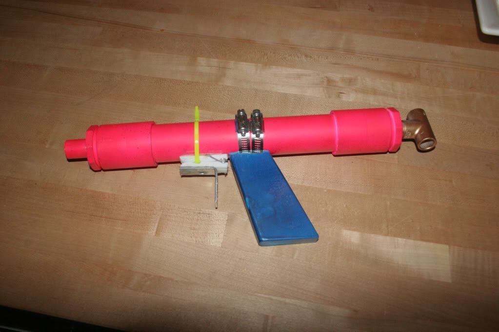
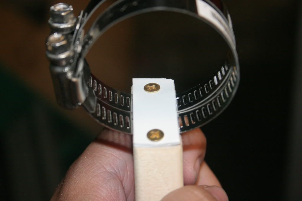
(The zip tie was just to keep the trigger from moving while the epoxy dried)
-------------------------------------------------------------
(Skip this part if you just want to build the blaster)
First, a little background on the design. I discovered NerfHaven about a year before Carbon posted his first SNAP. Unfortunately, I was 10-ish at the time, and didn't want to lie about my age, fearing the wrath of Vacc. My first homemade, and second gun in my arsenal was a SNAP-1 MK II. It lasted quite a while, and I had plenty of fun with it. Eventually, I moved on to bigger and "better" things, and got my first AT2K a couple of years later. I fell in love with airguns through this, and was dismayed to discover that most, if not all wars ban homemade airguns. That same year, I went to my first war - Armageddon X. After that day in Glendora, I was permanently hooked on Nerfing.
Fast-forward three years to the start of the Homemades Contest. VACC's "side bet" for airguns intrigued me, and I started coming up with designs, many of which were quite complicated, and could only be completed with the help of large, expensive tools (which, of course, I have access to). This was simply no good - a design doesn't benefit the community, unless others can build it and learn from it. For a couple months, I forgot about the contest, and remembered about it right before the initial deadline. I was scrambling to come up with something, until I saw that Ryan had extended the deadline. This gave me time to come up with a really robust, simple to build system.
Since a SNAP was the first homemade for me, along with many other members, I figured I might as well go "back to basics" with a simple homemade airgun for the contest, that could easily be expanded (like the original SNAP).
At first, I was experimenting with backpressure tanks, which turned out to be finicky on a small-scale. Stuck with absolutely nothing and a week left in the contest, I turned to ZDSPB for some inspiration. The "Automag" design (see below) caught my eye, since it looked relatively simple to build, and could easily fit into a SNAP form-factor. I designed and built a functioning prototype in a day. </lots of text>
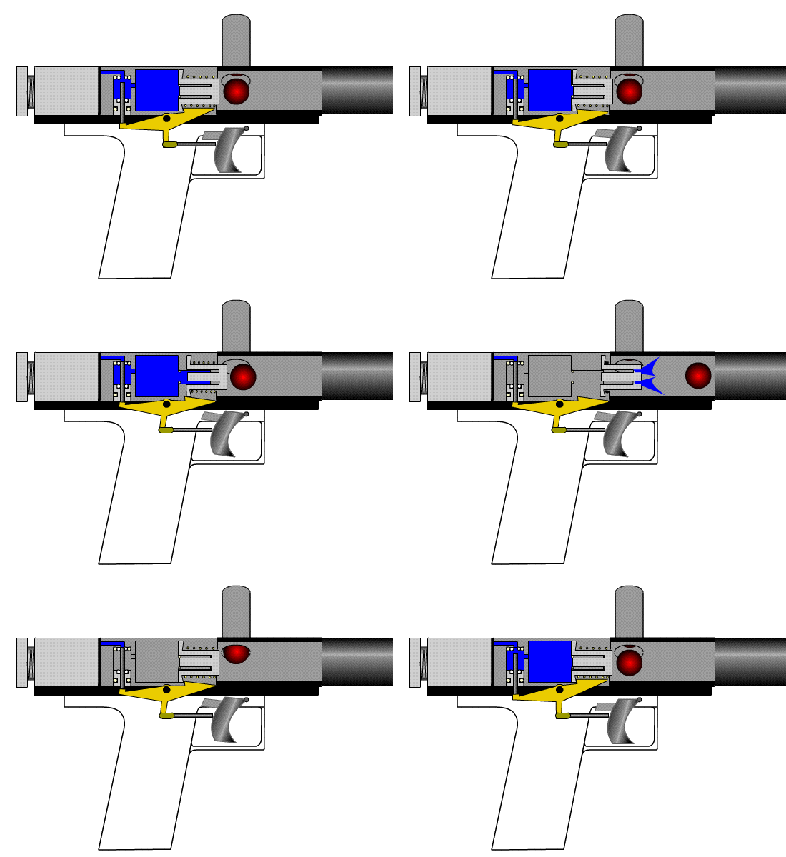
"Automag" design
(Stop skipping here, if you didn't read the above paragraphs)
------------------------------------------------------------
Materials list:
Pipe (You won't need nearly this much)
1'- 1 1/4" Sch. 40 PVC
1'- 1" Sch. 40 PVC
1'- 3/4" Sch. 40 PVC
1'- 1/2" CPVC
Fittings
2x - 1 1/4" Slip x Slip female coupler
2x - 1 1/4" x 1/2" Slip bushing
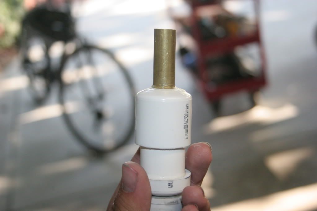
2x - 3/4" x 1/2" Slip bushing (IMPORTANT: See pic below)
2x - 3/4" Endcap
1x - 1/2" CPVC Tee
Other Stuff
1' - 7/16" K&S brass tube
1' - 1/2" K&S brass tube
1' - 17/32" K&S brass tube
1' - 21/32" K&S brass tube
1x - 5/8" x 7/16" O-ring
Check Valve (I used 7757K41)
Pump of some sort (Venom's homemade 2K pump would work well. My attempt at a simple homemade pump failed, so I ended up using a shortened 2K pump.)
Ace #156 spring
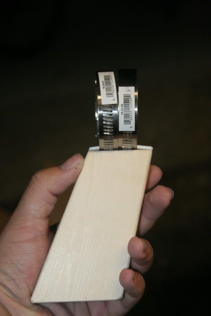
2x - 1 3/4" Hose Clamps (Smaller would probably work, I just happened to have these)
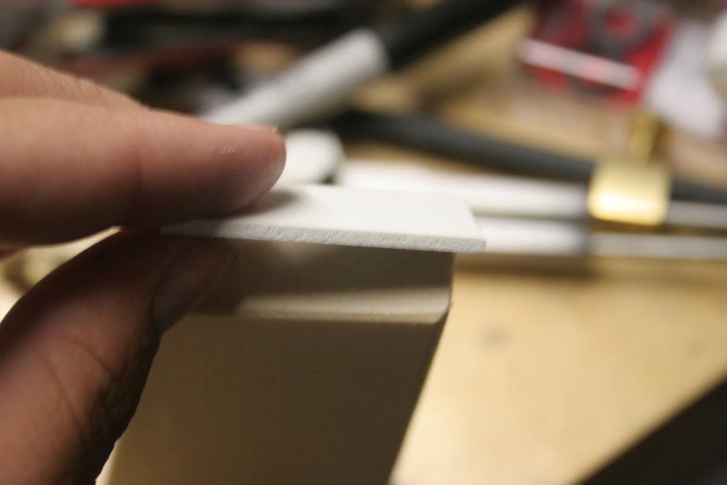
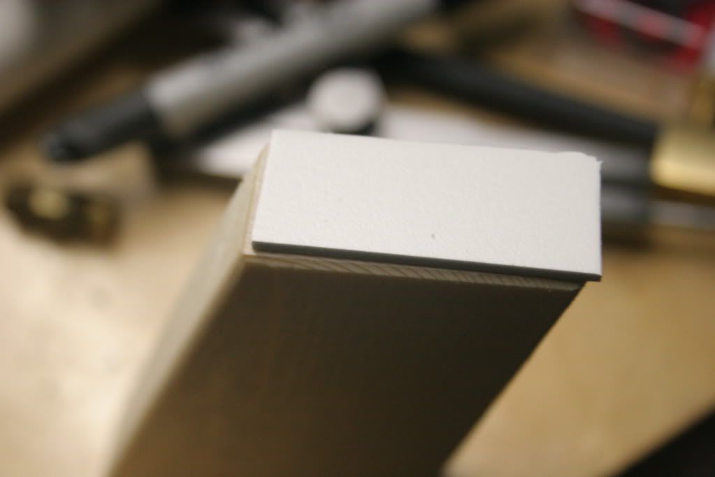
Thin (.050-.080") PVC or Aluminum sheet
#8 x 1/2" wood screws
1"x2"x12" dimensional lumber
Clothespin trigger (See Carbon's SNAP-1 MK II writeup)
Epoxy Putty
E-Tape/Masking Tape
Epoxy
PVC Primer/Cement
Super Glue
(If I forgot anything, let me know)
Required Tools
Dremel
Hacksaw
Pipe cutters
Optional Tools (Really, really handy)
Belt Sander
Miter Saw
Arbor Press
Horizontal Bandsaw
Metal Lathe
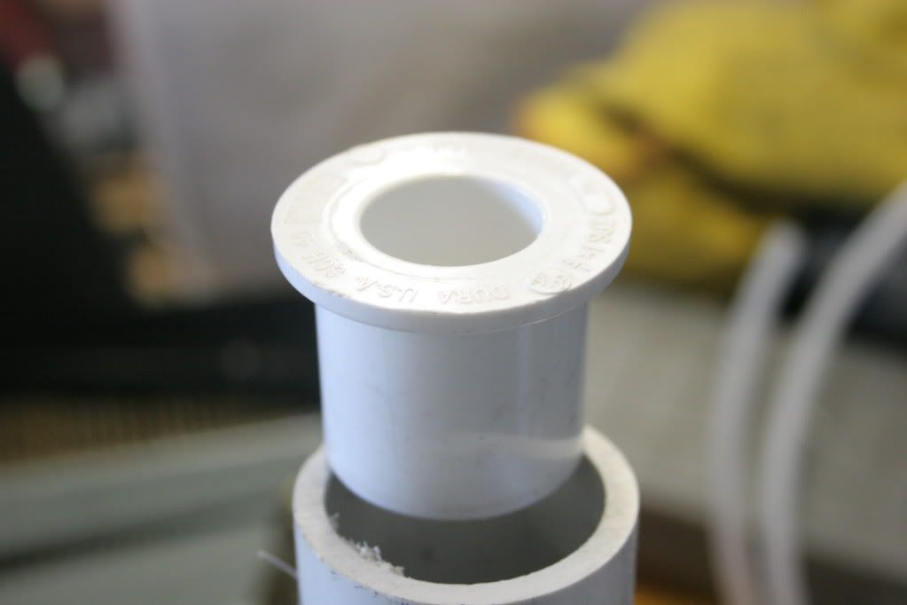
3/4"x1/2" Bushing (They fit really nicely in 1" Sch. 40 PVC)
Let's start building!
Step 1:
Cut a piece of 1" PVC 3 7/8" long. This will become the main tank. With the bushings installed, the volume is similar to that of a 2K tank.
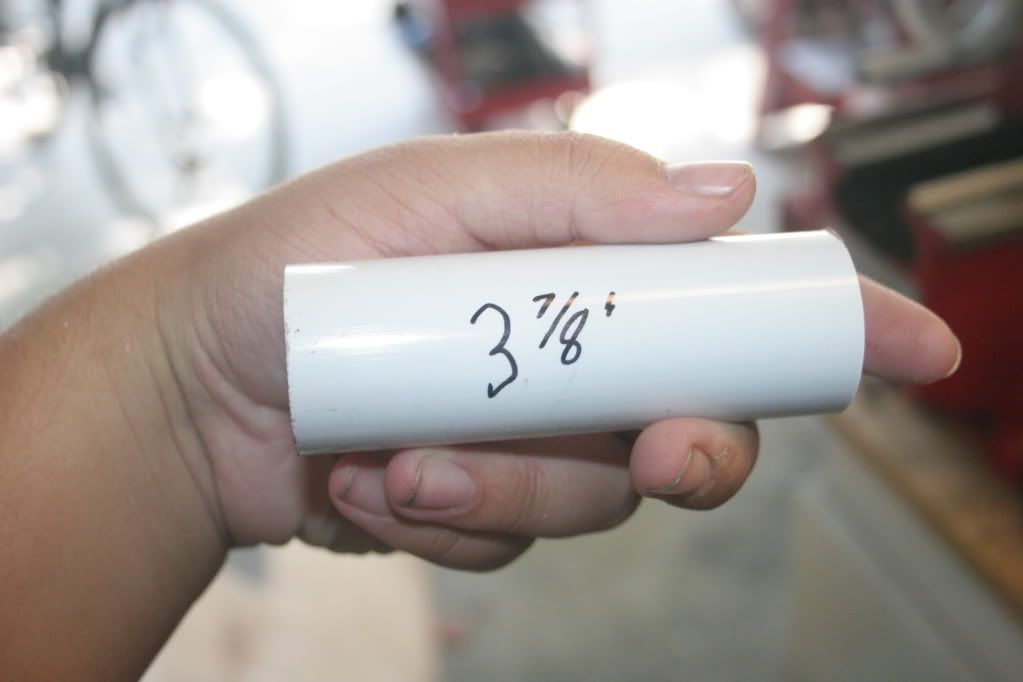
Step 2:
Install a 3/4" x 1/2" bushing in one end. Depending on your pipe, this could be quite difficult to do, and may require some creative dremeling to get it to fit nicely. Solvent weld it in. This will become the firing tank.
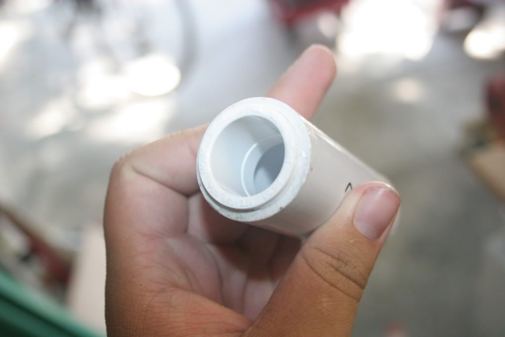
Step 3:
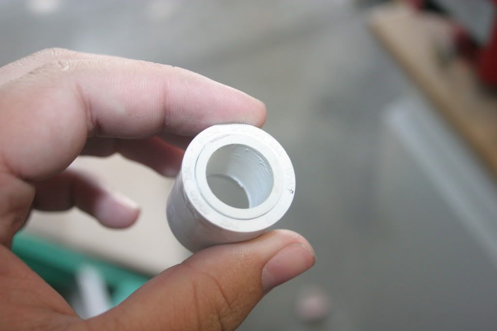
Cut a .75" long piece of 1/2" PVC. Solvent weld it into your other 3/4"x1/2" bushing.
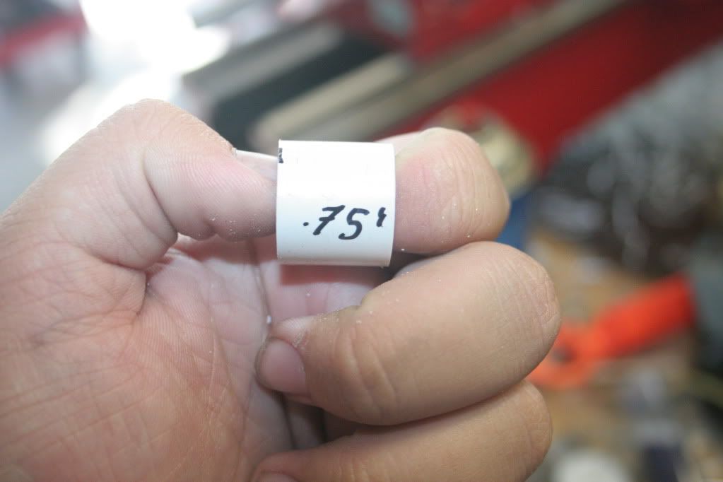
Step 4:
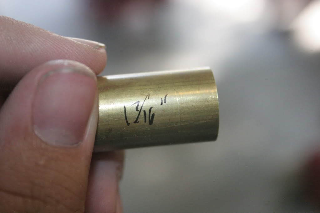
Cut a 1 7/16" long piece of 21/32" brass tubing.
Step 5:
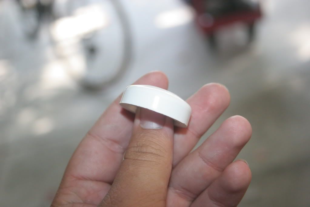
Cut the end off of a 3/4" endcap, leaving about 1/4" of the slip section before the little lip on the inside of the cap, so you can still install it on a piece of PVC.
Step 6:
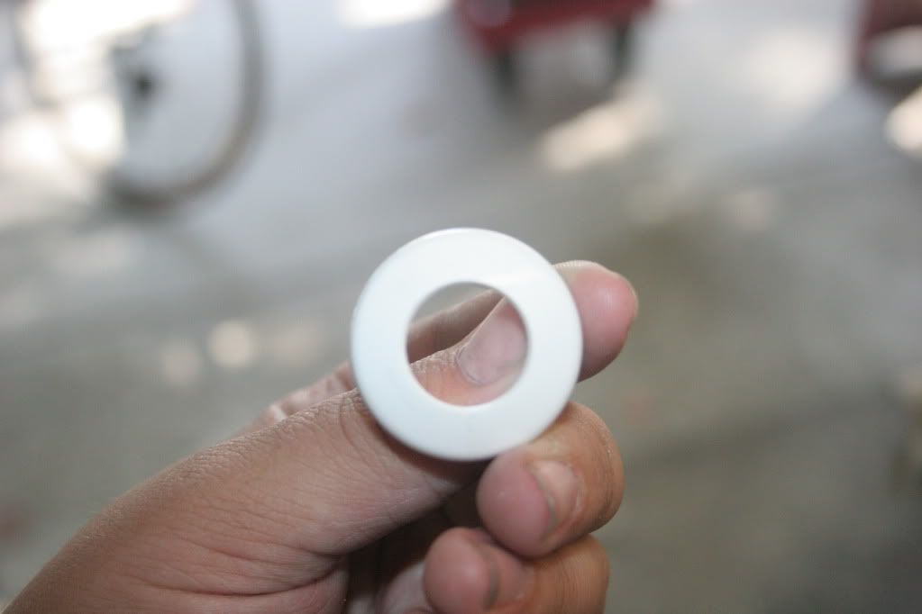
Drill a ~3/4" hole in the center of that endcap slice. The actual dimension is not particularly important, it just has to be around 3/4".
Step 7:
Cut a ~1 5/8" long piece of 7/16" brass tubing, and wrap E-tape or masking tape around it, so that 1/2" CPVC is snug on it.
Step 8:
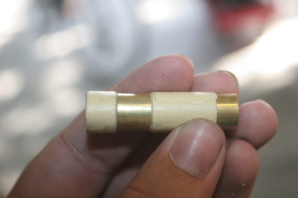
Cut a 1/8" long segment of 1/2" CPVC and press it onto the end of the brass tube, leaving about 1/4" between the segment and the end of the tube. Sand the CPVC to slide smoothly inside 21/32" brass tube. Place the 5/8"x7/16" O-ring against the segment.
Step 9:
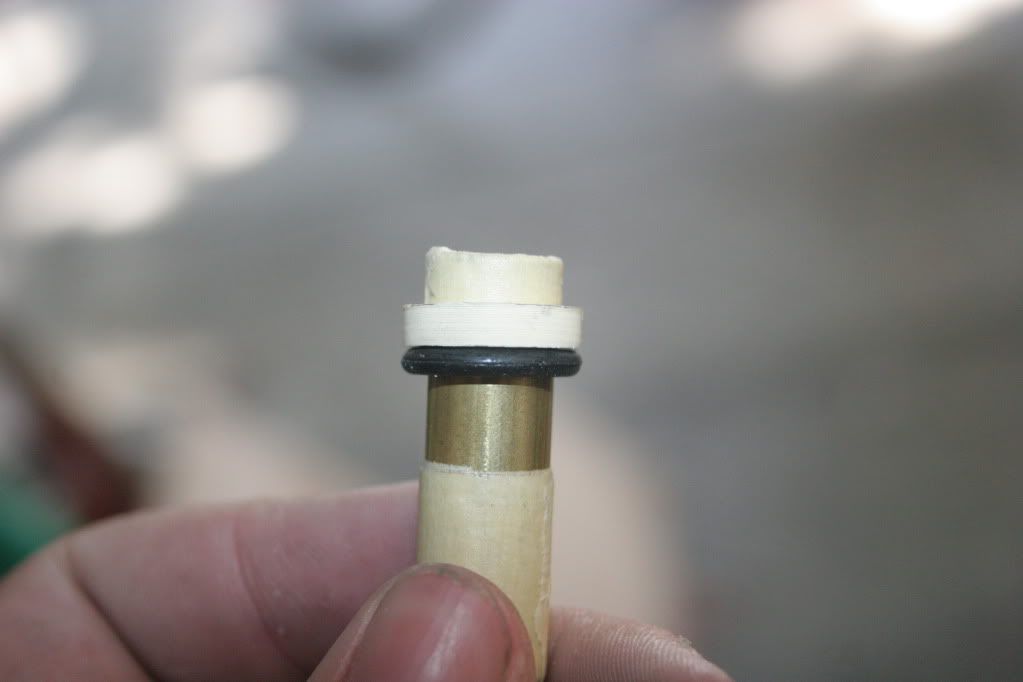
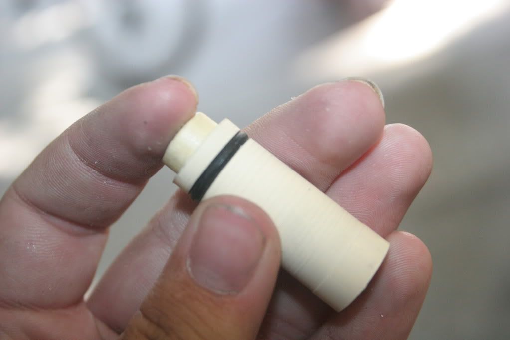
Cut another segment of 1/2" CPVC long enough that it covers the rest of the brass tube, with the O-ring in place. Sand to slide smoothly inside 21/32" brass tube. Slide it onto the tube, and check to make sure that everything lines up correctly before using super glue to secure both segments. Make sure not to get glue on the O-ring.
Step 10:
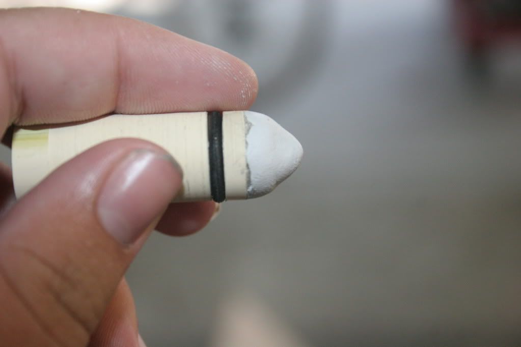
Use epoxy putty to plug the ends of the 7/16" brass, and build up a small cone on the O-ring end of the tube.
Step 11:
After the E-putty dries, cut a section of 1/2" PVC and sand the inside to fit snugly over the end of the 1/2" CPVC. Super glue it on, and cut out three sections of it with a dremel, like so:
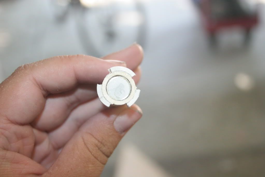
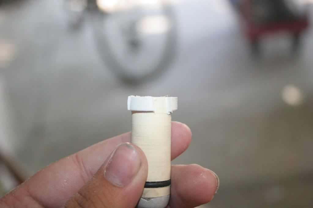
The completed assembly is called the piston.
Step 12:
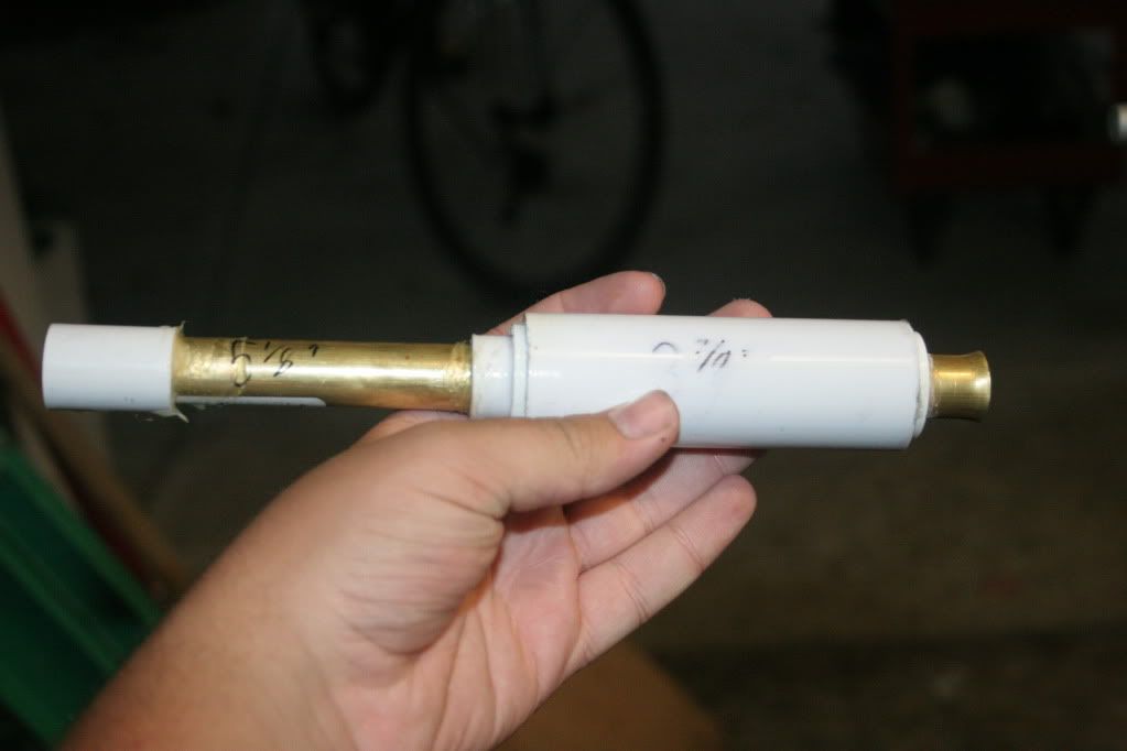
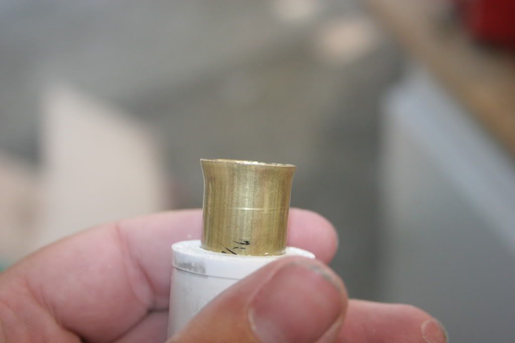
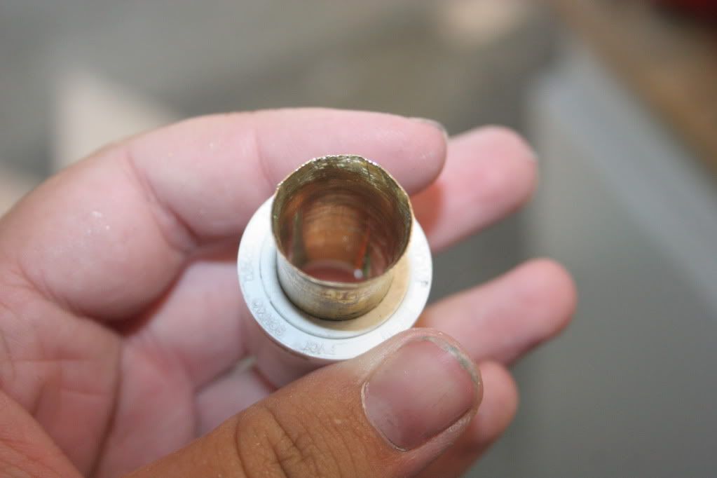
Insert the piece of 21/32" brass from step 4 into the bushing/PVC combo from step 3, sanding out the 1/2" PVC as needed. Use epoxy to secure it. Flare the end of the tubing to the point that it fits in the hole in the 3/4" endcap from earlier, but allows some slop, to account for any mistakes made later on. This assembly is called the front tank bushing.
Step 13:
Cut a segment of 3/4" PVC 1 5/8" long, and install the endcap from step 5. Glue the piston in this assembly, so the O-ring is approximately flush with the end of the endcap. The completed assembly is called the bolt.
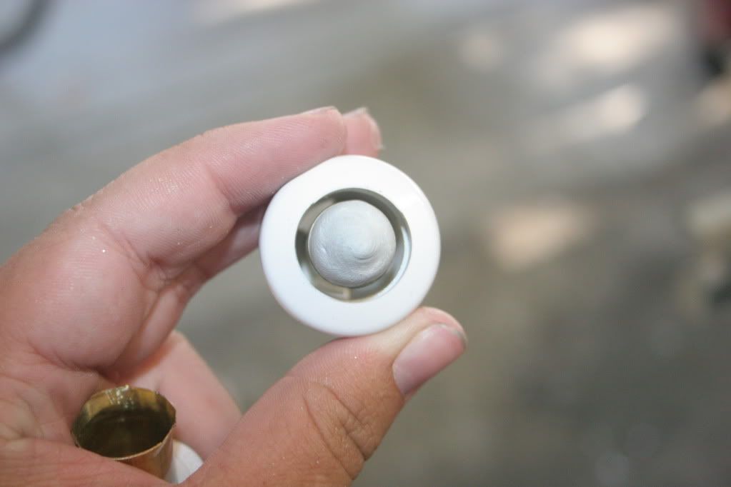
Step 14:
Cut a piece of 17/32" brass tubing and a piece of 1/2" tubing 1.5" long.
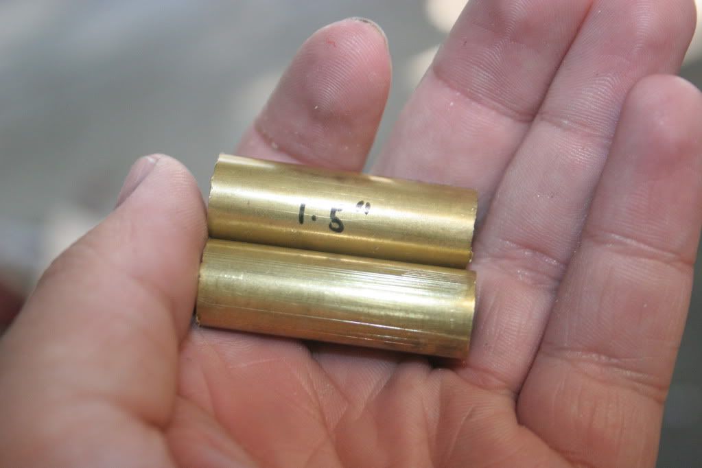
Step 15:
Drill a 1/2" hole in the end of the other 3/4" endcap, and glue the piece of 1/2" tubing inside, so that the end is flush with the inside of the cap. Press this assembly onto the assembly from step 13, but do not glue it, in case you need to make adjustments later.
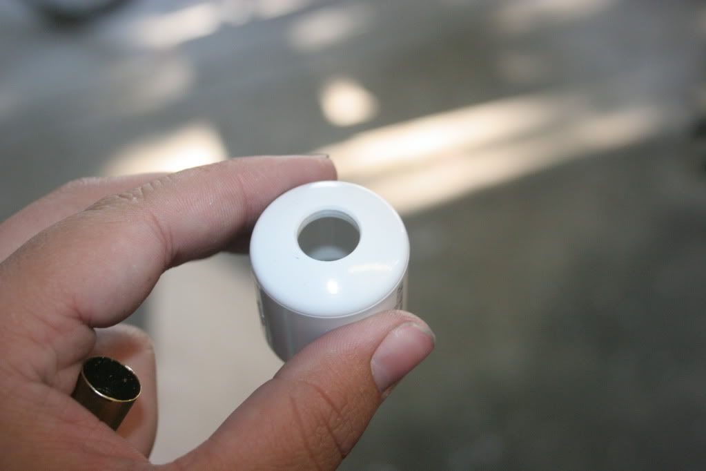
Step 15:
Wrap the piece of 17/32" brass tubing in e-tape or masking tape, so that it is snug inside of 1/2" PVC.
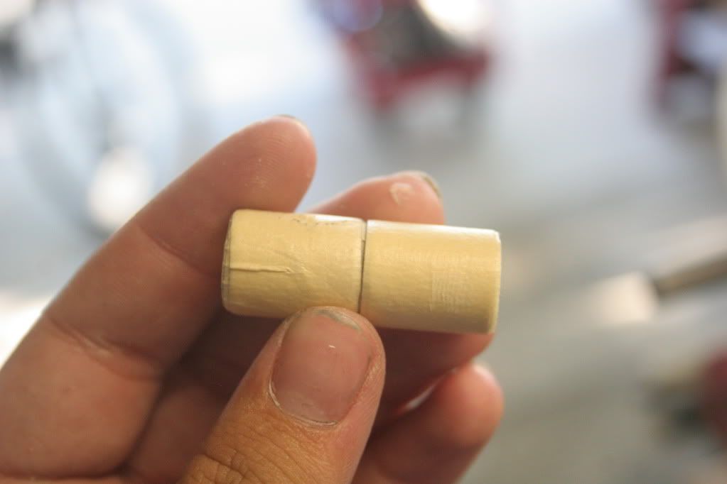
Step 17:
Cut a segment of 1/2" PVC long enough that it can sit flush with the back end of a 1 1/4" PVC bushing and protrude about 3/4" from the front. Solvent weld it into a 1 1/4" bushing, after dremeling out the bushing so that the PVC can slide all the way through. Insert the 17/32" brass tube into the 1/2" PVC, making sure that it is flush with the end.
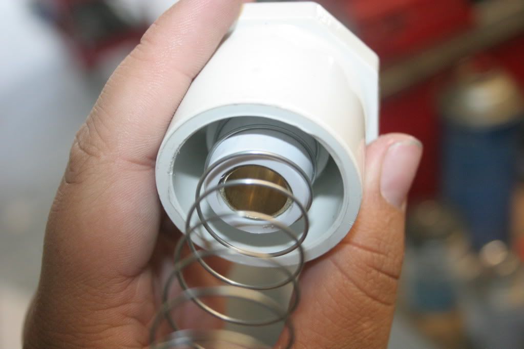
(Ignore the spring, evidently I didn't take a picture without it.)
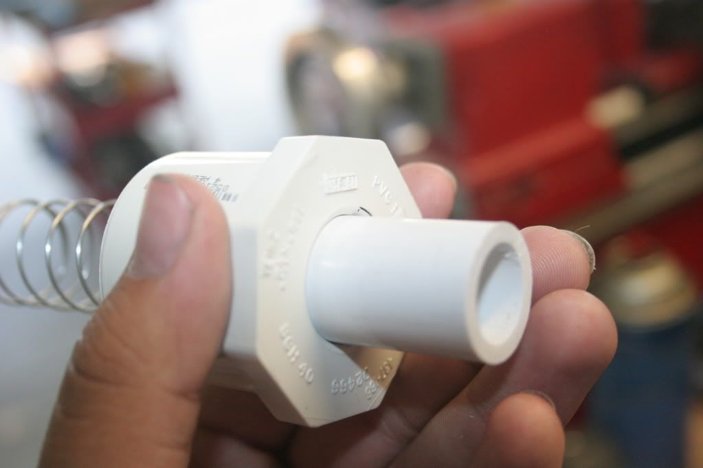
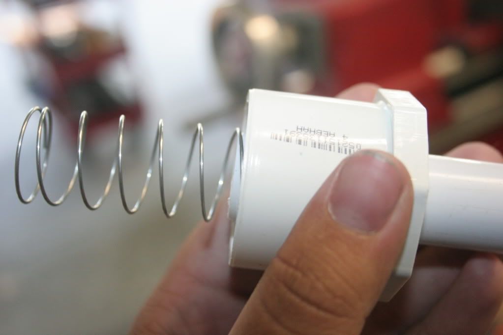
Step 18:
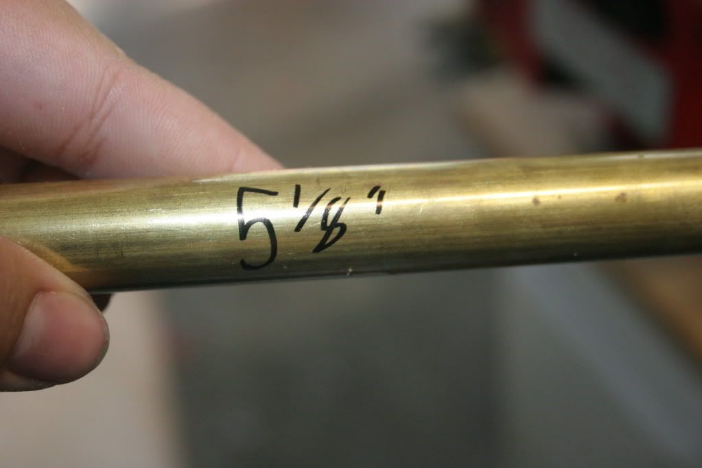
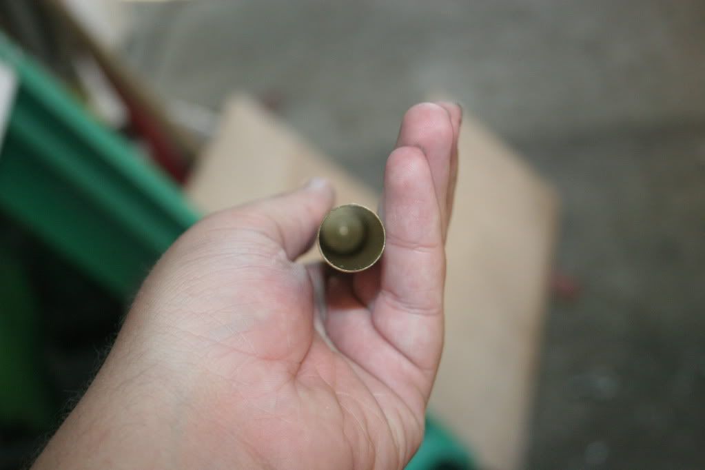
Cut a section of 21/32" brass tubing 5 1/8" long. This will become the pump tube.
Step 19:
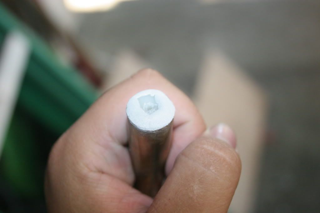
E-putty a check valve into one end of the tubing. Cut both hose barbs off, and make sure the arrow is pointing towards the end of the tube.
End of post #1 (picture limit)
Edited by roboman, 16 March 2013 - 03:36 PM.


